EP1170024B1 - Vorrichtung zur Injektion eines Medikamentes - Google Patents
Vorrichtung zur Injektion eines Medikamentes Download PDFInfo
- Publication number
- EP1170024B1 EP1170024B1 EP01102303A EP01102303A EP1170024B1 EP 1170024 B1 EP1170024 B1 EP 1170024B1 EP 01102303 A EP01102303 A EP 01102303A EP 01102303 A EP01102303 A EP 01102303A EP 1170024 B1 EP1170024 B1 EP 1170024B1
- Authority
- EP
- European Patent Office
- Prior art keywords
- injection
- injection cannula
- micropump
- medicament
- contact
- Prior art date
- Legal status (The legal status is an assumption and is not a legal conclusion. Google has not performed a legal analysis and makes no representation as to the accuracy of the status listed.)
- Expired - Lifetime
Links
Images


Classifications
-
- A—HUMAN NECESSITIES
- A61—MEDICAL OR VETERINARY SCIENCE; HYGIENE
- A61M—DEVICES FOR INTRODUCING MEDIA INTO, OR ONTO, THE BODY; DEVICES FOR TRANSDUCING BODY MEDIA OR FOR TAKING MEDIA FROM THE BODY; DEVICES FOR PRODUCING OR ENDING SLEEP OR STUPOR
- A61M5/00—Devices for bringing media into the body in a subcutaneous, intra-vascular or intramuscular way; Accessories therefor, e.g. filling or cleaning devices, arm-rests
- A61M5/14—Infusion devices, e.g. infusing by gravity; Blood infusion; Accessories therefor
- A61M5/168—Means for controlling media flow to the body or for metering media to the body, e.g. drip meters, counters ; Monitoring media flow to the body
- A61M5/172—Means for controlling media flow to the body or for metering media to the body, e.g. drip meters, counters ; Monitoring media flow to the body electrical or electronic
- A61M5/1723—Means for controlling media flow to the body or for metering media to the body, e.g. drip meters, counters ; Monitoring media flow to the body electrical or electronic using feedback of body parameters, e.g. blood-sugar, pressure
-
- A—HUMAN NECESSITIES
- A61—MEDICAL OR VETERINARY SCIENCE; HYGIENE
- A61M—DEVICES FOR INTRODUCING MEDIA INTO, OR ONTO, THE BODY; DEVICES FOR TRANSDUCING BODY MEDIA OR FOR TAKING MEDIA FROM THE BODY; DEVICES FOR PRODUCING OR ENDING SLEEP OR STUPOR
- A61M5/00—Devices for bringing media into the body in a subcutaneous, intra-vascular or intramuscular way; Accessories therefor, e.g. filling or cleaning devices, arm-rests
- A61M5/14—Infusion devices, e.g. infusing by gravity; Blood infusion; Accessories therefor
- A61M5/142—Pressure infusion, e.g. using pumps
- A61M5/14212—Pumping with an aspiration and an expulsion action
- A61M5/14224—Diaphragm type
-
- A—HUMAN NECESSITIES
- A61—MEDICAL OR VETERINARY SCIENCE; HYGIENE
- A61M—DEVICES FOR INTRODUCING MEDIA INTO, OR ONTO, THE BODY; DEVICES FOR TRANSDUCING BODY MEDIA OR FOR TAKING MEDIA FROM THE BODY; DEVICES FOR PRODUCING OR ENDING SLEEP OR STUPOR
- A61M5/00—Devices for bringing media into the body in a subcutaneous, intra-vascular or intramuscular way; Accessories therefor, e.g. filling or cleaning devices, arm-rests
- A61M5/14—Infusion devices, e.g. infusing by gravity; Blood infusion; Accessories therefor
- A61M5/142—Pressure infusion, e.g. using pumps
- A61M5/14244—Pressure infusion, e.g. using pumps adapted to be carried by the patient, e.g. portable on the body
- A61M5/14248—Pressure infusion, e.g. using pumps adapted to be carried by the patient, e.g. portable on the body of the skin patch type
-
- A—HUMAN NECESSITIES
- A61—MEDICAL OR VETERINARY SCIENCE; HYGIENE
- A61M—DEVICES FOR INTRODUCING MEDIA INTO, OR ONTO, THE BODY; DEVICES FOR TRANSDUCING BODY MEDIA OR FOR TAKING MEDIA FROM THE BODY; DEVICES FOR PRODUCING OR ENDING SLEEP OR STUPOR
- A61M5/00—Devices for bringing media into the body in a subcutaneous, intra-vascular or intramuscular way; Accessories therefor, e.g. filling or cleaning devices, arm-rests
- A61M5/14—Infusion devices, e.g. infusing by gravity; Blood infusion; Accessories therefor
- A61M5/168—Means for controlling media flow to the body or for metering media to the body, e.g. drip meters, counters ; Monitoring media flow to the body
- A61M5/16877—Adjusting flow; Devices for setting a flow rate
-
- A—HUMAN NECESSITIES
- A61—MEDICAL OR VETERINARY SCIENCE; HYGIENE
- A61M—DEVICES FOR INTRODUCING MEDIA INTO, OR ONTO, THE BODY; DEVICES FOR TRANSDUCING BODY MEDIA OR FOR TAKING MEDIA FROM THE BODY; DEVICES FOR PRODUCING OR ENDING SLEEP OR STUPOR
- A61M5/00—Devices for bringing media into the body in a subcutaneous, intra-vascular or intramuscular way; Accessories therefor, e.g. filling or cleaning devices, arm-rests
- A61M5/14—Infusion devices, e.g. infusing by gravity; Blood infusion; Accessories therefor
- A61M5/168—Means for controlling media flow to the body or for metering media to the body, e.g. drip meters, counters ; Monitoring media flow to the body
- A61M5/172—Means for controlling media flow to the body or for metering media to the body, e.g. drip meters, counters ; Monitoring media flow to the body electrical or electronic
-
- A—HUMAN NECESSITIES
- A61—MEDICAL OR VETERINARY SCIENCE; HYGIENE
- A61M—DEVICES FOR INTRODUCING MEDIA INTO, OR ONTO, THE BODY; DEVICES FOR TRANSDUCING BODY MEDIA OR FOR TAKING MEDIA FROM THE BODY; DEVICES FOR PRODUCING OR ENDING SLEEP OR STUPOR
- A61M5/00—Devices for bringing media into the body in a subcutaneous, intra-vascular or intramuscular way; Accessories therefor, e.g. filling or cleaning devices, arm-rests
- A61M5/14—Infusion devices, e.g. infusing by gravity; Blood infusion; Accessories therefor
- A61M5/142—Pressure infusion, e.g. using pumps
- A61M5/14244—Pressure infusion, e.g. using pumps adapted to be carried by the patient, e.g. portable on the body
- A61M5/14248—Pressure infusion, e.g. using pumps adapted to be carried by the patient, e.g. portable on the body of the skin patch type
- A61M2005/14252—Pressure infusion, e.g. using pumps adapted to be carried by the patient, e.g. portable on the body of the skin patch type with needle insertion means
- A61M2005/14256—Pressure infusion, e.g. using pumps adapted to be carried by the patient, e.g. portable on the body of the skin patch type with needle insertion means with means for preventing access to the needle after use
-
- A—HUMAN NECESSITIES
- A61—MEDICAL OR VETERINARY SCIENCE; HYGIENE
- A61M—DEVICES FOR INTRODUCING MEDIA INTO, OR ONTO, THE BODY; DEVICES FOR TRANSDUCING BODY MEDIA OR FOR TAKING MEDIA FROM THE BODY; DEVICES FOR PRODUCING OR ENDING SLEEP OR STUPOR
- A61M5/00—Devices for bringing media into the body in a subcutaneous, intra-vascular or intramuscular way; Accessories therefor, e.g. filling or cleaning devices, arm-rests
- A61M5/14—Infusion devices, e.g. infusing by gravity; Blood infusion; Accessories therefor
- A61M5/142—Pressure infusion, e.g. using pumps
- A61M5/14244—Pressure infusion, e.g. using pumps adapted to be carried by the patient, e.g. portable on the body
- A61M2005/14268—Pressure infusion, e.g. using pumps adapted to be carried by the patient, e.g. portable on the body with a reusable and a disposable component
-
- A—HUMAN NECESSITIES
- A61—MEDICAL OR VETERINARY SCIENCE; HYGIENE
- A61M—DEVICES FOR INTRODUCING MEDIA INTO, OR ONTO, THE BODY; DEVICES FOR TRANSDUCING BODY MEDIA OR FOR TAKING MEDIA FROM THE BODY; DEVICES FOR PRODUCING OR ENDING SLEEP OR STUPOR
- A61M2205/00—General characteristics of the apparatus
- A61M2205/02—General characteristics of the apparatus characterised by a particular materials
- A61M2205/0272—Electro-active or magneto-active materials
- A61M2205/0288—Electro-rheological or magneto-rheological materials
-
- A—HUMAN NECESSITIES
- A61—MEDICAL OR VETERINARY SCIENCE; HYGIENE
- A61M—DEVICES FOR INTRODUCING MEDIA INTO, OR ONTO, THE BODY; DEVICES FOR TRANSDUCING BODY MEDIA OR FOR TAKING MEDIA FROM THE BODY; DEVICES FOR PRODUCING OR ENDING SLEEP OR STUPOR
- A61M2205/00—General characteristics of the apparatus
- A61M2205/33—Controlling, regulating or measuring
- A61M2205/3368—Temperature
-
- A—HUMAN NECESSITIES
- A61—MEDICAL OR VETERINARY SCIENCE; HYGIENE
- A61M—DEVICES FOR INTRODUCING MEDIA INTO, OR ONTO, THE BODY; DEVICES FOR TRANSDUCING BODY MEDIA OR FOR TAKING MEDIA FROM THE BODY; DEVICES FOR PRODUCING OR ENDING SLEEP OR STUPOR
- A61M2205/00—General characteristics of the apparatus
- A61M2205/35—Communication
- A61M2205/3576—Communication with non implanted data transmission devices, e.g. using external transmitter or receiver
- A61M2205/3584—Communication with non implanted data transmission devices, e.g. using external transmitter or receiver using modem, internet or bluetooth
-
- A—HUMAN NECESSITIES
- A61—MEDICAL OR VETERINARY SCIENCE; HYGIENE
- A61M—DEVICES FOR INTRODUCING MEDIA INTO, OR ONTO, THE BODY; DEVICES FOR TRANSDUCING BODY MEDIA OR FOR TAKING MEDIA FROM THE BODY; DEVICES FOR PRODUCING OR ENDING SLEEP OR STUPOR
- A61M2205/00—General characteristics of the apparatus
- A61M2205/35—Communication
- A61M2205/3576—Communication with non implanted data transmission devices, e.g. using external transmitter or receiver
- A61M2205/3592—Communication with non implanted data transmission devices, e.g. using external transmitter or receiver using telemetric means, e.g. radio or optical transmission
-
- A—HUMAN NECESSITIES
- A61—MEDICAL OR VETERINARY SCIENCE; HYGIENE
- A61M—DEVICES FOR INTRODUCING MEDIA INTO, OR ONTO, THE BODY; DEVICES FOR TRANSDUCING BODY MEDIA OR FOR TAKING MEDIA FROM THE BODY; DEVICES FOR PRODUCING OR ENDING SLEEP OR STUPOR
- A61M2205/00—General characteristics of the apparatus
- A61M2205/50—General characteristics of the apparatus with microprocessors or computers
- A61M2205/502—User interfaces, e.g. screens or keyboards
-
- A—HUMAN NECESSITIES
- A61—MEDICAL OR VETERINARY SCIENCE; HYGIENE
- A61M—DEVICES FOR INTRODUCING MEDIA INTO, OR ONTO, THE BODY; DEVICES FOR TRANSDUCING BODY MEDIA OR FOR TAKING MEDIA FROM THE BODY; DEVICES FOR PRODUCING OR ENDING SLEEP OR STUPOR
- A61M2205/00—General characteristics of the apparatus
- A61M2205/50—General characteristics of the apparatus with microprocessors or computers
- A61M2205/52—General characteristics of the apparatus with microprocessors or computers with memories providing a history of measured variating parameters of apparatus or patient
Definitions
- the invention relates to a device for injecting a medicament with the Presetting and changing a metered quantity, with a container that stores a stored contains liquid therapeutic agent, an injection device and a delivery device, especially for the regular injection of e.g. insulin, mainly in patients who are unable to inject themselves.
- the prior art includes so-called insulin pens. It is about a device in the form of a fountain pen with a small glass cylinder that the Drug contains. One end face of the glass cylinder opens into one Injection cannula, on the opposite side of the glass cylinder, is a sliding one Stamp, which expels the medicinal liquid through the cannula. On Rotatable dial on this pen allows the setting of the injected Quantity. By then manually pressing or moving an operating button the set amount of medication is passed through the cannula via the stamp expelled.
- the system is relatively easy to use, but especially for physically and mentally disabled / dementia suffer from a considerable difficulty.
- the setting of the injection quantity requires both an average manual skills, as well as the exact knowledge or a medical plan about the quantity to be read or the content of which must be noted. It is It should be noted that many patients differ three to four times a day Need to deal with quantities. Furthermore, there is no control over whether the active ingredient is complete at all has been injected. It also has no optical or acoustic device that remind the patient of an injection to be performed.
- This device has the disadvantage of a cannula that remains permanently in the patient's body and is therefore reserved only for a small group of diabetics.
- the device In order to regulate the flow rate, the device must be preset again and does not permit any intervention in the absence. There is no feedback about the patient's condition to the doctor or a subsequent intervention by the doctor.
- DE 196 43 813 discloses a device with an injection pump which is used in a stationary manner and is mainly used in intensive care medicine in order to continuously deliver a medical active substance intravenously. It consists of a piston syringe that is emptied via a piston rod in accordance with a programmable specification. The piston feed is controlled, ie there is a TARGET ISV comparison for the piston traversing device. A control loop is used to control an electric motor as a drive for the piston rod via the TARGET-ACTUAL comparison in order to inject the specified amount even with different syringe sizes. The piston feed is therefore a measure of the injection quantity. These devices are not suitable for outpatient use. In addition, they are tied to a cannula that lingers in the body. There is no possibility of external intervention by medical personnel.
- Devices are also known in the form of penholders, so-called pressure injection devices, which no longer have an injection cannula. These injection devices are manually placed on the previously cleaned skin and the therapeutic agent is pressed into the skin area by pressure.
- the device is easy to use, feedback via the patient's condition to the doctor in the absence of the patient locally is not present. The device does not allow control over the depth of penetration - with different skin resistance - and the actual injection quantity into the skin. A programmed entry of the quantity to be injected is not provided. External or external influencing and monitoring of device functions by the doctor or medical staff at a local distance from the patient are not possible.
- the handling of the device is also not suitable for physically and mentally disabled / dementia patients.
- DE 195 36 823 describes a test device with which a metering pump is measured, a counterforce being determined as a measure of the flow size and is designed as a controllable power source.
- the device is for the stationary area provided and does not recognize the actual amount injected into or under the skin.
- WO-A-99/32174 describes a medicament dispenser which pretends exclude fluid or air ingress during an injection.
- the Drug reservoir is attached to the skin with a plaster and a cannula tube remains in the patient's skin during attachment inserted a tube into the skin using a puncture aid, which remains there. The restricts the patient's freedom of movement considerably.
- To oust the Medicines from the reservoir are used in a wide variety of media, for example Noble gases, air or saline are used.
- the sensor used measures the flow of the liquid emerging from the device or a driving pump medium, not however, the amount actually introduced into the skin.
- the invention is therefore based on the object of a patient's body to create a portable device for repeatable injection of a drug that automatically injects and controls a liquid amount of medication into the skin Safe contact of the device to the skin is detected, malfunctions are alerted and the aseptic requirements.
- the patient timed to use the system reminds, the device functions are monitored regardless of location, a program change externally permits and at any time a voice connection with an external monitoring point allows.
- the stored Data about the injection times and quantities, as well as a sequence program for Evaluation of the sensors and the sequence of the injection in an internal control loop contains and a transmission module for the mutual data transmission from Measured values, manipulated variables and separate voice connection between the wearer of the Device and an external central station, wherein the Transmission module an external monitoring of body function and everything Device functions take place or can take place, as well as those in the device stored medical data and the programming are changeable.
- this transmission module e.g. a GSM (modem or mobile phone) is via a Radio network, e.g. D I or D2, a mutual voice connection between the patient and external central office provided and possible at any time.
- the sensors for the internal control circuit consist of several support sensors, the signals of which are routed to a logic circuit and signal the readiness of the device for an injection. Additional sensor signals monitor the penetration of an injection cannula into the skin and control the execution of the injected amount into the skin. The sensor signals are evaluated by the internal information processing unit for the further program sequence.
- the information processing unit has a time-quantity control, for example with a register for TIME and a register for QUANTITY, and controls, among other things, a drive unit for the injection cannula and a dosing device with a pump device.
- At least 3 contact sensors are in the base plate of the device, which i.a. also used for body support on the patient. With correct body support the device converts the output signal of each pad sensor to a logic AND gate performed and a ready signal for evaluation for the Information processing unit formed.
- the safe and correct penetration of the injection needle into the skin is preferably carried out via an impedance measurement, so that only after a corresponding Control signal that the injection is carried out with the therapeutic agent.
- the actual injection into the skin is preferably from an IR sensor controlled and as an evaluable signal to the information processing unit transfer.
- the device preferably consists of a compact device surrounded by a housing, which essentially consists of a closed fluid area in order to meet the aseptic requirements for such a device, on which the further required assemblies, such as drive for the injection cannula, delivery device for the liquid therapeutic agent, Actuators for valves. Sensor and measuring points are arranged exclusively outside the fluid flow and do not come into contact with the medium.
- this closed fluid area consists of a structured channel system in a flexible film composite, which essentially consists of two films lying one above the other, welded or glued to one another, for example made of polytetrafluoroethylene (PTFE). This material is chemically resistant and meets the aseptic requirements.
- PTFE polytetrafluoroethylene
- the structure of the channel system preferably includes a depot for the therapeutic agent, Valve chamber, pump chamber, fluid channel and inlet for filling the depot and outlet for a cannula to be connected.
- This film composite can be used after a long period of use can be easily replaced.
- Another assembly of the device consists in the dosing device presettable amount of the drug.
- This assembly preferably includes a valve, a controllable pump, a flow measuring device, which are arranged in a channel body.
- a valve-free micropump is preferably arranged as a controllable pump, at its pump chamber a piezo bimorph system is arranged as a drive membrane and on the other Inlet and outlet are directional flow resistances.
- Another essential assembly consists of a drive device for the injection needle connected to the fluid area, so that the injection needle can preferably emerge from the device at an oblique angle of approximately 45 to 60 ° and can be inserted into the patient's skin.
- This drive device preferably consists of a mechanical linear drive using piezoelectric actuator elements which, in their arrangement, form a push-fit assembly for the injection needle.
- the piezo actuators consist of two clamping rings, each with a central hole for the passage of the injection needle and a sleeve-shaped thrust ring inserted between the clamping rings. The end faces of the thrust ring are each connected to a side face of the clamping rings, for example glued.
- a voltage When a voltage is applied to a clamping ring, its central bore contracts and causes a non-positive connection with its clamping surface to the cylindrical surface of the injection needle being carried out.
- a voltage is applied to the thrust ring, the thrust ring expands and presses the two clamping rings apart with its end faces. If the piezo actuators are actuated in the appropriate chronological order, a thrust assembly results for a linear movement of the injection needle.
- the depot is filled via a loading station in the device, into which a commercially available cartridge is inserted and the contents of which are transferred to the depots via a contact needle and 5 by manual piston movement.
- the QUANTITY and the TIME are changed externally depending on the determined medical data via a GSM (modem) of a transmission module by connecting to a central office or influenced.
- GSM Global System for Mobile communications
- Another component of the transmission module is a mobile telephone circuit for a two-way voice connection between the patient and the external central office.
- the patient is preferably alerted optically and acoustically to an injection to be carried out.
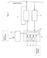
- the device for injecting a drug dosed amount into the skin of a patient is that they are from an injection delivery system (Fig.1), which is a sensor in conjunction with an internal Information processing unit 74 controls itself, in which Information processing unit, a register 77 for the QUANTITY and a register 76 for which TIMES are saved.
- a quantity-time control for a programmed one Injection sequence ensures and data transmission via a transmission module 70 an external central office 78 and communication of the central office for the purpose Change of register contents and change of the program flow in the device and a two-way voice connection via a mobile telephone circuit, e.g. via a D 1 or D2 network, between an external central unit and the patient can.
- the device there is not only the possibility of a programmed and self-controlling injection, but also an external one Monitoring of a patient by medical personnel and an external change of the program sequences and change of the register contents in the on the body Contraption.
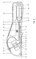
- the device (Fig.2) consists mainly of a small compact and Body portable unit that has a low energy requirement, over one closed fluid area for the therapeutic agent, all other assemblies, like drive 4 for the injection cannula 3, conveyor device 7 for the liquid Therapeutic, actuators for valves, sensor and measuring points, only outside the Fluid flow are arranged and thus not in contact with the therapeutic agent come and thus meet the aseptic requirements for such a device.
- This closed fluid area in Fig.4; 4.1 recognizable, consists of a structured channel system in a flexible film composite 26, which is essentially from two superimposed, welded or glued foils, e.g. made of polytetrafluoroethylene (PTFE), and chemical against the therapeutic agent is resistant.
- PTFE polytetrafluoroethylene
- the structure of the channel system comprises a depot 6 for the therapeutic agent, one Valve chamber 18, a pump chamber 7, a fluid channel 5.1 and inlet 34 for Refill of the depot and outlet 10 for an injection cannula or needle to be connected 3. After This foil composite 26 can be easily replaced for prolonged use.
- the device (FIG. 2) is on a base plate 1 lying against the patient's body built up.
- the base plate 1 there are at least three, advantageously four, contact sensors 20 used, over the secure flat support of the device on the body surface of the patient is checked. Only with a safe and flat body support the device is put into a ready state.
- the base plate 1 introduced an opening 2 through which an injection needle 3 in acute angle of about 45 to 60 ° can emerge linearly.
- the basic structure of the device thus consists of an inclined Injection needle 3, which is connected to a mechanical linear drive 4.
- the End 3.1 of the injection needle 3 is at the outlet of the fluid area with a fluid line 5 connected to the film composite 26, via which a medicament is passed into the injection needle 3 becomes.
- the fluid line 5 leads to a depot 6, in which e.g. Insoline or something similar Therapeutic agent.
- the pump 7 is operated by the information processing unit 74 controlled so that predetermined in a register QUANTITY quantities of fluid stored or transmitted via a modem and to one in one further register specified time promoted to the output 3.1 of the injection needle 3 become.
- a time-quantity control in the information processing unit ensures that tightly tolerated amounts of fluid at the exit 3.1 of the injection needle 3 for transmission in reach the patient's skin 33.
- For the time-quantity control are at the output Pump 7 at a defined distance a flow meter in a Peltier element 8 and Temperature sensor 9 is arranged. Temperature changes are caused by the Peltier element 8 , e.g. heating or cooling of the therapeutic agent, which are perceived by the temperature element 9 after a time t. About the constant Channel dimensions and the time interval between HOT and COLD of the fluid a measure of the flow velocity and thus of the flow rate is created. The The flow rate that is required for the injection is thus compared in a TARGET-ACTUAL comparison can be measured and controlled with high accuracy via the pump 7.
- a sensor or an impedance measurement is used to check whether the injection needle 3 has actually penetrated the patient's skin.
- a successful injection is checked with the aid of an IR sensor 32, which is integrated in the base plate 1 and faces the injection area of the skin 33.
- the successful injection causes a temperature drop in the skin layer under the IR sensor 32 and provides a signal for recording and for an optical and acoustic display.
- the mechanical linear drive 4 which can move the injection needle 3 at an acute angle out of the base plate 1 of the device, consists of a vibration drive using piezoelectric elements.
- the injection needle 3 is inserted through the opening 2 in the housing base plate 1 to the outside and with its tip 3.1 into the skin 33 and withdrawn again after the injection has taken place.
- a sequence program in the information processing unit controls this drive.
- the linear movement is additionally limited by a mechanical stop.
- the linear drive 4 (FIG. 6) using piezoelectric actuator elements forms a push assembly for the injection needle 3.
- the piezo actuators consist of two clamping rings 43; 44 each with a central bore with the clamping surfaces 43.1; 44.1 for carrying out the injection needle 3 and a sleeve-shaped thrust ring 45 inserted between the clamping rings.
- the end faces 45.1 of the thrust ring 45 are each provided with a side surface of the clamping rings 43; 44 connected, for example glued.
- a voltage U is applied to a clamping ring, its central bore 43.1; 44.1 together and brings about a non-positive connection with the cylindrical surface of the injection needle 3.
- the thrust ring 45 expands and presses the two clamping rings 43; 44 apart. If the piezo actuators are actuated in accordance with the chronological sequence, there is a thrust assembly for a linear movement of the injection needle 3. By changing the phase position of the actuation signals, the injection needle 3 moves backwards.
- 6.1 shows a possible pulse sequence for the activation of the third Piezo actuators 43; 44; 45 shown.
- One of the two clamping rings is with the chassis firmly connected.
- the end of the fluid channel 5.1 is with the depot 6 for the medication connected.
- the depot 6 is filled via a cartridge 11, which was previously in the Device is inserted.
- a contact needle penetrates 12 into the cap 13 e.g. made of natural rubber or latex, the cartridge 11 and establishes the fluid connection 5 between the depot 6 and the cartridge 11. about a manually operated piston 15 we the cartridge 11 before applying the Device emptied to the patient's body.
- the fluid is deposited in the depot 6 transfer.
- a valve 18 provides, among other things. to ensure that the fluid when emptying the Cartridge 11 is not pressed into the fluid channel 5.1 and through the injection needle 3.
- the cartridge 11 can thus remain in the device, with the piston 15 over a punch 16 and button 14 is locked by means of lock 17.
- the Cartridge 11 can also be removed again after being emptied into depot 6 be, with another valve 35 (Fig. 4.1) for a secure closure of the Fluid area ensures.
- the PC interface and the transmit / receive circuit are in an electronic assembly 22 summarized and are located together with the power supply 25, e.g. a Battery, within a housing cover 19, which is connected to the hinge 20 Housing base plate 1 is articulated and closed by means of a lock 17.
- the arrangement of the depot 6 is, for example, in the foreground and parallel to the cartridge 11 shown in more detail.
- the depot 6 (Fig. 4) as part of the Foil composite 26 is made of a flexible, resistant material, e.g. polytetrafluoroethylene (PTFE), which expands out of the cartridge 11 when it is filled.
- the Foil composite 26 consists of at least two foils that are welded together and so the required channels. Form chambers and depots. Depot 6, an overflow channel 27, the valve 18, the pump 7, the fluid channel 5.1 and fluid line 5 go so hanging together into each other. For hygienic or aseptic reasons this film composite 26 is particularly advantageous and as an inexpensive interchangeable element easily exchangeable.
- At the opening points e.g.
- FIG. 4.1 is the further between the holder of the contact needle 12 and the overflow channel 27 Valve 35 is arranged, which is closed after the filling process of the depot 6 and that Channel system seals.
- FIG Cartridge 11 can be removed from the device after the depots 6 have been filled.
- an embodiment of the fluid pump 7 used is closer shown.
- this consists of a pump chamber 36 with an inlet 5.2 and a procedure 5.3.
- the entrance and exit are in and out of the pump chamber 36 designed as a confuser 37 and 38, each with a funnel-shaped cross section.
- the Confusers 37, 38 are directional flow resistances and cause one directional river.
- the channel body 40 with the pump chamber 36 is on the one hand welded to a cover sheet 39 and carries one on the opposite side Piezo disk 42. There is one between the piezo disk 42 and the channel body 40 Metal membrane 41 arranged, which bends when the piezo element is active and a Pressure wave causes.
- a valve 18 (FIGS. 7 and 7.1) is inserted into the fluid channel 5.1.
- the valve 18 has to be closed, for example so that the fluid does not already get into and through the injection needle 3.
- FIG. 4.1 Another valve 35 (Fig. 4.1) is useful in the event that the Cartridge 11 is to be removed from the device again after emptying.
- the valve 35 is opened only when the depots 6 are filled from the cartridge 11.
- Both valves 18; 35 are opened via a piezoelectric actuator 64 or closed.
- the valve 18 In the idle state of the actuator 64, the valve 18 is closed (FIG. 7).
- An inlet opening 48 in a valve chamber 49 of a channel body 40 is thereby closed by a metal membrane 41 covering the valve chamber 49 held by a pressure piece articulated on a prestressed leaf spring 62 51 presses against the metal membrane 41.
- the Metal membrane 41 In the area of the inlet opening 48, the Metal membrane 41 a coating of a sealing material, e.g.
- a Piezoelectric actuator 64 arranged which consists of a stack of piezo elements exists and expands when a voltage is applied and against the leaf spring 62 presses and relieves the metal membrane 41.
- the metal membrane 41 goes into hers Starting position (Fig. 7.1) back and the inlet opening 48 of the valve 18 is again open.
- the valves 18 and 35 are so simple and without any special Controllable energy consumption.
- FIG. 8.2 shows an electrical equivalent circuit diagram for evaluating the correct support of the sensors 20.
- a low voltage U with a frequency f1 of a frequency generator 54 is present at one of the support sensors 20.
- all of the support sensors 20 are connected to an evaluation circuit 56 to 58, which only sends a ready signal when an evaluable signal (FIG. 8) with the frequency f1 is registered at all of the support sensors 20.
- the individual sensors 20 are connected to a preamplifier 56 and a limiter 57, the signals of which are led to an AND gate 58.
- an alternating voltage with the frequency f2 of the frequency generator 55 is applied to the injection needle 3 with a time offset in the process and also evaluated via the support sensors 20 and the evaluation circuit 56 to 58. If an actuation signal is also found at the output of the AND gate 58 during this check, the device is ready and the injection into the patient's skin can begin.
- the signals that can be evaluated are shown in a pulse diagram as they arise with the circuit from FIG. 8.2.
- the device is able to control its functional sequences itself. Error messages are registered, optically or acoustically displayed and reported to the external central point via the transmission module 70.
- the transmission module 70 there is also a cell phone telephone circuit, so that the device can be used to communicate linguistically with the central station via an existing radio network.
Description
Diese Vorrichtung hat den Nachteil einer dauerhaft im Körper des Patienten verweilenden Kanüle und ist deshalb nur einer kleinen Gruppe von Diabetikern vorbehalten. Zur Regulation der Flußmenge ist jeweils eine erneute Voreinstellung des Gerätes erforderlich und gestattet keinen Eingriff bei Abwesenheit. Eine Rückkopplung über das Befinden des Patienten an den Arzt, sowie ein folgender Eingriff durch den Arzt ist nicht vorhanden.
Zum ambulanten Gebrauch sind diese Vorrichtungen nicht geeignet. Darüberhinaus sind sie an eine im Körper verweilende Kanüle gebunden. Eine äußere Eingriffsmöglichkeit durch medizinisches Personal besteht nicht.
das Befinden des Patienten an den Arzt bei örtlicher Abwesenheit des Patienten ist nicht vorhanden. Das Gerät läßt keine Kontrolle über die Eindringtiefe - bei unterschiedlichem Hautwiderstand - und die tatsächlich realisierte Injektionsmenge in die Haut zu. Eine programmierte Eingabe der zu injizierenden Menge ist nicht vorgesehen. Eine äußere bzw. externe Beeinflussung und Überwachung der Gerätefunktionen durch den Arzt oder medizinisches Personal bei örtlicher Distanz des Patienten sind nicht möglich. Das Gerät ist in seiner Handhabung auch nicht für körperlich und geistig Behinderte / Demenzkranke geeignet.
Die Informationsverarbeitungseinheit verfügt dabei über eine Zeit-Mengen-Steuerung z.B. mit einem Register für ZEIT und einem Register für MENGE, und steuert u.a. eine Antriebseinheit für die Injektionskanüle und eine Dosiervorrichtung mit Pumpvorrichtung.
Dieses Material ist chemisch resistent und erfüllt die aseptischen Anforderungen.
Diese Antriebsvorrichtung besteht vorzugsweise aus einem mechanischem Linearantrieb unter Verwendung piezoelektrischer Aktorelemente, die in ihrer Anordnung einen Schubverband für die Injcktionsnadel bilden. Die Piezoaktoren bestehen dabei aus zwei Klemmringen mit je einer mittigen Bohrung zur Durchführung der Injektionsnadel und einem zwischen den Klemmringen eingesetzten hülsenförmigem Schubring. Die Stirnflächen des Schubringes sind jeweils mit einer Seitenfläche der Klemmringe verbunden, z.B. verklebt. Bei Anlegen einer Spannung an einen Klemmring zieht sich dessen mittige Bohrung zusammen und bewirkt mit ihrer Klemmfläche eine kraftschlüssige Verbindung mit der Zylinderfläche der durchgeführten Injektionsnadel. Bei Anlegen einer Spannung an den Schubring erfährt dieser eine Längenausdehnung und drückt mit seinen Stirnflächen die beiden Klemmringe auseinander. Werden die Piezoaktoren in entsprechender zeitlicher Folge angesteuert, ergibt sich ein Schubverband für eine lineare Bewegung der Injektionsnadel. Die Füllung des Depots erfolgt über eine Ladestation in der Vorrichtung, in die eine handelsübliche Kartusche eingelegt wird und deren Inhalt über eine Kontaktnadel und 5 durch manuelle Kolbenbewegung in die Depots übertragen wird.
Weiterer Bestandteil des Übertragungsmoduls ist ein Mobil-Telefon-Schaltkreis für eine wechselseitige Sprachverbindung zwischen Patient und externer Zentralstelle. Der Patient wird vorzugsweise außerdem, falls er innerhalb einer vorgeschriebenen Zeit keine Aktivierung vorgenommen hat, optisch und akustisch auf eine durchzuführende Injektion aufmerksam gemacht.
- Fig. 1
- ein Blockschaltbild für den internen Regelkreis der Vorrichtung und die externe Kommunikation der Vorrichtung über ein Übertragungsmodul mit einer Zentralstelle ;
- Fig. 2
- eine Prinzipdarstellung der Vorrichtung mit der Anordnung der funktionellen Baugruppen und deren Verbindungen;
- Fig. 3
- eine Prinzipdarstellung der Vorrichtung gern. Fig. 2 mit erkennbarer Darstellung des Medikarnenten-Depots;
- Fig. 4
- eine Draufsicht auf das Kanalsystem mit Depots in einem Folienverbund;
- Fig. 4.1
- Draufsicht auf das Kanalsystem gern. Fig. 4 mit Ventil für die Kartuschenentnahme;
- Fig. 5
- eine Draufsicht auf die Kanalstruktur der Infusionspumpe
- Fig. 5.1
- ein Querschnitt der Infusionspumpe gern. Fig. 5;
- Fig. 6
- eine Prinzipdarstellung einer piezoelektrischen Antriebs vorrichtung für die Injektionsnadel;
- Fig. 6.1
- ein Impulsdiagramm für die Ansteuerung der Antriebsvorrichtung gern. Fig. 6;
- Fig. 7
- Querschnitt durch ein Fluidventil gern. Fig. 2 - bei geschlossenem Ventil;
- Fig. 7.1
- Querschnitt durch ein Fluidventil gern. Fig. 2 - bei geöffnetem Ventil;
- Fig. 8
- eine prinzipielle Anordnung einer Sensorik zur Kontrolle der erfolgten Infusion;
- Fig. 8.1
- eine schematische Anordnng der Auflageelektroden, IR-Sensor und Injektionsstelle in der Haut;
- Fig. 8.2
- ein logische Schaltungsanordnung zur Auswertung der Auflagesensoren und der Penetration der Injektionsnadel;
- Fig. 9
- ein Impulsdiagramm für die Auswertung der Signale gem. Fig. 8.2;
Der Linearantrieb 4 (Fig. 6) unter Verwendung piezoelektrischer Aktorelemente bildet in seiner Anordnung einen Schubverband für die Injektionsnadel 3. Die Piezoaktoren bestehen dabei aus zwei Klemmringen 43; 44 mit je einer mittigen Bohrung mit den Klemmflächen 43.1; 44.1 zur Durchführung der Injektionsnadel 3 und einem zwischen den Klemmringen eingesetztem hülsenförmigem Schubring 45. Die Stirnflächen 45.1 des Schubringes 45 sind jeweils mit einer Seitenfläche der Klemmringe 43; 44 verbunden, z.B. verklebt. Bei Anlegen einer Spannung U an einen Klemmring zieht sich dessen mittige Bohrung 43.1; 44.1 zusammen und bewirkt eine kraftschlüssige Verbindung mit der Zylinderfläche der durchgeführten Injektionsnadel 3. Bei Anlegen einer Spannung an den Schubring 45 erfährt dieser eine Längenausdehnung und drückt mit seinen Stirnflächen 45.1 die beiden Klemmringe 43; 44 auseinander. Werden die Piezoaktoren in ent- sprechen der zeitlicher Folge angesteuert, ergibt sich ein Schubverband für eine lineare Bewegung der Injektionsnadel 3. Durch Änderung der Phasenlage der Ansteuersignale erfolgt eine Rückwärtsbewegung der Injektionsnadel 3.
Zur Kontrolle der Penetration der Injektionsnadel 3 wird im Ablauf zeitlich versetzt eine Wechselspannung mit der Freuquenz f2 des Frequenzgenerators 55 an die Injektionsnadel 3 gelegt und ebenfalls über die Auflagesensoren 20 und der Auswerteschaltung 56 bis 58 ausgewertet.
Wird auch bei dieser Kontrolle ein Betätigungssignal am Ausgang des UND-Gatters 58 festgestellt, ist die Bereitschaft der Vorrichtung hergestellt, und die Injektion in die Haut des Patienten kann beginnen.
Mittels der Sensorik ist die Vorrichtung in der Lage, ihre Funktionsabläufe selbst zu kontrollieren. Fehlmeldungen werden registriert, optisch oder akustisch angezeigt und über den Übertragungsmodul 70 an die externe Zentralstelle gemeldet.
Im Übertragungsmodul 70 ist darüberhinaus ein Handy-Telefon-Schaltkreis, so daß mit der Vorrichtung über ein vorhandenes Funknetz sprachlich mit der Zentralstelle kommuniziert werden kann.
Claims (20)
- Vorrichtung zur Injektion eines Medikamentes dosierter Menge mit einem Behälter, einer Injektionskanüle, einer Fördereinrichtung für das Medikament und einem Übertragungsmodul, wobei die Vorrichtung am Körper eines Patienten tragbar ist, gekennzeichnet durch eine räumliche und funktionelle Verbindungeines geschlossenen Fluidiksystems (26) mit von außen am Fluidsystem wirksam angeordneterDosiereinrichtung mit angeschlossenem Depot (6), und einer Befüllstation des Depots (6) aus einer Kartusche (11), sowie einer Fördereinrichtung (7) für das Therapeutikum,eines steuerbaren Antriebes (4) für die Penetration der an das Fluidiksystem lösbar angeschlossenen Injektionskanüle (3),eines Überwachungsmodules (72) mit einer Meßeinrichtung der injizierten Menge, einem Sensorsystem (9;20;20.1;32) zur Kontrolle der Auflage der Vorrichtung auf der Hautoberfläche, zur Kontrolle der Penetration der Injektionsnadel in der Haut und zur Kontrolle der Ausführung der Injektion in Verbindung mit einer Auswerteschaltung,einer Informationsverarbeitungseinheit (74) mit Mikroprozessor (73), Hauptspeicher und einer elektronischen Zeit-Mengen-Steuerung mit Programmspeicher und Registern für MENGE, ZEIT und Sonderfunktionen,eines Übertragungsmodules (70) mit einem GSM (Modem) für die wechselseitige Datenübertragung von Meßwerten , Stellgrößen, Programmänderungen und mit einem Handy-Telefon-Schaltkreis für die separate Sprachverbindung an eine externe Zentralstation.
- Vorrichtung nach Anspruch 1, dadurch gekennzeichnet, daß das in sich geschlossene Fluidiksystem aus einem flexiblen Folienverbund (26) von mindestens zwei strukturierten und übereinanderliegenden fest miteinander verbundenen Folien besteht.
- Vorrichtung nach Anspruch 2, dadurch gekennzeichnet, daß der in sich geschlossene Folienverbund (26) verschweißt ist und aus Polytetrafluoräthylen besteht.
- Vorrichtung nach Anspruch 1, dadurch gekennzeichnet, daß die Dosiereinrichtung aus einer gesteuerten piezoelektrischen Mikropumpe (7), angeordnet an einem Fluidkanal (5.1) und zwischen einem Medikament-Depot (6) und der Injektionskanüle (3), besteht, wobei der piezoelektrischen Mikropumpe (7) ein Flußmesser für den SOLL-IST-Vergleich der Zeit-Mengen-Steuerung nachgeordnet ist .
- Vorrichtung nach Anspruch 1 bis 4, dadurch gekennzeichnet, daß der Fluidkanal (5.1) mit angeschlossener Mikropumpe (7) und Flußmessung mit der sich anschließenden flexiblen Fluidleitung (5) für den Anschluß der Injektionskanüle (3) und dem Medika - menten-Depot (6) als geschlossenes Fluidiksystem ausgebildet, austauschbar ist.
- Vorrichtung nach Anspruch 5, dadurch gekennzeichnet, daß das geschlossene Fluidiksystem am Einlauf eine Halterung (34) für eine Kontaktnadel (12) und am Auslauf der Fluidleitung (5) eine Halterung (10) für den Anschluß einer Injektionskanüle (3) aufweist.
- Vorrichtung nach Anspruch 6, dadurch gekennzeichnet, daß die Kontakt nadel (12) beim Einlegen einer Kartusche (11) in eine elastische Verschlußkappe (13) der Kartusche (11) abdichtend eindringt.
- Vorrichtung nach Anspruch 7, dadurch gekennzeichnet, daß die Verschluß kappe (13) der Kartusche (11) aus Naturkautschuk besteht.
- Vorrichtung nach Anspruch 2, dadurch gekennzeichnet, daß die Flußmessung für die zu fördernde Medikamenten-Menge durch die Anordnung eines Temperatursensors (9) und eines Peltierelementes (8) realisiert ist, die in definiertem Abstand am Ausgang der Mikropumpe (7) angeordent sind.
- Vorrichtung nach Anspruch 1 bis 5, dadurch gekennzeichnet, daß der Mikropumpe (7) ein Einlaßventil (18) vorgeschaltet ist und die Pumpkammer der Mikropumpe (7) und Ventilkammer des Einlaßventils (18) in einem Kanalkörper (40) strukturiert ein geformt sind.
- Vorrichtung nach Anspruch 10, dadurch gekennzeichnet, dass der Mikropumpe (7) am Zulauf und am Ablauf Konfuser (37; 38) als richtungsbezogene Strömungswiderstände zugeordnet sind.
- Vorrichtung nach Anspruch 1, dadurch gekennzeichnet, dass der Antrieb für die Injektionskanüle (3) ein Linearantrieb ist, der aus einem Schubverband von piezoelektrischen Aktoren besteht, an die in einer programmierten Steuerfolge eine Spannung U angelegt wird und die Injektionskanüle (3) linear im spitzem Winkel aus einer Öffnung (2) der Gehäusegrundplatte (1) führt.
- Vorrichtung nach Anspruch 12, dadurch gekennzeichnet, dass der spitze Winkel für den Austritt der Injektionskanüle (3) aus der Vorrichtung 45 bis 60° beträgt.
- Vorrichtung nach Anspruch 13, dadurch gekennzeichnet, dass der aus piezo-elektrischen Aktoren bestehende Schubverband aus zwei Klemmringen (43; 44) und einem zwischen den Klemmringen (43; 44) liegendem Schubring (45) besteht, wobei die Klemmringe eine mittige Bohrung (43.1; 44.1) mit Klemmflächen (43.1; 44.1) zur Durchführung der Injektionskanüle (3) aufweisen, wobei ein Klemmring fest am Chassis angeordnet ist.
- Vorrichtung nach Anspruch 1, dadurch gekennzeichnet, dass zur Überwachung der Körperauflage mindestens drei Körperelektroden (20) angeordnet sind, deren Signale an eine logische Schaltung (56 bis 58) geführt sind, die bei Körperauflage ein Bereitschaftssignal an die Informationsverarbeitungseinheit (74) sendet.
- Vorrichtung nach Anspruch 15, dadurch gekennzeichnet, dass an eine der Körperelektroden (20) eine Wechselspannung mit der Frequenz f1 geführt ist, die über die weiteren Körperelektroden (20) übertragen und als Einzelsignale über Vor verstärker (56), Begrenzer (57) an eine UND-Verknüpfung (58) geführt sind.
- Vorrichtung nach Anspruch 16, dadurch gekennzeichnet, dass an die Injektionskanüle (3) eine Wechselspannung mit der Frequenz f2 geführt ist, die zeitlich versetzt über alle Körperelektroden (20) übertragen und als Einzelsignale über Vorverstärker (56), Begrenzer (57) an die UND-Verknüpfung (58) geführt sind.
- Vorrichtung nach Anspruch 1, dadurch gekennzeichnet, dass die in der Informationsverarbeitungsanlage gespeicherten Programme und die Inhalte der Register MENGE, ZEIT und Sonderfunktionen über das GSM des Übertragungsmoduls (70) von einer externen Zentralstelle änderbar sind , sowie die Informationsverarbeitungsanlage Eingänge für die Sensorsignale aufweist.
- Vorrichtung nach Anspruch 15, dadurch gekennzeichnet, dass ein Auflagesensor (20) mit einem Frequenzgenerator mit der Frequenz f1 in Verbindung steht, die von allen Auflagesensoren an eine Auswerteschaltung übertragen wird und über Vorverstärker (56), Begrenzer (57) und UND-Gatter ein Ausgangssignal bildet.
- Vorrichtung nach Anspruch 19, dadurch gekennzeichnet, daß die Injektionskanüle (3) mit einem Frequenzgenerator mit der Frequenz f2 in Verbindung steht, die von allen Auflagesensoren (20) empfangen wird und diese über Vorverstärker (56) und Begrenzer (57) als Ausgangssignale an die Auswerteschaltung weiterleitet.
Applications Claiming Priority (2)
| Application Number | Priority Date | Filing Date | Title |
|---|---|---|---|
| DE10004496 | 2000-02-02 | ||
| DE10004496A DE10004496A1 (de) | 2000-02-02 | 2000-02-02 | Vorrichtung und Verfahren zur Injektion eines Medikamentes |
Publications (3)
| Publication Number | Publication Date |
|---|---|
| EP1170024A2 EP1170024A2 (de) | 2002-01-09 |
| EP1170024A3 EP1170024A3 (de) | 2002-01-16 |
| EP1170024B1 true EP1170024B1 (de) | 2003-10-29 |
Family
ID=7629548
Family Applications (1)
| Application Number | Title | Priority Date | Filing Date |
|---|---|---|---|
| EP01102303A Expired - Lifetime EP1170024B1 (de) | 2000-02-02 | 2001-02-01 | Vorrichtung zur Injektion eines Medikamentes |
Country Status (3)
| Country | Link |
|---|---|
| EP (1) | EP1170024B1 (de) |
| AT (1) | ATE252922T1 (de) |
| DE (2) | DE10004496A1 (de) |
Cited By (1)
| Publication number | Priority date | Publication date | Assignee | Title |
|---|---|---|---|---|
| US9457147B2 (en) | 2005-06-16 | 2016-10-04 | Novo Nordisk A/S | Method and apparatus for assisting patients in self-administration of medication |
Families Citing this family (11)
| Publication number | Priority date | Publication date | Assignee | Title |
|---|---|---|---|---|
| DE10051576A1 (de) * | 2000-02-01 | 2002-02-21 | Disetronic Licensing Ag | Konfigurierbare Vorrichtung und Verfahren zur Abgabe einer Substanz |
| SE0102694L (sv) * | 2001-08-08 | 2003-02-09 | Rosengren Teknik Ab | Personligt hjälpmedel för hantering av medicin |
| US6602229B2 (en) * | 2001-08-24 | 2003-08-05 | Ronald G. Coss | Vibrating injection needle |
| DE10219675A1 (de) * | 2002-05-02 | 2003-11-20 | Thomas Simon | Mobiles Kommunikationsgerät |
| DE102007055635A1 (de) | 2007-11-21 | 2009-05-28 | Robert Bosch Gmbh | System zum Verabreichen eines flüssigen Medikaments |
| US9782538B2 (en) | 2012-09-27 | 2017-10-10 | Becton, Dickinson And Company | Angled inserter for drug infusion |
| DE202013000411U1 (de) * | 2013-01-16 | 2013-01-24 | H & B Electronic Gmbh & Co. Kg | Dauerinfusionsvorrichtung |
| US10080839B2 (en) | 2013-03-14 | 2018-09-25 | Becton, Dickinson And Company | Angled inserter for drug infusion |
| US9821113B2 (en) | 2013-03-15 | 2017-11-21 | Becton, Dickinson And Company | Automatic angled infusion set assembly |
| DE102015225842A1 (de) * | 2015-12-18 | 2017-06-22 | Robert Bosch Gmbh | Überwachungseinheit für eine Medikamentenabgabevorrichtung und Verfahren zum Erzeugen eines Alarmsignals |
| USD853583S1 (en) | 2017-03-29 | 2019-07-09 | Becton, Dickinson And Company | Hand-held device housing |
Family Cites Families (4)
| Publication number | Priority date | Publication date | Assignee | Title |
|---|---|---|---|---|
| GB9606829D0 (en) * | 1996-03-30 | 1996-06-05 | Jeffrey Peter | Supplying materials etc |
| US5860957A (en) * | 1997-02-07 | 1999-01-19 | Sarcos, Inc. | Multipathway electronically-controlled drug delivery system |
| WO1999032174A1 (de) * | 1997-12-19 | 1999-07-01 | Arithmed Gmbh | Tragbarer medikamentspender zur zeitversetzten verabreichung von injektions- oder infusionspräparaten |
| DE19825898A1 (de) * | 1998-06-10 | 1998-12-10 | Ditec Gmbh | Vorrichtung zur Aufzeichnung und Übertragung digitalisierter EKG-Daten |
-
2000
- 2000-02-02 DE DE10004496A patent/DE10004496A1/de not_active Withdrawn
-
2001
- 2001-02-01 EP EP01102303A patent/EP1170024B1/de not_active Expired - Lifetime
- 2001-02-01 DE DE50100857T patent/DE50100857D1/de not_active Expired - Lifetime
- 2001-02-01 AT AT01102303T patent/ATE252922T1/de not_active IP Right Cessation
Cited By (1)
| Publication number | Priority date | Publication date | Assignee | Title |
|---|---|---|---|---|
| US9457147B2 (en) | 2005-06-16 | 2016-10-04 | Novo Nordisk A/S | Method and apparatus for assisting patients in self-administration of medication |
Also Published As
| Publication number | Publication date |
|---|---|
| EP1170024A3 (de) | 2002-01-16 |
| DE10004496A1 (de) | 2000-08-03 |
| EP1170024A2 (de) | 2002-01-09 |
| ATE252922T1 (de) | 2003-11-15 |
| DE50100857D1 (de) | 2003-12-04 |
Similar Documents
| Publication | Publication Date | Title |
|---|---|---|
| EP0951308B1 (de) | Medikamenten-dosiersystem | |
| EP1170024B1 (de) | Vorrichtung zur Injektion eines Medikamentes | |
| EP1749548B1 (de) | Spender für Medien | |
| EP3012600B1 (de) | Dosiervorrichtung für ein infusionssystem | |
| EP1221992B1 (de) | Vorrichtung zur dosierten verabreichung eines injizierbaren produkts | |
| EP1834658B1 (de) | Peristaltische Mikropumpe mit Volumenstromsensor | |
| EP0642802B1 (de) | Inhalationsgerät | |
| EP1448252B1 (de) | Medizinische pumpvorrichtung | |
| DE60132909T2 (de) | Implantierbare medizinische vorrichtung zum abgeben einer flüssigkeit | |
| DE69214457D1 (de) | DOSIERVORRICHTUNG FüR EIN IMPLANTIERBARES SYSTEM ZUR ABGABE VON MEDIKAMENTEN | |
| DE3025452A1 (de) | Durchflussregel-kassette und regler dafuer | |
| DE2513467B2 (de) | Gerät zur Infusion von Flüssigkeiten in den menschlichen oder tierischen Körper | |
| DE10300896A1 (de) | Automatische, von Hydrogelen getriebene Fördereinrichtung mit einstellbarer Abgabecharakteristik zum Fördern eines Mediums, insbesondere Insulin | |
| EP1467782B1 (de) | Implantierbare infusionspumpe | |
| DE2552446C3 (de) | Gerät zur Infusion von Flüssigkeiten in den menschlichen oder tierischen Körper | |
| EP4192555A1 (de) | Nasenapplikator | |
| EP1649252B1 (de) | Vorrichtung und verfahren zum dosierten ausbringen eines viskosen mediums | |
| EP1531888B1 (de) | Infusionspumpe zur dosierten verabreichung einer medizinischen flüssigkeit | |
| DE102015224624B3 (de) | Freistrahldosiersystem zur Verabreichung eines Fluids in oder unter die Haut | |
| WO1999032174A1 (de) | Tragbarer medikamentspender zur zeitversetzten verabreichung von injektions- oder infusionspräparaten | |
| DE2051639A1 (de) | Intravenöse Infusionsvorrichtung | |
| EP2535071A1 (de) | Medikationsvorrichtung zur dosierten Abgabe eines fluiden Mediums | |
| DE19853035A1 (de) | Tragbares Mikrodosiersystem zur zeitverzögerten Abgabe von Flüssigkeiten | |
| DE19818646A1 (de) | Infusionsvorrichtung sowie Verfahren zur Förderung einer Flüssigkeit und Vorrichtung zur Durchführung des Verfahrens | |
| DE4300551A1 (en) | Device for filling body hollow organs with physiologically acceptable gas - involves small pressure container filled with highly clean, sterile and pressurised gas, with outlet which can be cut off. |
Legal Events
| Date | Code | Title | Description |
|---|---|---|---|
| PUAI | Public reference made under article 153(3) epc to a published international application that has entered the european phase |
Free format text: ORIGINAL CODE: 0009012 |
|
| PUAL | Search report despatched |
Free format text: ORIGINAL CODE: 0009013 |
|
| AK | Designated contracting states |
Kind code of ref document: A2 Designated state(s): AT BE CH CY DE DK ES FI FR GB GR IE IT LI LU MC NL PT SE TR |
|
| AX | Request for extension of the european patent |
Free format text: AL;LT;LV;MK;RO;SI |
|
| AK | Designated contracting states |
Kind code of ref document: A3 Designated state(s): AT BE CH CY DE DK ES FI FR GB GR IE IT LI LU MC NL PT SE TR |
|
| AX | Request for extension of the european patent |
Free format text: AL;LT;LV;MK;RO;SI |
|
| 17P | Request for examination filed |
Effective date: 20020625 |
|
| AKX | Designation fees paid |
Free format text: AT BE CH CY DE DK ES FI FR GB GR IE IT LI LU MC NL PT SE TR |
|
| 17Q | First examination report despatched |
Effective date: 20021114 |
|
| RAP1 | Party data changed (applicant data changed or rights of an application transferred) |
Owner name: LAMSTER, JOERG, DR. MED. |
|
| GRAH | Despatch of communication of intention to grant a patent |
Free format text: ORIGINAL CODE: EPIDOS IGRA |
|
| RTI1 | Title (correction) |
Free format text: DEVICE FOR THE INJECTION OF A MEDICAMENT |
|
| GRAS | Grant fee paid |
Free format text: ORIGINAL CODE: EPIDOSNIGR3 |
|
| GRAA | (expected) grant |
Free format text: ORIGINAL CODE: 0009210 |
|
| AK | Designated contracting states |
Kind code of ref document: B1 Designated state(s): AT BE CH CY DE DK ES FI FR GB GR IE IT LI LU MC NL PT SE TR |
|
| PG25 | Lapsed in a contracting state [announced via postgrant information from national office to epo] |
Ref country code: TR Free format text: LAPSE BECAUSE OF FAILURE TO SUBMIT A TRANSLATION OF THE DESCRIPTION OR TO PAY THE FEE WITHIN THE PRESCRIBED TIME-LIMIT Effective date: 20031029 Ref country code: IE Free format text: LAPSE BECAUSE OF FAILURE TO SUBMIT A TRANSLATION OF THE DESCRIPTION OR TO PAY THE FEE WITHIN THE PRESCRIBED TIME-LIMIT Effective date: 20031029 Ref country code: CY Free format text: LAPSE BECAUSE OF FAILURE TO SUBMIT A TRANSLATION OF THE DESCRIPTION OR TO PAY THE FEE WITHIN THE PRESCRIBED TIME-LIMIT Effective date: 20031029 Ref country code: FI Free format text: LAPSE BECAUSE OF FAILURE TO SUBMIT A TRANSLATION OF THE DESCRIPTION OR TO PAY THE FEE WITHIN THE PRESCRIBED TIME-LIMIT Effective date: 20031029 Ref country code: NL Free format text: LAPSE BECAUSE OF FAILURE TO SUBMIT A TRANSLATION OF THE DESCRIPTION OR TO PAY THE FEE WITHIN THE PRESCRIBED TIME-LIMIT Effective date: 20031029 |
|
| REG | Reference to a national code |
Ref country code: GB Ref legal event code: FG4D Free format text: NOT ENGLISH |
|
| REG | Reference to a national code |
Ref country code: CH Ref legal event code: EP |
|
| REG | Reference to a national code |
Ref country code: IE Ref legal event code: FG4D Free format text: GERMAN |
|
| REF | Corresponds to: |
Ref document number: 50100857 Country of ref document: DE Date of ref document: 20031204 Kind code of ref document: P |
|
| PG25 | Lapsed in a contracting state [announced via postgrant information from national office to epo] |
Ref country code: GR Free format text: LAPSE BECAUSE OF FAILURE TO SUBMIT A TRANSLATION OF THE DESCRIPTION OR TO PAY THE FEE WITHIN THE PRESCRIBED TIME-LIMIT Effective date: 20040129 Ref country code: DK Free format text: LAPSE BECAUSE OF FAILURE TO SUBMIT A TRANSLATION OF THE DESCRIPTION OR TO PAY THE FEE WITHIN THE PRESCRIBED TIME-LIMIT Effective date: 20040129 |
|
| PG25 | Lapsed in a contracting state [announced via postgrant information from national office to epo] |
Ref country code: LU Free format text: LAPSE BECAUSE OF NON-PAYMENT OF DUE FEES Effective date: 20040201 Ref country code: AT Free format text: LAPSE BECAUSE OF NON-PAYMENT OF DUE FEES Effective date: 20040201 |
|
| PG25 | Lapsed in a contracting state [announced via postgrant information from national office to epo] |
Ref country code: ES Free format text: LAPSE BECAUSE OF FAILURE TO SUBMIT A TRANSLATION OF THE DESCRIPTION OR TO PAY THE FEE WITHIN THE PRESCRIBED TIME-LIMIT Effective date: 20040209 |
|
| REG | Reference to a national code |
Ref country code: SE Ref legal event code: TRGR |
|
| PGFP | Annual fee paid to national office [announced via postgrant information from national office to epo] |
Ref country code: SE Payment date: 20040224 Year of fee payment: 4 |
|
| GBT | Gb: translation of ep patent filed (gb section 77(6)(a)/1977) |
Effective date: 20040204 |
|
| PG25 | Lapsed in a contracting state [announced via postgrant information from national office to epo] |
Ref country code: MC Free format text: LAPSE BECAUSE OF NON-PAYMENT OF DUE FEES Effective date: 20040228 Ref country code: BE Free format text: LAPSE BECAUSE OF NON-PAYMENT OF DUE FEES Effective date: 20040228 |
|
| NLV1 | Nl: lapsed or annulled due to failure to fulfill the requirements of art. 29p and 29m of the patents act | ||
| REG | Reference to a national code |
Ref country code: IE Ref legal event code: FD4D |
|
| ET | Fr: translation filed | ||
| BERE | Be: lapsed |
Owner name: *LAMSTER JORG Effective date: 20040228 |
|
| PLBE | No opposition filed within time limit |
Free format text: ORIGINAL CODE: 0009261 |
|
| STAA | Information on the status of an ep patent application or granted ep patent |
Free format text: STATUS: NO OPPOSITION FILED WITHIN TIME LIMIT |
|
| 26N | No opposition filed |
Effective date: 20040730 |
|
| PG25 | Lapsed in a contracting state [announced via postgrant information from national office to epo] |
Ref country code: SE Free format text: LAPSE BECAUSE OF NON-PAYMENT OF DUE FEES Effective date: 20050202 |
|
| EUG | Se: european patent has lapsed | ||
| PGFP | Annual fee paid to national office [announced via postgrant information from national office to epo] |
Ref country code: IT Payment date: 20060228 Year of fee payment: 6 |
|
| PG25 | Lapsed in a contracting state [announced via postgrant information from national office to epo] |
Ref country code: PT Free format text: LAPSE BECAUSE OF NON-PAYMENT OF DUE FEES Effective date: 20040329 |
|
| PGFP | Annual fee paid to national office [announced via postgrant information from national office to epo] |
Ref country code: CH Payment date: 20080225 Year of fee payment: 8 Ref country code: FR Payment date: 20070216 Year of fee payment: 7 |
|
| REG | Reference to a national code |
Ref country code: FR Ref legal event code: ST Effective date: 20081031 |
|
| PG25 | Lapsed in a contracting state [announced via postgrant information from national office to epo] |
Ref country code: FR Free format text: LAPSE BECAUSE OF NON-PAYMENT OF DUE FEES Effective date: 20080229 |
|
| PG25 | Lapsed in a contracting state [announced via postgrant information from national office to epo] |
Ref country code: IT Free format text: LAPSE BECAUSE OF NON-PAYMENT OF DUE FEES Effective date: 20070201 |
|
| REG | Reference to a national code |
Ref country code: CH Ref legal event code: PL |
|
| PG25 | Lapsed in a contracting state [announced via postgrant information from national office to epo] |
Ref country code: LI Free format text: LAPSE BECAUSE OF NON-PAYMENT OF DUE FEES Effective date: 20090228 Ref country code: CH Free format text: LAPSE BECAUSE OF NON-PAYMENT OF DUE FEES Effective date: 20090228 |
|
| PGFP | Annual fee paid to national office [announced via postgrant information from national office to epo] |
Ref country code: GB Payment date: 20110523 Year of fee payment: 11 |
|
| PGFP | Annual fee paid to national office [announced via postgrant information from national office to epo] |
Ref country code: DE Payment date: 20110527 Year of fee payment: 11 |
|
| GBPC | Gb: european patent ceased through non-payment of renewal fee |
Effective date: 20120201 |
|
| REG | Reference to a national code |
Ref country code: DE Ref legal event code: R119 Ref document number: 50100857 Country of ref document: DE Effective date: 20120901 |
|
| PG25 | Lapsed in a contracting state [announced via postgrant information from national office to epo] |
Ref country code: GB Free format text: LAPSE BECAUSE OF NON-PAYMENT OF DUE FEES Effective date: 20120201 |
|
| PG25 | Lapsed in a contracting state [announced via postgrant information from national office to epo] |
Ref country code: DE Free format text: LAPSE BECAUSE OF NON-PAYMENT OF DUE FEES Effective date: 20120901 |