EP1167991A2 - Verfahren und Vorrichtung zur Richtungserkennung von gepulsten Laserstrahlen nach dem Zeitintervallprinzip - Google Patents
Verfahren und Vorrichtung zur Richtungserkennung von gepulsten Laserstrahlen nach dem Zeitintervallprinzip Download PDFInfo
- Publication number
- EP1167991A2 EP1167991A2 EP01115876A EP01115876A EP1167991A2 EP 1167991 A2 EP1167991 A2 EP 1167991A2 EP 01115876 A EP01115876 A EP 01115876A EP 01115876 A EP01115876 A EP 01115876A EP 1167991 A2 EP1167991 A2 EP 1167991A2
- Authority
- EP
- European Patent Office
- Prior art keywords
- time interval
- time
- charging
- discharging
- incidence
- Prior art date
- Legal status (The legal status is an assumption and is not a legal conclusion. Google has not performed a legal analysis and makes no representation as to the accuracy of the status listed.)
- Granted
Links
Images


Classifications
-
- G—PHYSICS
- G01—MEASURING; TESTING
- G01S—RADIO DIRECTION-FINDING; RADIO NAVIGATION; DETERMINING DISTANCE OR VELOCITY BY USE OF RADIO WAVES; LOCATING OR PRESENCE-DETECTING BY USE OF THE REFLECTION OR RERADIATION OF RADIO WAVES; ANALOGOUS ARRANGEMENTS USING OTHER WAVES
- G01S3/00—Direction-finders for determining the direction from which infrasonic, sonic, ultrasonic or electromagnetic waves, or particle emission, not having a directional significance, are being received
- G01S3/78—Direction-finders for determining the direction from which infrasonic, sonic, ultrasonic or electromagnetic waves, or particle emission, not having a directional significance, are being received using electromagnetic waves other than radio waves
- G01S3/782—Systems for determining direction or deviation from predetermined direction
Definitions
- the invention relates to a method for detecting the direction of pulsed laser beams according to the time interval measurement principle, the direction of incidence as the time of flight in glass fibers of different lengths between the receiving optics and a detector is measured by means of a digital time interval measuring circuit and devices its implementation.
- pulsed lasers are used to determine distances, Target lighting, glare from sensors and missile guidance are used. It is mostly radiation in invisible, infrared spectral transparency areas of the Atmosphere of 0.7-1.5 ⁇ m, 3 - 5 ⁇ m or 8-12 ⁇ m is used.
- the pulse width varies after application between 1-200 ns, the pulse repetition frequency from a few Hertz up to the megahertz range.
- the sensors that are most often used around the direction of incidence of the pulsed Detecting rows are detector rows and arrays. With the help of an upstream
- the receiving optics are the axes of the different directions of incidence assigned different location coordinates on the sensor.
- the entire reception angle e.g. one Celestial quadrants include, in a number of angular fields with separate receiving optics divided, each similar to the compound eye of insects a small Take up an angle section, with neighboring fields partially overlapping. each Individual optics bundle the incident laser light into a glass fiber that is used by neighboring ones Optics are of different lengths, but are all grouped together at their second end be directed to a common detector.
- An incident laser radiation then differs depending on the direction of incidence long way back along the glass fiber to the detector, which corresponds to the angular difference of the Direction of view of the individual eyes corresponds. So that the direction of incidence is defined as one Time span can be measured, there must also be a reference time for all Individual optics can be measured together.
- the direction of incidence is identified by measurement the time span between the detection of the common time of the arriving Laser pulses and the detection of the second one depending on the direction of incidence in azimuth, or the third pulse depending on the direction of incidence in elevation dependent laser pulse.
- the clock frequency can only be increased to a limited extent, since current digital modules only can process a limited high clock frequency.
- the Power consumption at higher clock frequencies increases dramatically and the susceptibility to interference significantly higher.
- the disadvantages mentioned are eliminated in that the direction-dependent time interval first electronically stretched by a known factor before it is forwarded to digitization. This can while maintaining the previous digitization circuit and the previous delay lengths the Direction resolution significantly improved or with the same direction resolution The complexity of the previous systems can be reduced. So it can either be shorter Delay lines selected and / or the clock frequency for digitization reduced become.
- the accuracy of the time extension depends very much on the constant currents.
- the current switch consists of the emitter-coupled transistors T3 and T4.
- the Charging current is from a constant current source consisting of a voltage reference ZN1, the operational amplifier OP1B and the transistor T1 generated.
- the discharge current will from the current mirror, consisting of the Zener diode Z2, the capacitor C2, the Operational amplifier OP2B and the transistor T2 generated.
- the current mirror circuit ensures that if there is a change in the charging current, for example Environmental influences or due to aging of the discharge current is changed to the same extent. As a result, the time span remains unaffected by the change in current.
Landscapes
- Physics & Mathematics (AREA)
- Electromagnetism (AREA)
- Engineering & Computer Science (AREA)
- General Physics & Mathematics (AREA)
- Radar, Positioning & Navigation (AREA)
- Remote Sensing (AREA)
- Optical Radar Systems And Details Thereof (AREA)
- Photometry And Measurement Of Optical Pulse Characteristics (AREA)
Abstract
Description
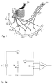
- Fig. 1
- eine schematische Darstellung einer bekannten Empfangsvorrichtung für Laserstrahlung,
- Fig. 2a
- das Schaltungsprinzip für das erfindungsgemäße Verfahren"
- Fig. 2b
- ein Diagramm zum erfindungsgemäßen Verfahren,
- Fig. 3
- ein Diagramm zu einer vereinfachten Variante des erfindungsgemäßen Verfahrens,
- Fig. 4
- eine schematische Darstellung einer Stromspiegel-Schaltung zur Durchführung des erfindungsgemäßen Verfahrens.
Claims (5)
- Verfahren zur Richtungserkennung von gepulsten Laserstrahlen nach dem Zeitintervallmeßprinzip, wobei die Einfallsrichtung als Lichtlaufzeit in unterschiedlich langen Glasfasern zwischen einer Empfangsoptik und einem Detektor mittels einer digitalen Zeitintervallmeßschaltung gemessen wird, dadurch gekennzeichnet, daß das richtungbestimmende Zeitintervall vor der Digitalisierung elektronisch gestreckt wird.
- Verfahren nach Anspruch 1, dadurch gekennzeichnet, daß die Zeitstreckung durch Auf- und Entladung eines Kondensators mit definierten Konstantströmen erfolgt.
- Verfahren nach Anspruch 1 und 2, dadurch gekennzeichnet, daß als Meßgröße das Gesamtzeitintervall der Auf- und Entladung des Konsators verwendet wird.
- Verfahren nach einem der vorhergehenden Ansprüche, dadurch gekennzeichnet, daß an einem Komparator eine Vorschwelle so eingestellt wird, daß Zeitverzögerungen im Komparatorschaltvorgang durch die unterschiedlichen Flankensteilheiten kompensiert werden.
- Verfahren nach Anspruch 1 und 2, dadurch gekennzeichnet, daß mittels einer Stromspiegelschaltung der Entladestrom vom Ladestrom abgeleitet wird, so daß Ladestromänderungen automatisch kompensiert werden.
Applications Claiming Priority (2)
| Application Number | Priority Date | Filing Date | Title |
|---|---|---|---|
| DE10032162 | 2000-07-01 | ||
| DE10032162A DE10032162C1 (de) | 2000-07-01 | 2000-07-01 | Verfahren und Vorrichtung zur Richtungserkennung von gepulsten Laserstrahlen nach dem Zeitintervallmeßprinzip |
Publications (3)
| Publication Number | Publication Date |
|---|---|
| EP1167991A2 true EP1167991A2 (de) | 2002-01-02 |
| EP1167991A3 EP1167991A3 (de) | 2002-03-06 |
| EP1167991B1 EP1167991B1 (de) | 2004-03-31 |
Family
ID=7647523
Family Applications (1)
| Application Number | Title | Priority Date | Filing Date |
|---|---|---|---|
| EP01115876A Expired - Lifetime EP1167991B1 (de) | 2000-07-01 | 2001-06-29 | Verfahren und Vorrichtung zur Richtungserkennung von gepulsten Laserstrahlen nach dem Zeitintervallprinzip |
Country Status (2)
| Country | Link |
|---|---|
| EP (1) | EP1167991B1 (de) |
| DE (2) | DE10032162C1 (de) |
Cited By (3)
| Publication number | Priority date | Publication date | Assignee | Title |
|---|---|---|---|---|
| RU2334243C1 (ru) * | 2006-11-08 | 2008-09-20 | Федеральное государственное унитарное предприятие "Производственное объединение "Уральский оптико-механический завод" имени Э.С. Яламова" | Устройство обнаружения лазерного облучения |
| US8110791B2 (en) | 2007-08-16 | 2012-02-07 | Bae Systems Plc | Imaging device |
| CN114428225A (zh) * | 2022-04-06 | 2022-05-03 | 中国电子科技集团公司第二十九研究所 | 一种基于准匹配滤波的多辐射源到达角度测量方法及装置 |
Families Citing this family (1)
| Publication number | Priority date | Publication date | Assignee | Title |
|---|---|---|---|---|
| RU2231080C1 (ru) * | 2003-03-24 | 2004-06-20 | Военно-Космическая Академия | Оптический пеленгатор |
Family Cites Families (4)
| Publication number | Priority date | Publication date | Assignee | Title |
|---|---|---|---|---|
| DE3323828C2 (de) * | 1983-07-01 | 1986-01-16 | Messerschmitt-Bölkow-Blohm GmbH, 8012 Ottobrunn | Laserwarnsensor |
| DE3525518A1 (de) * | 1984-12-20 | 1986-07-10 | Messerschmitt-Bölkow-Blohm GmbH, 8012 Ottobrunn | Laserwarnsensor mit richtungserkennung |
| EP0283538B1 (de) * | 1987-03-26 | 1990-08-16 | Messerschmitt-Bölkow-Blohm Gesellschaft mit beschränkter Haftung | Detektorvorrichtung |
| US5784156A (en) * | 1996-11-19 | 1998-07-21 | Tracor Aerospace, Inc. | Fiber optic guidance system for laser guided missiles |
-
2000
- 2000-07-01 DE DE10032162A patent/DE10032162C1/de not_active Expired - Fee Related
-
2001
- 2001-06-29 EP EP01115876A patent/EP1167991B1/de not_active Expired - Lifetime
- 2001-06-29 DE DE50101818T patent/DE50101818D1/de not_active Expired - Lifetime
Cited By (4)
| Publication number | Priority date | Publication date | Assignee | Title |
|---|---|---|---|---|
| RU2334243C1 (ru) * | 2006-11-08 | 2008-09-20 | Федеральное государственное унитарное предприятие "Производственное объединение "Уральский оптико-механический завод" имени Э.С. Яламова" | Устройство обнаружения лазерного облучения |
| US8110791B2 (en) | 2007-08-16 | 2012-02-07 | Bae Systems Plc | Imaging device |
| CN114428225A (zh) * | 2022-04-06 | 2022-05-03 | 中国电子科技集团公司第二十九研究所 | 一种基于准匹配滤波的多辐射源到达角度测量方法及装置 |
| CN114428225B (zh) * | 2022-04-06 | 2022-06-14 | 中国电子科技集团公司第二十九研究所 | 一种基于准匹配滤波的多辐射源到达角度测量方法及装置 |
Also Published As
| Publication number | Publication date |
|---|---|
| DE50101818D1 (de) | 2004-05-06 |
| EP1167991A3 (de) | 2002-03-06 |
| EP1167991B1 (de) | 2004-03-31 |
| DE10032162C1 (de) | 2001-10-11 |
Similar Documents
| Publication | Publication Date | Title |
|---|---|---|
| EP1423731B1 (de) | Verfahren und vorrichtung zur aufnahme eines dreidimensionalen abstandsbildes | |
| DE69716334T2 (de) | Modal-Verarbeitung zur Abstandsmessung mittels Multipulse-Multireturn-Signalen zur Clutter-Beseitigung | |
| DE3215845C1 (de) | Abstandssensor fuer einen Geschosszuender | |
| EP0965117B1 (de) | Vorrichtung und verfahren zum erfassen eines objekts in einem vorgegebenen raumbereich, insbesondere von fahrzeugen für die verkehrsüberwachung | |
| DE3219423A1 (de) | Entfernungsmessverfahren und vorrichtung zu seiner durchfuehrung | |
| EP0283538B1 (de) | Detektorvorrichtung | |
| DE3323828A1 (de) | Laserwarnsensor | |
| DE2923963B1 (de) | Verfahren zur Impulsabstandsmessung und Anordnung zur Durchfuehrung des Verfahrens | |
| DE102015006798A1 (de) | Verfahren und Vorrichtung zur Bilderfassung eines Zielobjektes | |
| EP1288676A1 (de) | Optoelektronische Entfernungsmesseinrichtung | |
| DE2448651A1 (de) | Anordnung zum beruehrungslosen messen der abmessungen eines bewegten messobjekts | |
| DE3020996C2 (de) | Einrichtung zur Bestimmung der Auslöseentfernung von einem sich auf ein Ziel zu bewegenden Flugkörper | |
| DE2723835C2 (de) | Laserentfernungsmeßgerät nach dem Prinzip der Laufzeitmessung eines Lichtimpulses | |
| DE102018203533A1 (de) | Empfangsanordnung zum Empfang von Lichtsignalen und Verfahren zum Empfangen von Lichtsignalen | |
| DE102015217912A1 (de) | Verfahren zur Laufzeitkalibrierung eines Lidarsensors | |
| DE69626611T2 (de) | Schaltung und Verfahren zur Bestimmung der Einfallzeit | |
| DE3886928T2 (de) | Annäherungszünder. | |
| EP1167991B1 (de) | Verfahren und Vorrichtung zur Richtungserkennung von gepulsten Laserstrahlen nach dem Zeitintervallprinzip | |
| DE102016118905A1 (de) | Vorrichtung und Verfahren zum zeitaufgelösten Erfassen gepulster elektromagnetischer Hochfrequenzstrahlung | |
| DE2510537A1 (de) | Verfahren zum schnellen messen des abstandes eines objektes von einer bezugsebene und der geschwindigkeitskomponente des objektes senkrecht zu der bezugsebene | |
| DE3702428A1 (de) | Verfahren und vorrichtung zum messtechnischen erfassen eines projektils oder teilen hiervon | |
| DE2837981C2 (de) | Optisches Zeitbereichs-Reflektometer zur Bestimmung der Dämpfung von Lichtleitfasern | |
| DE2502662A1 (de) | Laser-entfernungsmesser | |
| EP1160536A1 (de) | Laserradar-Annäherungszünder mit Masken-Diskrimination | |
| DE4200057A1 (de) | Lasermesssystem zur messung physikalischer messgroessen |
Legal Events
| Date | Code | Title | Description |
|---|---|---|---|
| PUAI | Public reference made under article 153(3) epc to a published international application that has entered the european phase |
Free format text: ORIGINAL CODE: 0009012 |
|
| AK | Designated contracting states |
Kind code of ref document: A2 Designated state(s): DE FR GB IT Kind code of ref document: A2 Designated state(s): AT BE CH CY DE DK ES FI FR GB GR IE IT LI LU MC NL PT SE TR |
|
| AX | Request for extension of the european patent |
Free format text: AL;LT;LV;MK;RO;SI |
|
| PUAL | Search report despatched |
Free format text: ORIGINAL CODE: 0009013 |
|
| AK | Designated contracting states |
Kind code of ref document: A3 Designated state(s): AT BE CH CY DE DK ES FI FR GB GR IE IT LI LU MC NL PT SE TR |
|
| AX | Request for extension of the european patent |
Free format text: AL;LT;LV;MK;RO;SI |
|
| RIC1 | Information provided on ipc code assigned before grant |
Free format text: 7G 01S 3/781 A, 7G 01S 7/48 B, 7G 01S 3/783 B |
|
| 17P | Request for examination filed |
Effective date: 20020404 |
|
| RAP1 | Party data changed (applicant data changed or rights of an application transferred) |
Owner name: EADS DEUTSCHLAND GMBH |
|
| AKX | Designation fees paid |
Free format text: DE FR GB IT |
|
| GRAP | Despatch of communication of intention to grant a patent |
Free format text: ORIGINAL CODE: EPIDOSNIGR1 |
|
| GRAP | Despatch of communication of intention to grant a patent |
Free format text: ORIGINAL CODE: EPIDOSNIGR1 |
|
| GRAS | Grant fee paid |
Free format text: ORIGINAL CODE: EPIDOSNIGR3 |
|
| GRAA | (expected) grant |
Free format text: ORIGINAL CODE: 0009210 |
|
| AK | Designated contracting states |
Kind code of ref document: B1 Designated state(s): DE FR GB IT |
|
| REG | Reference to a national code |
Ref country code: GB Ref legal event code: FG4D Free format text: NOT ENGLISH |
|
| REG | Reference to a national code |
Ref country code: IE Ref legal event code: FG4D Free format text: GERMAN |
|
| REF | Corresponds to: |
Ref document number: 50101818 Country of ref document: DE Date of ref document: 20040506 Kind code of ref document: P |
|
| GBT | Gb: translation of ep patent filed (gb section 77(6)(a)/1977) |
Effective date: 20040705 |
|
| ET | Fr: translation filed | ||
| REG | Reference to a national code |
Ref country code: IE Ref legal event code: FD4D |
|
| PLBE | No opposition filed within time limit |
Free format text: ORIGINAL CODE: 0009261 |
|
| STAA | Information on the status of an ep patent application or granted ep patent |
Free format text: STATUS: NO OPPOSITION FILED WITHIN TIME LIMIT |
|
| 26N | No opposition filed |
Effective date: 20050104 |
|
| PGFP | Annual fee paid to national office [announced via postgrant information from national office to epo] |
Ref country code: DE Payment date: 20130620 Year of fee payment: 13 Ref country code: GB Payment date: 20130619 Year of fee payment: 13 |
|
| PGFP | Annual fee paid to national office [announced via postgrant information from national office to epo] |
Ref country code: IT Payment date: 20130625 Year of fee payment: 13 Ref country code: FR Payment date: 20130703 Year of fee payment: 13 |
|
| REG | Reference to a national code |
Ref country code: DE Ref legal event code: R119 Ref document number: 50101818 Country of ref document: DE |
|
| GBPC | Gb: european patent ceased through non-payment of renewal fee |
Effective date: 20140629 |
|
| REG | Reference to a national code |
Ref country code: DE Ref legal event code: R119 Ref document number: 50101818 Country of ref document: DE Effective date: 20150101 |
|
| REG | Reference to a national code |
Ref country code: FR Ref legal event code: ST Effective date: 20150227 |
|
| PG25 | Lapsed in a contracting state [announced via postgrant information from national office to epo] |
Ref country code: IT Free format text: LAPSE BECAUSE OF NON-PAYMENT OF DUE FEES Effective date: 20140629 Ref country code: DE Free format text: LAPSE BECAUSE OF NON-PAYMENT OF DUE FEES Effective date: 20150101 |
|
| PG25 | Lapsed in a contracting state [announced via postgrant information from national office to epo] |
Ref country code: GB Free format text: LAPSE BECAUSE OF NON-PAYMENT OF DUE FEES Effective date: 20140629 Ref country code: FR Free format text: LAPSE BECAUSE OF NON-PAYMENT OF DUE FEES Effective date: 20140630 |