EP1167978A1 - Inertialsensor zur Lagerung und Kontrolle einer Inertialreferenz in einem Satelliten - Google Patents
Inertialsensor zur Lagerung und Kontrolle einer Inertialreferenz in einem Satelliten Download PDFInfo
- Publication number
- EP1167978A1 EP1167978A1 EP01112524A EP01112524A EP1167978A1 EP 1167978 A1 EP1167978 A1 EP 1167978A1 EP 01112524 A EP01112524 A EP 01112524A EP 01112524 A EP01112524 A EP 01112524A EP 1167978 A1 EP1167978 A1 EP 1167978A1
- Authority
- EP
- European Patent Office
- Prior art keywords
- optical
- inertial sensor
- sample mass
- sensor according
- measuring sections
- Prior art date
- Legal status (The legal status is an assumption and is not a legal conclusion. Google has not performed a legal analysis and makes no representation as to the accuracy of the status listed.)
- Granted
Links
Images



Classifications
-
- B—PERFORMING OPERATIONS; TRANSPORTING
- B64—AIRCRAFT; AVIATION; COSMONAUTICS
- B64G—COSMONAUTICS; VEHICLES OR EQUIPMENT THEREFOR
- B64G1/00—Cosmonautic vehicles
- B64G1/22—Parts of, or equipment specially adapted for fitting in or to, cosmonautic vehicles
- B64G1/24—Guiding or controlling apparatus, e.g. for attitude control
- B64G1/36—Guiding or controlling apparatus, e.g. for attitude control using sensors, e.g. sun-sensors, horizon sensors
- B64G1/369—Guiding or controlling apparatus, e.g. for attitude control using sensors, e.g. sun-sensors, horizon sensors using gyroscopes as attitude sensors
-
- B—PERFORMING OPERATIONS; TRANSPORTING
- B64—AIRCRAFT; AVIATION; COSMONAUTICS
- B64G—COSMONAUTICS; VEHICLES OR EQUIPMENT THEREFOR
- B64G1/00—Cosmonautic vehicles
- B64G1/22—Parts of, or equipment specially adapted for fitting in or to, cosmonautic vehicles
- B64G1/24—Guiding or controlling apparatus, e.g. for attitude control
- B64G1/242—Orbits and trajectories
-
- B—PERFORMING OPERATIONS; TRANSPORTING
- B64—AIRCRAFT; AVIATION; COSMONAUTICS
- B64G—COSMONAUTICS; VEHICLES OR EQUIPMENT THEREFOR
- B64G1/00—Cosmonautic vehicles
- B64G1/22—Parts of, or equipment specially adapted for fitting in or to, cosmonautic vehicles
- B64G1/24—Guiding or controlling apparatus, e.g. for attitude control
- B64G1/36—Guiding or controlling apparatus, e.g. for attitude control using sensors, e.g. sun-sensors, horizon sensors
-
- G—PHYSICS
- G01—MEASURING; TESTING
- G01P—MEASURING LINEAR OR ANGULAR SPEED, ACCELERATION, DECELERATION, OR SHOCK; INDICATING PRESENCE, ABSENCE, OR DIRECTION, OF MOVEMENT
- G01P15/00—Measuring acceleration; Measuring deceleration; Measuring shock, i.e. sudden change of acceleration
- G01P15/02—Measuring acceleration; Measuring deceleration; Measuring shock, i.e. sudden change of acceleration by making use of inertia forces using solid seismic masses
- G01P15/08—Measuring acceleration; Measuring deceleration; Measuring shock, i.e. sudden change of acceleration by making use of inertia forces using solid seismic masses with conversion into electric or magnetic values
-
- G—PHYSICS
- G01—MEASURING; TESTING
- G01P—MEASURING LINEAR OR ANGULAR SPEED, ACCELERATION, DECELERATION, OR SHOCK; INDICATING PRESENCE, ABSENCE, OR DIRECTION, OF MOVEMENT
- G01P15/00—Measuring acceleration; Measuring deceleration; Measuring shock, i.e. sudden change of acceleration
- G01P15/02—Measuring acceleration; Measuring deceleration; Measuring shock, i.e. sudden change of acceleration by making use of inertia forces using solid seismic masses
- G01P15/08—Measuring acceleration; Measuring deceleration; Measuring shock, i.e. sudden change of acceleration by making use of inertia forces using solid seismic masses with conversion into electric or magnetic values
- G01P15/13—Measuring acceleration; Measuring deceleration; Measuring shock, i.e. sudden change of acceleration by making use of inertia forces using solid seismic masses with conversion into electric or magnetic values by measuring the force required to restore a proofmass subjected to inertial forces to a null position
-
- B—PERFORMING OPERATIONS; TRANSPORTING
- B64—AIRCRAFT; AVIATION; COSMONAUTICS
- B64G—COSMONAUTICS; VEHICLES OR EQUIPMENT THEREFOR
- B64G1/00—Cosmonautic vehicles
- B64G1/10—Artificial satellites; Systems of such satellites; Interplanetary vehicles
- B64G1/1085—Swarms and constellations
-
- B—PERFORMING OPERATIONS; TRANSPORTING
- B64—AIRCRAFT; AVIATION; COSMONAUTICS
- B64G—COSMONAUTICS; VEHICLES OR EQUIPMENT THEREFOR
- B64G1/00—Cosmonautic vehicles
- B64G1/22—Parts of, or equipment specially adapted for fitting in or to, cosmonautic vehicles
- B64G1/24—Guiding or controlling apparatus, e.g. for attitude control
- B64G1/32—Guiding or controlling apparatus, e.g. for attitude control using earth's magnetic field
Definitions
- the invention relates to an inertial sensor as an inertial reference for position and position determination of satellites and satellite parts according to the preamble of Claim 1.
- a new generation of scientific space missions based in particular on high resolution optical instruments requires a very accurate Knowledge of the residual acceleration, the relative positions and location as well as position fluctuations of satellites and parts of satellites.
- the associated degrees of freedom are caused by internal (e.g. shifting the center of gravity or changing the moment of inertia ) and external interference (e.g. solar wind or residual magnetic fields) negligible order of magnitude.
- internal e.g. shifting the center of gravity or changing the moment of inertia
- external interference e.g. solar wind or residual magnetic fields
- Acceleration sensors which have a soft coupling with a Trial masses are used.
- position and position determination come mainly high-resolution optical star sensors in the form of e.g. CCD cameras for use (e.g. Hubble telescope).
- Inertial sensors have so far only been used as an inertial position reference. to Determining the position of satellites or parts of satellites becomes the position of a Sample mass measured relative to its satellite environment.
- the position of the sample mass is usually determined capacitively and controlled by means of electrical fields.
- the generally metallic sample mass is charged electrostatically.
- the electrostatic charge and the induced charge polarization cause forces and moments (e.g. Lorentz force through movement in one external magnetic field or electric dipole moments), which the inertial movement of the Disrupt test mass.
- No. 4,1740,904 describes an inertial sensor in which there is a sample mass is in a closed housing.
- the housing shields the sample mass of disturbing external influences (e.g. radiation pressure from the sun, electrostatic Fields).
- the test mass is used for position and position control Coils generated, controllable magnetic field exposed.
- EP 0 569 994 A2 describes an inertial sensor in which there is a sample mass in an electrically and magnetically field-free, enclosed by a housing Room is located. To determine the location and position of the sample mass optical measuring sections available. Setting the location and position of the Trial mass takes place by means of low- or high-frequency sound waves, which from a Wave projector to be emitted. These sound waves are the movement of the sample mass directed against. The disadvantage of this arrangement is that it is expensive Setup and the imprecise measurement of the position and position of the sample mass.
- the object of the invention is to provide an inertial sensor with which one improved and highly precise, insensitive to external interference Position and position determination of satellites and satellite parts is possible.
- the optical measuring sections are optical interferometric Measuring sections are formed, using the optical interferometric Measurement sections on the sample mass exerted the position and position of the Trial mass is adjustable.
- the sample mass can float inertially in the housing and thereby ideally only subject to the gravitational interaction or uniform with the housing around a common axis with the same nominal angular velocity rotate.
- the housing surrounding the sample mass is thermally designed as a black body in an advantageous embodiment (for example by insulation). , In this way, any scattered light introduced into the housing through the optical measurement sections is uniformly thermalized (Ulbricht sphere).
- the housing should be mechanically stabilized as it contains the reference elements and e.g. consist of a glass ceramic (Zerodur® or ULE®). In addition, that can The housing must be shielded against residual magnetic fields.
- the housing-side reference elements are located on the inner surface of the housing for the relative determination of the position and position of the sample mass.
- the inner surface of the housing can be coated with a conductive coating (e.g. gold plating) to eliminate electrostatic fields.
- the housing can be evacuated or filled with gas.
- the surface of the sample mass can be used as Reflector can be formed by e.g. is mirrored.
- the surface of the sample mass optical reflector elements e.g. Mirror. These reflector elements can be planar or spherically centered. The surface the sample mass or the reflector elements applied to the surface form an end mirror of one of the optical interferometric measuring sections.
- test mass is advantageously symmetrical and can be shaped e.g. cube, cuboid, tetrahedron, disk or spherical. Form depends on the requirements for compactness (minimization of residual interference elements) and according to the desired moments of inertia in the axes of rotation.
- the optical is aligned to the sample mass interferometric measuring sections a light pressure in the order of 0.0035 ⁇ N / W applied to the sample mass.
- these optical measurement sections aligned in such a way that the exerted on the sample mass by the individual optical measuring sections Mutually compensating for light prints.
- the optical measuring sections are included advantageous to the mass center and the geometric center of the sample mass aligned.
- resonator By suitable adaptation of the resonator in a preferred embodiment of the Method V3 enables the position and location of the sample mass to be finely controlled.
- the Fine adjustment of the sample mass takes place through targeted excitation in the Longitudinal and transverse resonator modes forming resonators Exploitation of the resonance increase, which contributes to increased light pressure values lower laser light output (a few mW) leads.
- Measurement of the resonator modes also allows the exact determination of the position and position of the sample mass.
- the high selectivity of the resonator modes also proves to be advantageous as well as the high quality of the resonators.
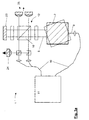
- the measuring method shown is an example of method V3 optical Fabry-Perot resonators with a laser interferometric measurement and Control arrangement according to the heterodyne method.
- the sample mass 2 designed as an example, is from a housing 3 surrounded on which a shield 4, e.g. ⁇ metal, is applied, whereby electromagnetic fields are shielded.
- a shield 4 e.g. ⁇ metal
- the resonators 7 serve on the one hand as optical measuring sections 8 and on the other hand as compensation paths 9 to compensate for that exerted on the sample mass 2 Light pressure.
- Piezo actuator or electro-optical elements 10 for tuning the resonators 7.
- the laser interferometric measurement and control system consists of one, for everyone optical lines common frequency-stabilized laser source 11, e.g. one Nd: YAG laser (e.g. with a power of less than 100 mW), an interferometer lens 12, a frequency reference 13 for frequency stabilization of the laser source and a detector 14.
- a detector 15 is connected downstream of the detector 14 Control of the laser frequency and the piezo actuator 10. Furthermore, the piezo actuator 10 can be controlled independently of the detector 14 by the laser source 11.
- the laser light from the laser source 11 is via a single-mode, polarization-maintaining Optical fiber cable 16 is routed to the interferometer optics 12, where it is in a polarization beam splitter 17 is divided into two partial beams.
- One beam 18 is the Detector 14 supplied, the other sub-beam 19 enters the resonator 7 between the Reference elements 5 and 6.
- the resonators 7 As described, form within the resonators 7 depending on the Resonator length, which is adjustable via the piezo actuator 10, and the laser frequency longitudinal and transverse resonator modes.
- a small part of the the resonators 7 stored laser power is by the housing side Reference elements 5, e.g. semi-transparent mirror, coupled out of the resonators 7.
- This decoupled laser beam is in the interferometer optics 12 with the Partial beam 18 is superimposed and generates an interference pattern that is applied to the detector 14 is imaged and detected.
- a Fabry-Perot resonator 7 As described, self-regulating positioning of the sample mass 2 can be achieved.
- a change in the laser frequency, a resonator coordination with the piezo actuators 10 or by a relative displacement of the sample mass 2 induces a positional disturbance ⁇ L of the sample mass 2 in the resonators 7.
- a targeted excitation of the resonator modes by using the resonance increase leads to an increase in the light pressure by a factor of 1000.
- a restoring force is exerted on the sample mass 2 in the optical sections 8 and 9, which results in a self-centering of the sample mass 2 in the housing 3.
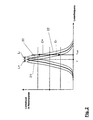
- Fig. 2 shows the principle of the light pressure-induced position and position.
- Reference numeral 20 designates the resonator mode with the solid curve a resonance frequency v, which is at a nominal resonator length L in the optical Forms measuring section 8 and the corresponding compensation section 9.
- the dotted curves 21 and 22 show that in the event of a positional error ⁇ L Test mass 2 forming resonator modes.
- Reference numeral 21 denotes here the resonator mode in the optical measuring path 8 and reference numeral 22 den Resonator mode in the corresponding compensation path 9.
- a change in the resonator lengths in the optical links 8 and 9 results from the positional disturbance ⁇ L.
- ⁇ is intended by operation of the laser frequency on the higher-frequency flank of a longitudinal resonator, the differential pressure of light in the optical paths 8 and 9 is controlled.
- the light pressures on the sample mass 2 in the optical sections 8 and 9 compensate for the target position and generate suitable restoring forces in the event of longitudinal position disturbances.
- a desired acceleration of the sample mass can be achieved by tuning the laser frequency, in particular also by operating on the low-frequency flank.
- FIG 3a shows an alternative device of an inertial sensor 1 according to the invention according to configuration A1 for carrying out position and position measurement by means of laser heterodyne interferometry (V1).
- V1 laser heterodyne interferometry
- the device according to the invention consists of a Sample mass 2, a laser source 11, e.g. Nd: YAG laser, per degree of freedom from one Interferometer optics 12 with a downstream optical heterodyne interferometric Measuring section 8 and an associated compensation section 9.
- the laser light is, as described in FIG. 1, by single-mode, polarization-maintaining Fiber optic cable 16 passed.
- the interferometer optics 12 are similar to the construction of a conventional Michelson interferometer with a polarization beam splitter 17, a fixed reference mirror 23 as well as the sample mass 2 as a mirror variable in position and position.
- the On the one hand, interferometer optics 11 have a reference detector 24 connected upstream and on Heterodyne detector 25 downstream.
- the Position of sample mass 2 and secondly the tilting of the sample mass certainly.
- the light pressure exerted on the sample mass 2 by the partial beams is compensated by the laser beam in the compensation section 9.
- the controllable Position angle range is due to the adjustment requirements of the laser interferometer limited.
- 3b shows an example of a sample mass 2 in the form of a cube 3 optical measuring sections 8 for determining the position and location of the sample mass.
- the test mass can be on a slowly rotating platform 26 and rotate with it.
- FIG. 4 shows in a further advantageous application (embodiment A2) of the Inertial sensor 1 according to the invention, which is operated as a common and continuously operated Position reference can be used for several satellites or parts of satellites can. Between the satellites or satellite parts not shown outside the Housing and sample mass 2 are additional laser interferometric measuring sections 27 available.
- the angle ⁇ between the individual laser interferometric measuring sections 27 can be variable over time.
- the distance of the satellites can be determined by means of the optical measuring paths 27 within a satellite constellation, which is typically several million kilometerss is determined.
- the sample mass 2 is located within a housing 3 and can be one rotate any axis or rest inertially.
- the housing 3 has for the laser interferometric Measuring sections 27 additional openings.
- the trial mass 2 and the housing 3 are advantageously spherical. It is also one Design of the sample mass 2 is conceivable, in which only the reference surfaces of the optical measuring sections 27 are spherical on the sample mass 2.
- measuring sections 8 which are also called compensation sections can serve, the degrees of freedom of the sample mass 2 as described independently controlled and controlled.
- the measurement sections 8 are advantageous at a fixed angle e.g. tetrahedral to sample mass 2 arranged.
- optical measuring paths 27 and 8 are advantageously on the center of the Sample mass 2 aligned, the alignment of the optical measuring section 8 the optical center of the sample mass 2, as described, by measuring the Excitation of the resonator modes is controlled.
Landscapes
- Engineering & Computer Science (AREA)
- Remote Sensing (AREA)
- Chemical & Material Sciences (AREA)
- Combustion & Propulsion (AREA)
- Radar, Positioning & Navigation (AREA)
- Aviation & Aerospace Engineering (AREA)
- Physics & Mathematics (AREA)
- General Physics & Mathematics (AREA)
- Length Measuring Devices By Optical Means (AREA)
- Lasers (AREA)
- Gyroscopes (AREA)
Abstract
Description
- eine minimale magnetische Suszeptibilität,
- eine hohe thermische und elektrische Leitfähigkeit,
- eine hohe Dichte und
- ein geringer thermischer Ausdehungskoeffizient.
- die Heterodyninterferometrie im folgenden auch mit V1 bezeichnet,
- die klassische Interferometrie mit einem Michelsoninterferometer (V2) und
- der Einsatz eines optischen Resonators (Fabry-Perot) mit einer Überwachung der Resonatormoden mittels Heterodynverfahren (V3).
- die Eliminierung der Störeinflüsse elektrischer Felder, wodurch eine bessere Entkopplung vom Satellitenkörper ermöglicht wird,
- eine hohe Auflösung bis in den Pikometer-Bereich,
- eine ausgedehnten linearen Kennlinie um den Arbeitspunkt,
- die Bestimmung von Lage und Position der Probemasse in bis zu 6 Freiheitsgraden,
- dass der Abstand zwischen Probemasse und Gehäuse (Referenzelementen) in einem weiten Bereich (µm bis m) gewählt werden kann.
- A1:
- erfindungsgemäßer Inertialsensor als Positions- und Rotationsreferenz für einen inertial ruhenden oder langsam rotierenden Satelliten.
- A2:
- erfindungsgemäßer Inertialsensor als gemeinsame Positionsreferenz zweier oder mehrerer, unter variablen Winkel sich befindlicher optischer interferometrischer Messstrecken.
- Fig. 1 :
- eine erfindungsgemäße Vorrichtung nach Ausführung A1 für die Durchführung eines Messverfahrens nach V3.
- Fig. 2 :
- das Prinzip der Position- und Lageregelung mittels Lichtdruck nach Messverfahren V3.
- Fig. 3a:
- eine erfindungsgemäße Vorrichtung nach Ausführung A1 für die Durchführung eines Messverfahrens nach V1.
- Fig. 3b :
- die auf die Probemasse ausgerichteten optischen Messstrecken gemäß Fig. 3a.
- Fig. 4 :
- eine erfindungsgemäße Vorrichtung nach Ausführung A2 für die Durchführung eines Messverfahrens nach V3.
Eine gezielte Anregung der Resonatormoden unter Ausnutzung der Resonanzüberhöhung führt zu einer Steigerung des Lichtdrucks um den Faktor 1000. Somit wird in den optischen Strecken 8 und 9 eine Rückstellkraft auf die Probemasse 2 ausgeübt, wodurch sich eine Selbstzentrierung der Probemasse 2 im Gehäuse 3 ergibt. Fig. 2 zeigt das Prinzip der lichtdruckinduzierten Position- und Lagestellung.
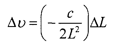
Durch geeignete Wahl und Fixierung der Laserfrequenz kompensieren sich die Lichtdrucke auf die Probemasse 2 in den optischen Strecken 8 und 9 bei der Sollposition und erzeugen geeignete Rückstellkräfte bei longitudinalen Positionsstörungen. Umgekehrt kann durch Abstimmung der Laserfrequenz, insbesondere auch durch Betrieb auf der niederfrequenten Flanke eine gewünschte Beschleunigung der Probemasse erreicht werden.
- 1
- Inertialsensor
- 2
- Probemasse
- 3
- Gehäuse
- 4
- Abschirmung auf dem Gehäuse angebracht
- 5
- Referenzelement am Gehäuse
- 6
- Referenzelement an Probemasse
- 7
- Resonator
- 8
- optische Messstrecke
- 9
- optische Kompensationsstrecke
- 10
- Piezosteller
- 11
- Laserquelle
- 12
- Interferometeroptik
- 13
- Frequenzreferenz
- 14
- Detektor
- 15
- Kontroller
- 16
- Glasfaserkabel
- 17
- Polarisationsstrahlteiler
- 18
- Teilstrahl
- 19
- Teilstrahl
- 20
- Resonatormode bei Resonanzfrequenz
- 21
- Resonatormode in optischer Messstrecke 7
- 22
- Resonatormode in optischer Kompensationsstrecke 8
- 23
- Referenzspiegel
- 24
- Referenzdetektor
- 25
- Heterodyndetektor
- 26
- Plattform
- 27
- laserinterferometrische Messstrecken
- D+
- Erhöhung des differentiellen Lichtdrucks
- D-
- Erniedrigung des differentiellen Lichtdrucks
- L+
- Verlängerung der optischen Strecke
- L-
- Verkürzung der optischen Strecke
- ν
- Resonanzfrequenz
- νsoll
- Soll-Laserfrequenz
- α
- variabler Winkel
Claims (24)
- Inertialsensor (1) als Inertialreferenz zur Lage- und Positionsbestimmung von Satelliten oder Satellitenteilen, umfassenddadurch gekennzeichnet, dass die optische Messstrecken (8, 9) als optische interferometrische Messstrecken ausgeführt sind, und dass mittels der in den optischen interferometrischen Messstrecken (8, 9) auf die Probemasse (2) ausgeübten Lichtdrucke die Lage und Position der Probemasse (2) einstellbar ist.eine Probemasse (2), die sich in einem elektrisch und magnetisch im wesentlichen feldfreiem, von einem Gehäuse (3, 4) umschlossenen Raum befindet,zwischen Referenzelementen (5, 6) am Gehäuse (3) und an der Probemasse (2) eingerichtete optische Messstrecken (8, 9) zur Bestimmung von Lage und/oder Position der Probemasse (2) relativ zu den Referenzelementen (5) am Gehäuse (3),eine sich außerhalb des Gehäuses (3, 4) befindliche Meßanordnung (11, 12, 13, 14, 15) für die optischen Messstrecken (8, 9),
- Inertialsensor nach Anspruch 1, dadurch gekennzeichnet, dass die Probemasse (2) inertial frei schwebt.
- Inertialsensor nach Anspruch 1, dadurch gekennzeichnet, dass die Probemasse (2) mit dem Gehäuse (3) um eine gemeinsame Achse mit gleicher nominaler Winkelgeschwindigkeit rotiert.
- Inertialsensor nach einem der vorangehenden Ansprüche, dadurch gekennzeichnet, dass das Gehäuse (3) im wesentlichen ein schwarzer Körper ist.
- Inertialsensor nach einem der vorangehenden Ansprüche, dadurch gekennzeichnet, dass der Abstand zwischen Probemasse (2) und Gehäuse (3) bis zu einigen Meter betragen kann.
- Inertialsensor nach einem der vorangehenden Ansprüche, dadurch gekennzeichnet, dass die Oberfläche der Probemasse (2) als Reflektor ausgebildet ist oder dass auf der Oberfläche der Probemasse (2) im Bereich der Referenzelemente (5) sphärische zentrierte optische Reflektorelemente, z.B., Spiegel, aufgebracht sind.
- Inertialsensor nach Anspruch 6, dadurch gekennzeichnet, dass die Oberfläche der Probemasse (2) oder die optischen Reflektorelemente einen Endspiegel einer der optischen interferometrischen Messstrecken (8, 9) bilden.
- Inertialsensor nach einem der vorangehenden Ansprüche, dadurch gekennzeichnet, dass die optischen interferometrischen Messstrecken (8, 9) derart zueinander angeordnet sind, dass die in den einzelnen Messstrecken (8, 9) auf die Probemasse (2) ausgeübten Lichtdrucke gegenseitig kompensiert werden.
- Inertialsensor nach Anspruch 8, dadurch gekennzeichnet, dass die optischen Achsen der optischen interferometrischen Messstrecken (8, 9) auf das Massezentrum und das geometrische Zentrum der Probemasse (2) ausgerichtet sind.
- Inertialsensor nach einem der vorangehenden Ansprüche, dadurch gekennzeichnet, dass durch Variation des Lichtdrucks in den optischen interferometrischen Messstrecken (8, 9) Position und/oder Lage der Probemasse (2) einstellbar ist.
- Inertialsensor nach einem der vorangehenden Ansprüche, dadurch gekennzeichnet, dass die optischen interferometrischen Messstrecken (8, 9) ein Zweig eines Heterodyninterferometers sind.
- Inertialsensor nach Anspruch 1 bis 10, dadurch gekennzeichnet, dass die optischen Messstrecken (8, 9) ein Zweig einer Michelsoninterferometeranordnung sind.
- Inertialsensor nach Anspruch 1 bis 10, dadurch gekennzeichnet, dass die optischen Messstrecken (8, 9) passive optische Resonatoren (7) sind.
- Inertialsensor nach Anspruch 13, dadurch gekennzeichnet, dass in den optischen Resonatoren (7) longitudinale und transversale Resonatormoden einstellbar sind und dass mit deren Messung Position und/oder Lage der Probemasse (2) bestimmbar sind.
- Inertialsensor nach Anspruch 14, dadurch gekennzeichnet, dass der Lichtdruck in den einzelnen Moden durch Resonatorabstimmung mittels der in den optischen Messstrecken (8, 9) angeordneten Piezo (10) oder elektro-optische Elemente variiert werden kann.
- Inertialsensor nach Anspruch 14, dadurch gekennzeichnet, dass der Lichtdruck in den einzelnen Moden durch Variation der Laserfrequenz verändert werden kann.
- Inertialsensor nach Anspruch 14, dadurch gekennzeichnet, dass der Lichtdruck in den einzelnen Moden durch eine gezielte Anregung der longitudinalen und transversalen Resonatormoden unter Ausnutzung der Resonanzüberhöhung verändert werden kann.
- Inertialsensor nach Anspruch 14, dadurch gekennzeichnet, dass der Lichtdruck in den einzelnen Moden durch eine relative Verschiebung oder Verkippung der Probemasse (2) verändert werden kann.
- Inertialsensor nach einem der vorangehenden Ansprüche 13 bis 18, dadurch gekennzeichnet, dass die optischen interferometrischen Messstrecken (8, 9) derart verschaltet sind, dass sich innerhalb der optischen Messstrecken (8, 9) eine Selbstzentrierung der Probemasse (2) aufgrund der Variation des Lichtdrucks ergibt.
- Inertialsensor nach Anspruch 19, dadurch gekennzeichnet, dass sich die Selbstzentrierung durch Betrieb der Laserfrequenz auf der höherfrequenten Flanke eines longitudinalen Resonatormodes ergibt.
- Inertialsensor nach einem der vorangehenden Ansprüche, dadurch gekennzeichnet, dass Position und/oder Lage der Probemasse (2) in bis zu 6 Freiheitsgraden bestimmbar sind.
- Inertialsensor nach einem der vorangehenden Ansprüche, dadurch gekennzeichnet, dass mindestens zwei weitere optische Messstrecken (27) zwischen der Probemasse (2) und je einem Punkt außerhalb des Gehäuses (3, 4) eingerichtet sind und dass diese optischen Messstrecken (27) dabei auf das optische Zentrum sowie Massezentrum der Probemasse (2) ausgerichtet sind.
- Inertialsensor nach Anspruch 22, dadurch gekennzeichnet, dass der Winkel (α) zwischen den optischen Messstrecken (27) variierbar ist.
- Inertialsensor nach einem der vorangehenden Ansprüche, dadurch gekennzeichnet, dass die Probemasse (2) ganz oder teilweise kugelförmig ist.
Applications Claiming Priority (2)
| Application Number | Priority Date | Filing Date | Title |
|---|---|---|---|
| DE10031542A DE10031542B4 (de) | 2000-06-28 | 2000-06-28 | Inertialsensor zur Lagerung und Kontrolle einer Inertialreferenz in einem Satelliten |
| DE10031542 | 2000-06-28 |
Publications (2)
| Publication Number | Publication Date |
|---|---|
| EP1167978A1 true EP1167978A1 (de) | 2002-01-02 |
| EP1167978B1 EP1167978B1 (de) | 2009-04-08 |
Family
ID=7647119
Family Applications (1)
| Application Number | Title | Priority Date | Filing Date |
|---|---|---|---|
| EP01112524A Expired - Lifetime EP1167978B1 (de) | 2000-06-28 | 2001-05-23 | Inertialsensor zur Lagerung und Kontrolle einer Inertialreferenz in einem Satelliten |
Country Status (3)
| Country | Link |
|---|---|
| US (1) | US6606908B2 (de) |
| EP (1) | EP1167978B1 (de) |
| DE (2) | DE10031542B4 (de) |
Families Citing this family (10)
| Publication number | Priority date | Publication date | Assignee | Title |
|---|---|---|---|---|
| DE10327525A1 (de) * | 2003-06-17 | 2005-01-13 | Siemens Ag | Befestigungseinrichtung |
| US7451645B2 (en) * | 2004-12-22 | 2008-11-18 | Micro-G Lacoste, Inc. | Test mass for gravimeters and gradiometers |
| DE102007052409B3 (de) * | 2007-10-31 | 2009-04-23 | Astrium Gmbh | Verfahren und Vorrichtung zum Entladen einer frei in einem Satelliten fliegenden Testmasse |
| US9030655B2 (en) | 2012-06-27 | 2015-05-12 | Honeywell International Inc. | Closed loop atomic inertial sensor |
| US8860933B2 (en) | 2012-07-12 | 2014-10-14 | Honeywell International Inc. | Multi-axis atomic inertial sensor system |
| RU2524687C2 (ru) * | 2012-11-06 | 2014-08-10 | Открытое акционерное общество "Информационные спутниковые системы" имени академика М.Ф. Решетнёва" | Космический измеритель приращения скорости |
| WO2015012094A1 (ja) * | 2013-07-25 | 2015-01-29 | 白山工業株式会社 | 光干渉式センサ及びそれを用いた計測システム |
| FR3032801B1 (fr) * | 2015-02-17 | 2017-02-24 | Commissariat Energie Atomique | Dispositif de mesure d'un champ electrique en milieu conducteur |
| CN110907956B (zh) * | 2019-12-06 | 2023-03-24 | 中国空空导弹研究院 | 一种飞行器载抗干扰卫星定位组件试验系统 |
| CN114966105B (zh) * | 2022-04-18 | 2023-07-14 | 北京华卓精科科技股份有限公司 | 一种加速度计 |
Citations (3)
| Publication number | Priority date | Publication date | Assignee | Title |
|---|---|---|---|---|
| US3275835A (en) * | 1964-01-27 | 1966-09-27 | Honeywell Inc | Photosensitive accelerometer utilizing radiation pressure |
| US3710279A (en) * | 1969-12-15 | 1973-01-09 | Bell Telephone Labor Inc | Apparatuses for trapping and accelerating neutral particles |
| DE3606875A1 (de) * | 1986-03-03 | 1987-09-10 | Messerschmitt Boelkow Blohm | Optoelektronischer beschleunigungsmesser |
Family Cites Families (9)
| Publication number | Priority date | Publication date | Assignee | Title |
|---|---|---|---|---|
| US4384487A (en) * | 1974-09-30 | 1983-05-24 | Browning Alva L | Dynamically restrained inertial reference instrument and reliability sensor |
| US4170904A (en) * | 1977-12-12 | 1979-10-16 | The United States Of America As Represented By The Secretary Of The Navy | Single-axis disturbance compensation system |
| US4799752A (en) * | 1987-09-21 | 1989-01-24 | Litton Systems, Inc. | Fiber optic gradient hydrophone and method of using same |
| JPH0274499A (ja) * | 1988-09-08 | 1990-03-14 | Toshiba Corp | 宇宙航行体 |
| GB8902034D0 (en) * | 1989-01-31 | 1989-03-22 | Kent Scient Ind Projects | Optical displacement sensor |
| CA2096069C (en) * | 1992-05-14 | 1998-09-01 | Shuichi Kawasaki | Vibration detection and reduction system and vibration sensors for use in micro-gravity environment |
| US5546309A (en) * | 1993-10-20 | 1996-08-13 | The Charles Stark Draper Laboratory, Inc. | Apparatus and method for autonomous satellite attitude sensing |
| US6018390A (en) * | 1998-01-27 | 2000-01-25 | Rice Systems, Inc. | Integrated optics waveguide accelerometer with a proof mass adapted to exert force against the optical waveguide during acceleration |
| DE19921390B4 (de) * | 1999-05-10 | 2005-06-09 | Eads Astrium Gmbh | Positionierungssystem für eine Meßeinrichtung eines Satelliten |
-
2000
- 2000-06-28 DE DE10031542A patent/DE10031542B4/de not_active Expired - Fee Related
-
2001
- 2001-05-23 DE DE50114815T patent/DE50114815D1/de not_active Expired - Fee Related
- 2001-05-23 EP EP01112524A patent/EP1167978B1/de not_active Expired - Lifetime
- 2001-06-28 US US09/892,782 patent/US6606908B2/en not_active Expired - Fee Related
Patent Citations (3)
| Publication number | Priority date | Publication date | Assignee | Title |
|---|---|---|---|---|
| US3275835A (en) * | 1964-01-27 | 1966-09-27 | Honeywell Inc | Photosensitive accelerometer utilizing radiation pressure |
| US3710279A (en) * | 1969-12-15 | 1973-01-09 | Bell Telephone Labor Inc | Apparatuses for trapping and accelerating neutral particles |
| DE3606875A1 (de) * | 1986-03-03 | 1987-09-10 | Messerschmitt Boelkow Blohm | Optoelektronischer beschleunigungsmesser |
Also Published As
| Publication number | Publication date |
|---|---|
| US20020036251A1 (en) | 2002-03-28 |
| DE10031542A1 (de) | 2002-01-17 |
| US6606908B2 (en) | 2003-08-19 |
| DE10031542B4 (de) | 2005-02-17 |
| DE50114815D1 (de) | 2009-05-20 |
| EP1167978B1 (de) | 2009-04-08 |
Similar Documents
| Publication | Publication Date | Title |
|---|---|---|
| Hignette et al. | Incoherent X-ray mirror surface metrology | |
| EP1167978B1 (de) | Inertialsensor zur Lagerung und Kontrolle einer Inertialreferenz in einem Satelliten | |
| EP3224570B1 (de) | Verfahren und vorrichtung zur interferometrischen prüfung | |
| DE2839066A1 (de) | Ringlaser-kreisel | |
| DE3606875C2 (de) | ||
| DE102023209192A1 (de) | Messanordnung zur Positionsbestimmung einer bewegbaren Komponente, optisches System, insbesondere mikrolithographische Projektionsbelichtungsanlage | |
| CN111043973A (zh) | 一种氢同位素结晶高度及表面粗糙度干涉测量装置及方法 | |
| Haddad et al. | First measurements of the flux integral with the NIST-4 watt balance | |
| DE19816914B4 (de) | Abtastmikroskop | |
| Qian et al. | In situ surface profiler for high heat load mirror measurement | |
| Bertolini | High sensitivity accelerometers for gravity experiments | |
| Keck | Flexure-based mechanism for a Kibble Balance | |
| EP3628964B1 (de) | Opto-elektro-mechanisches strahlmanipulationssystem | |
| DE102014209379A1 (de) | Laser-Tracking-Interferometer | |
| Wang et al. | Performance evaluation of optical-beam stabilization platforms with different supports used in large-aperture electro-optical system | |
| JP3704952B2 (ja) | 媒質の測定装置および測定方法 | |
| Bauer | Probe-based nano-interferometric reconstruction of tightly focused vectorial light fields | |
| Halbgewachs et al. | Building large Fabry-Pérot etalons for the Visible Tunable Filter | |
| Berta et al. | Development of a commercial line of high-performance fast-steering mirrors | |
| Mandel | Optical metrology terminal for satellite-to-satellite laser ranging | |
| Sha et al. | Successful application of optical bench in Taiji-1 laser interferometer | |
| Smith et al. | A simple two‐axis ultraprecision actuator | |
| Hignette et al. | Status of the optical metrology at the ESRF | |
| Hashimoto et al. | Concept of MEMS ring laser gyroscope with movable optical parts | |
| DE102018218488A1 (de) | Messanordnung zur interferometrischen Absolutmessung des Abstandes zwischen zwei Komponenten in einem optischen System für die Mikrolithographie |
Legal Events
| Date | Code | Title | Description |
|---|---|---|---|
| PUAI | Public reference made under article 153(3) epc to a published international application that has entered the european phase |
Free format text: ORIGINAL CODE: 0009012 |
|
| AK | Designated contracting states |
Kind code of ref document: A1 Designated state(s): AT BE CH CY DE DK ES FI FR GB GR IE IT LI LU MC NL PT SE TR Kind code of ref document: A1 Designated state(s): DE FR GB IT |
|
| AX | Request for extension of the european patent |
Free format text: AL;LT;LV;MK;RO;SI |
|
| 17P | Request for examination filed |
Effective date: 20020328 |
|
| AKX | Designation fees paid |
Free format text: DE FR GB IT |
|
| RAP1 | Party data changed (applicant data changed or rights of an application transferred) |
Owner name: EADS ASTRIUM GMBH |
|
| 17Q | First examination report despatched |
Effective date: 20080509 |
|
| GRAP | Despatch of communication of intention to grant a patent |
Free format text: ORIGINAL CODE: EPIDOSNIGR1 |
|
| GRAS | Grant fee paid |
Free format text: ORIGINAL CODE: EPIDOSNIGR3 |
|
| GRAA | (expected) grant |
Free format text: ORIGINAL CODE: 0009210 |
|
| RAP1 | Party data changed (applicant data changed or rights of an application transferred) |
Owner name: ASTRIUM GMBH |
|
| AK | Designated contracting states |
Kind code of ref document: B1 Designated state(s): DE FR GB IT |
|
| REG | Reference to a national code |
Ref country code: GB Ref legal event code: FG4D Free format text: NOT ENGLISH |
|
| REF | Corresponds to: |
Ref document number: 50114815 Country of ref document: DE Date of ref document: 20090520 Kind code of ref document: P |
|
| PGFP | Annual fee paid to national office [announced via postgrant information from national office to epo] |
Ref country code: IT Payment date: 20090523 Year of fee payment: 9 Ref country code: FR Payment date: 20090513 Year of fee payment: 9 Ref country code: DE Payment date: 20090525 Year of fee payment: 9 |
|
| PGFP | Annual fee paid to national office [announced via postgrant information from national office to epo] |
Ref country code: GB Payment date: 20090522 Year of fee payment: 9 |
|
| PLBE | No opposition filed within time limit |
Free format text: ORIGINAL CODE: 0009261 |
|
| STAA | Information on the status of an ep patent application or granted ep patent |
Free format text: STATUS: NO OPPOSITION FILED WITHIN TIME LIMIT |
|
| 26N | No opposition filed |
Effective date: 20100111 |
|
| GBPC | Gb: european patent ceased through non-payment of renewal fee |
Effective date: 20100523 |
|
| REG | Reference to a national code |
Ref country code: FR Ref legal event code: ST Effective date: 20110131 |
|
| PG25 | Lapsed in a contracting state [announced via postgrant information from national office to epo] |
Ref country code: IT Free format text: LAPSE BECAUSE OF NON-PAYMENT OF DUE FEES Effective date: 20100523 |
|
| PG25 | Lapsed in a contracting state [announced via postgrant information from national office to epo] |
Ref country code: DE Free format text: LAPSE BECAUSE OF NON-PAYMENT OF DUE FEES Effective date: 20101201 |
|
| PG25 | Lapsed in a contracting state [announced via postgrant information from national office to epo] |
Ref country code: FR Free format text: LAPSE BECAUSE OF NON-PAYMENT OF DUE FEES Effective date: 20100531 |
|
| PG25 | Lapsed in a contracting state [announced via postgrant information from national office to epo] |
Ref country code: GB Free format text: LAPSE BECAUSE OF NON-PAYMENT OF DUE FEES Effective date: 20100523 |