EP1167858B1 - Coude de tuyau pour le transport de matières abrasives - Google Patents
Coude de tuyau pour le transport de matières abrasives Download PDFInfo
- Publication number
- EP1167858B1 EP1167858B1 EP01110710A EP01110710A EP1167858B1 EP 1167858 B1 EP1167858 B1 EP 1167858B1 EP 01110710 A EP01110710 A EP 01110710A EP 01110710 A EP01110710 A EP 01110710A EP 1167858 B1 EP1167858 B1 EP 1167858B1
- Authority
- EP
- European Patent Office
- Prior art keywords
- bend
- jacket
- pipe
- rings
- pipe bend
- Prior art date
- Legal status (The legal status is an assumption and is not a legal conclusion. Google has not performed a legal analysis and makes no representation as to the accuracy of the status listed.)
- Expired - Lifetime
Links
Images


Classifications
-
- F—MECHANICAL ENGINEERING; LIGHTING; HEATING; WEAPONS; BLASTING
- F16—ENGINEERING ELEMENTS AND UNITS; GENERAL MEASURES FOR PRODUCING AND MAINTAINING EFFECTIVE FUNCTIONING OF MACHINES OR INSTALLATIONS; THERMAL INSULATION IN GENERAL
- F16L—PIPES; JOINTS OR FITTINGS FOR PIPES; SUPPORTS FOR PIPES, CABLES OR PROTECTIVE TUBING; MEANS FOR THERMAL INSULATION IN GENERAL
- F16L57/00—Protection of pipes or objects of similar shape against external or internal damage or wear
-
- B—PERFORMING OPERATIONS; TRANSPORTING
- B65—CONVEYING; PACKING; STORING; HANDLING THIN OR FILAMENTARY MATERIAL
- B65G—TRANSPORT OR STORAGE DEVICES, e.g. CONVEYORS FOR LOADING OR TIPPING, SHOP CONVEYOR SYSTEMS OR PNEUMATIC TUBE CONVEYORS
- B65G53/00—Conveying materials in bulk through troughs, pipes or tubes by floating the materials or by flow of gas, liquid or foam
- B65G53/32—Conveying concrete, e.g. for distributing same at building sites
-
- B—PERFORMING OPERATIONS; TRANSPORTING
- B65—CONVEYING; PACKING; STORING; HANDLING THIN OR FILAMENTARY MATERIAL
- B65G—TRANSPORT OR STORAGE DEVICES, e.g. CONVEYORS FOR LOADING OR TIPPING, SHOP CONVEYOR SYSTEMS OR PNEUMATIC TUBE CONVEYORS
- B65G53/00—Conveying materials in bulk through troughs, pipes or tubes by floating the materials or by flow of gas, liquid or foam
- B65G53/34—Details
- B65G53/52—Adaptations of pipes or tubes
- B65G53/523—Wear protection
-
- F—MECHANICAL ENGINEERING; LIGHTING; HEATING; WEAPONS; BLASTING
- F16—ENGINEERING ELEMENTS AND UNITS; GENERAL MEASURES FOR PRODUCING AND MAINTAINING EFFECTIVE FUNCTIONING OF MACHINES OR INSTALLATIONS; THERMAL INSULATION IN GENERAL
- F16L—PIPES; JOINTS OR FITTINGS FOR PIPES; SUPPORTS FOR PIPES, CABLES OR PROTECTIVE TUBING; MEANS FOR THERMAL INSULATION IN GENERAL
- F16L43/00—Bends; Siphons
- F16L43/001—Bends; Siphons made of metal
-
- F—MECHANICAL ENGINEERING; LIGHTING; HEATING; WEAPONS; BLASTING
- F16—ENGINEERING ELEMENTS AND UNITS; GENERAL MEASURES FOR PRODUCING AND MAINTAINING EFFECTIVE FUNCTIONING OF MACHINES OR INSTALLATIONS; THERMAL INSULATION IN GENERAL
- F16L—PIPES; JOINTS OR FITTINGS FOR PIPES; SUPPORTS FOR PIPES, CABLES OR PROTECTIVE TUBING; MEANS FOR THERMAL INSULATION IN GENERAL
- F16L57/00—Protection of pipes or objects of similar shape against external or internal damage or wear
- F16L57/06—Protection of pipes or objects of similar shape against external or internal damage or wear against wear
Definitions
- the invention relates to a pipe bend as part of a pipe string for Transport of abrasive materials according to the characteristics in the preamble of the Claim 1.
- Pipe shots have high requirements.
- the pipe sections are supposed to and here in particular those in the tubing with different curvatures integrated pipe bends with a high internal surface Ensure wear resistance.
- Pipe sections to the environment should be designed from the material so that they can withstand impact and impact loads without cracking. With in other words, the pipe sections should be hard inside and outside be soft.
- one pipe string is sufficient, e.g. the DE 198 09 529 A1 designed the pipe sections in two layers.
- the inner layers have been hardened at least over a substantial part of their radial thickness, while the outer layers are made of weldable steel. This also takes into account the fact that the outer locations were connected at the end with coupling collars that connect two successive pipe sections served in a pipe string.
- This Coupling collars were designed so that their end faces were at right angles to the longitudinal axes, so that when one individual wears Pipe shot of this after removing the corresponding one, as a rule two-piece, coupling clamps for themselves radially removed from the tubing and could be replaced by a new pipe shot, without that for such Exchange of the pipe string had to be pulled apart axially.
- the end coupling collars of such pipe elbows exist for one State of the art design each consisting of an outer ring with a circumferential outer coupling groove and one arranged in the outer ring Inner ring made of a more wear resistant compared to the material of the outer ring Material.
- the inner rings are only on the end faces the pipe bends secured against axial displacement. Because the inner Components of the pipe bends in question, i.e. the inner rings and the Inner layers, due to the unavoidable manufacturing tolerances relative play can be assigned to each other by the pressure of the transporting materials that are in the flow direction at the back Inner rings together with the inner layers towards the flow direction front inner rings are moved.
- the area of the pipe bend is between the coupling flanges clamped inner shell segment semicircular cross section in radial distance from the casing tube is provided, the leg end faces extend in the median longitudinal plane.
- the wall thickness of the inner shell segment is less than that of the outer shell segment.
- the object of the invention is based on the prior art based on a pipe bend as part of a pipe string for transport of abrasive materials, e.g. Sand or concrete to create the requirements for high wear resistance and easy interchangeability even better with simple production.
- abrasive materials e.g. Sand or concrete
- Such a pipe bend has between the two coupling collars at the ends one each with a circumferential outer coupling groove Outer ring and a more wear-resistant inner ring next to one of the jacket bows welded to the two outer rings compared to this consisting of a more wear-resistant material inner arc closed on the circumference.
- This inner arch is under radial Support on the jacket arch with formation of an annulus at both ends with regard to its inner cross section to the inner cross sections of the inner rings coaxially aligned.
- the annulus is made of a hardening plastic filled.
- an annular space that safely tolerates all manufacturing inaccuracies between the inner arch and the jacket arch is the inner arch through one over holes in the jacket bend in the annular space between the inner bend and quick-curing, pasty mass introduced into the jacket sheet radially fixed with respect to the mantle arch.
- This pasty mass is according to claim 2 especially a fast curing multi-component concrete Plastic base.
- the outer rings and the mantle arch consist of one weldable steel and the inner rings and the inner bow made of cast steel.
- a chromium carbide cast is preferably used as the cast steel. Since at Chromium carbide casting to avoid stress cracks and inner rings from This material is therefore very susceptible to breakage due to the exact axial clamping of the inner rings between the webs and the flanges ensures that even with a material such as chrome carbide casting, such Inner rings can fully perform their function.
- the resulting gap between the training according to the invention the inner bend, the inner rings and the outer bend are usually in operation of the pipe bend in the shortest possible time through the one to be transported Material filled in, so that the more wear-resistant inner arch so to speak, an additional cushion as a support against that of the Material her softer coat bow receives.
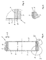
- FIG. 1 in Figures 1 to 3 is a pipe bend as part of an otherwise not illustrated pipe string for the transport of concrete designated.
- a pipe bend 1 can, for example, in a pipe string be used on construction sites to transport the concrete from a mobile or immobile concrete mixer in place of consumption serves.
- the pipe bend 1 has two end coupling collars 2 each an outer ring 3 made of weldable steel and an inner ring 4 Cast steel, in particular chrome carbide cast.
- the inner rings 4 are in the outer rings 3 axially fixed.
- each coupling collar 2 there is a front end 5 of each coupling collar 2 inward web 6 provided on the outer ring 3, which over extends part of the wall thickness WD of the inner rings 4.
- At the other Face 7 of each coupling collar 2 is made of the material of the outer ring 3 in some areas on the circumference, i.e. nose-like, or all over Scope 8 made a flare, which then against the adjacent End face 9 of the inner ring 4 abuts and presses it against the web 6, so that the inner rings 4 between the webs 6 and the flanges 8 clearly are fixed in both directions.
- the material deformation of the flanges 8 is interrupted in FIGS. 4 and 5 Lines illustrated.
- the axial length L is the Coupling collars 2 identical at both ends of the pipe bend 1 ( Figure 1). In this way, a radial removal of the pipe bend 1 is in the direction of the arrow PF from a pipe string and the subsequent reintegration a new pipe bend 1 in the opposite direction into the pipe string easily possible without pulling the pipe string apart should be.
- the outer rings 3 have circumferential outer coupling grooves 10 (figures 1 and 4). In these coupling grooves 10, the legs of not grasp illustrated cup-like coupling clamps.
- a jacket bow 11 made of weldable steel ( Figure 1).
- the wall thickness D of the jacket sheet 11 is smaller than the wall thickness D1 of the outer rings 3 sized.
- the ends 12 of the jacket sheet 11 are with V-seams 13 the outer rings 3 welded.
- the outer rings 3 and the jacket bend 11 configured accordingly at the ends (FIGS. 4 and 6).
- the inner bow 14 is both to the inner rings 4 and arranged to the jacket sheet 11 at a distance. This distance exceeds the manufacturing-related inaccuracies of all components of the elbow 1.
- the pipe bend 1 can be assembled using the manufacturing steps explained below respectively:
- FIG. 3 shows the embodiment according to the invention, in which the radial fixation of the Inner bow 14 to the jacket bow 11 through a through holes 22 in Sheath bow 11 in the annular space 21 between the inner bow 14 and the Sheath sheet 11 introduced quickly curing pasty mass 23, in particular in the form of fast-curing multi-component concrete Plastic base.
- the holes can 22 by, in particular steel, insert pins 24 are closed.
- the length of the insert pins 24 preferably corresponds to the wall thickness D of the Sheath bow 11.
- the insert pins 24 can be pressed into the bores 22 his. But it is also conceivable that the insert pins 24 with the Jacket elbows 11 are additionally welded. This can be done with a stitching on the outer surface 18 of the jacket sheet 11.
Landscapes
- Engineering & Computer Science (AREA)
- General Engineering & Computer Science (AREA)
- Mechanical Engineering (AREA)
- Civil Engineering (AREA)
- Structural Engineering (AREA)
- Rigid Pipes And Flexible Pipes (AREA)
- Polishing Bodies And Polishing Tools (AREA)
Claims (4)
- Coude tubulaire en tant que partie d'une suite de tubes pour le transport de matières abrasives, comme par exemple du sable ou du béton, qui, entre deux collets de couplage d'extrémité (2) constitués respectivement par une bague extérieure (3) possédant une gorge extérieure périphérique de couplage (10) et une bague intérieure (4) fixée axialement dans la bague extérieure (3) et réalisée en un matériau plus résistant à l'usure que le matériau de la bague extérieure (3), possède un coude enveloppe (11), qui est soudé aux deux bagues extérieures (3) et possède un diamètre intérieur qui est choisi supérieur au diamètre intérieur des bagues extérieures (3), caractérisé par la combinaison de caractéristiques suivantes:a) un coude intérieur (14) fermé circonférentiellement s'étend entre les deux bagues intérieures (4) à une certaine distance radiale du coude enveloppe (11);b) le coude intérieur (14) est réalisé entièrement en un matériau plus résistant à l'usure que le matériau du coude enveloppe (11);c) le coude intérieur (14) aligné coaxialement en ce qui concerne sa section transversale intérieure (19) aux deux extrémités sur les sections transversales intérieures (20) des bagues intérieures (4);d) l'espace annulaire (21) entre le coude intérieur (14) et le coude enveloppe (11) est rempli par une masse pâteuse qui durcit rapidement.
- Coude tubulaire selon la revendication 1, caractérisé en ce que la masse pâteuse est un béton à plusieurs constituants à base de matière plastique.
- Coude tubulaire selon la revendication 1 ou 2, caractérisé en ce que chaque bague intérieure (4) d'un collet de couplage (2) est serrée entre une barrette (6) dirigée vers l'intérieur, au niveau d'une extrémité frontale (5) de la bague extérieure associée (3), et un rebord (8) dirigé, au moins par endroits, radialement vers l'intérieur, sur l'autre extrémité frontale (7).
- Coude tubulaire selon l'une des revendications 1 à 3, caractérisé en ce que les bagues extérieures (3) ainsi que le coude enveloppe (11) sont réalisés en un acier soudable et les bagues intérieures (4) ainsi que le coude intérieur (14) sont réalisées en fonte.
Priority Applications (2)
| Application Number | Priority Date | Filing Date | Title |
|---|---|---|---|
| EP01110710A EP1167858B1 (fr) | 2000-07-01 | 2001-05-03 | Coude de tuyau pour le transport de matières abrasives |
| US09/884,865 US6494234B2 (en) | 2000-07-01 | 2001-06-19 | Pipe bend for a pipeline for transport of abrasive materials |
Applications Claiming Priority (5)
| Application Number | Priority Date | Filing Date | Title |
|---|---|---|---|
| DE10032074 | 2000-07-01 | ||
| DE10032074A DE10032074C1 (de) | 2000-07-01 | 2000-07-01 | Rohrbogen als Bestandteil eines Rohrstrangs zum Transport von abrasiven Materialien |
| EP00116455 | 2000-07-29 | ||
| EP00116455A EP1167857A3 (fr) | 2000-07-01 | 2000-07-29 | Coude de tuyau pour le transport de matières abrasives |
| EP01110710A EP1167858B1 (fr) | 2000-07-01 | 2001-05-03 | Coude de tuyau pour le transport de matières abrasives |
Publications (3)
| Publication Number | Publication Date |
|---|---|
| EP1167858A2 EP1167858A2 (fr) | 2002-01-02 |
| EP1167858A3 EP1167858A3 (fr) | 2003-06-04 |
| EP1167858B1 true EP1167858B1 (fr) | 2004-10-06 |
Family
ID=27213939
Family Applications (1)
| Application Number | Title | Priority Date | Filing Date |
|---|---|---|---|
| EP01110710A Expired - Lifetime EP1167858B1 (fr) | 2000-07-01 | 2001-05-03 | Coude de tuyau pour le transport de matières abrasives |
Country Status (2)
| Country | Link |
|---|---|
| US (1) | US6494234B2 (fr) |
| EP (1) | EP1167858B1 (fr) |
Cited By (1)
| Publication number | Priority date | Publication date | Assignee | Title |
|---|---|---|---|---|
| DE102005051766A1 (de) * | 2005-10-27 | 2007-05-03 | Esser-Werke Gmbh & Co. Kg | Rohrbogen und Verfahren zur Herstellung eines Rohrbogens |
Families Citing this family (19)
| Publication number | Priority date | Publication date | Assignee | Title |
|---|---|---|---|---|
| US6655459B2 (en) * | 2001-07-30 | 2003-12-02 | Weatherford/Lamb, Inc. | Completion apparatus and methods for use in wellbores |
| DE10143290B4 (de) * | 2001-09-04 | 2006-02-09 | Esser-Werke Kg | Bogenförmiges Doppellagenrohr |
| DE10149167A1 (de) * | 2001-10-04 | 2003-04-17 | Endress & Hauser Gmbh & Co Kg | Drei mit einer Schweißverbindung verbundene Bauteile |
| US7073612B2 (en) * | 2004-06-01 | 2006-07-11 | Finchum Ray A | Surge device for air drilling |
| EP1653138A1 (fr) * | 2004-10-28 | 2006-05-03 | Esser-Werke KG | Tuyau de transport pour matières solides |
| DE102006001315B3 (de) * | 2006-01-09 | 2007-05-24 | Esser-Werke Gmbh & Co. Kg | Rohrstrang zum hydraulischen oder pneumatischen Transport von Feststoffen |
| EP1873440B1 (fr) * | 2006-06-28 | 2009-01-14 | COMPAGNIA ITALIANA FORME ACCIAIO S.p.A. | Elément incurvé d'un tuyau modulaire en acier pour transport du béton ou des l'autres matériaux fortement abrasives à l'état du liquide, et procédé de fabrication d'un tel élément |
| DE102006038989B3 (de) * | 2006-08-21 | 2007-12-13 | Esser-Werke Gmbh & Co. Kg | Förderrohr für den Feststofftransport |
| US8282138B2 (en) * | 2008-12-18 | 2012-10-09 | Rostra Tool Company | Crimp ring |
| IT1401515B1 (it) * | 2010-08-03 | 2013-07-26 | Cifa S P A Unico Socio | Procedimento per realizzare un elemento tubolare curvo per il convogliamento di materiali abrasivi quali calcestruzzo, o simili, ed elemento tubolare curvo cosi' ottenuto. |
| US20130174935A1 (en) * | 2012-01-10 | 2013-07-11 | II Curtis R. Patterson | Variable thin walled duct with bend |
| CN105673979B (zh) * | 2015-03-12 | 2018-07-17 | 周朝辉 | 一种两分双层式耐磨抗冲击弯管及其制备方法 |
| ES2713407T3 (es) * | 2015-03-20 | 2019-05-21 | Valme S R L Unico Socio | Aparato y método para producir una tubería para transportar materiales abrasivos tales como hormigón |
| US10179661B2 (en) * | 2015-11-24 | 2019-01-15 | Hamilton Sundstrand Corporation | Ground connect duct for environmental control systems |
| EP3217060B1 (fr) * | 2016-03-11 | 2018-10-24 | Centrotherm Systemtechnik GmbH | Systeme de raccord coude double |
| US10436370B2 (en) * | 2016-04-20 | 2019-10-08 | Georg Fischer Central Plastics Llc | Pipe elbows and methods of manufacture |
| IT201800003964A1 (it) | 2018-03-26 | 2019-09-26 | Valme S R L Unico Socio | Elemento tubolare per il trasferimento di materiali abrasivi, in particolare calcestruzzo, e procedimento per realizzarlo |
| IT201800004795A1 (it) * | 2018-04-23 | 2019-10-23 | Elemento tubolare per il trasferimento di materiali abrasivi, in particolare calcestruzzo, e procedimento per realizzarlo | |
| US11485588B2 (en) * | 2020-03-20 | 2022-11-01 | Cnh Industrial America Llc | Wear resistant granular direction altering device |
Family Cites Families (14)
| Publication number | Priority date | Publication date | Assignee | Title |
|---|---|---|---|---|
| GB1336397A (en) * | 1971-06-25 | 1973-11-07 | Shaw Mcinnes Ltd | Structural elements and a method of producing s'me |
| DE3524757A1 (de) * | 1985-07-11 | 1987-01-22 | Stalter & Grosch Stahlhandel G | Foerderrohr |
| DE3821985C1 (fr) * | 1988-06-30 | 1990-03-01 | Metalpraecis Berchem + Schaberg Gesellschaft Fuer Metallformgebung Mbh, 4650 Gelsenkirchen, De | |
| DE4010556A1 (de) * | 1990-04-02 | 1991-10-10 | Esser Brieden Gmbh & Co Kg | Doppellagiger rohrbogen |
| US5379805A (en) * | 1992-12-16 | 1995-01-10 | Construction Forms | Single solid thin wall pipe for abrasive material having a gradual transition in hardness |
| DE19500952C1 (de) * | 1995-01-14 | 1996-07-25 | Esser Werke Gmbh & Co Kg | Rohrbogen |
| DE19500953C1 (de) * | 1995-01-14 | 1996-07-25 | Esser Werke Gmbh & Co Kg | Rohrbogen |
| DE29504332U1 (de) * | 1995-03-14 | 1995-05-11 | Esser Brieden Gmbh & Co Kg | Rohr zum Feststofftransport |
| JPH09152087A (ja) * | 1995-11-28 | 1997-06-10 | Naisu Kk | セラミックス製ライニング材及びそれを用いた輸送管のライニング方法 |
| NL1001961C2 (nl) * | 1995-12-21 | 1997-06-24 | Nederland Ptt | Werkwijze voor het installeren van een buizenstelsel met aftakkingen voor telecommunicatiekabels, alsmede een aftakelement voor toepassing bij die werkwijze. |
| DE19736055C1 (de) * | 1997-08-20 | 1998-06-04 | Esser Werke Gmbh & Co Kg | Rohrbogen |
| US6009908A (en) * | 1997-10-30 | 2000-01-04 | Chrysler Corporation | Tube assembly for auxiliary heating and air conditioning system |
| DE19809529C2 (de) * | 1998-03-05 | 2002-12-12 | Esser Werke Gmbh & Co Kg | Transportrohr |
| US6209319B1 (en) * | 1998-09-28 | 2001-04-03 | Honda Giken Kogyo Kabushiki Kaisha | Pipe assembly having inner and outer pipes |
-
2001
- 2001-05-03 EP EP01110710A patent/EP1167858B1/fr not_active Expired - Lifetime
- 2001-06-19 US US09/884,865 patent/US6494234B2/en not_active Expired - Fee Related
Cited By (2)
| Publication number | Priority date | Publication date | Assignee | Title |
|---|---|---|---|---|
| DE102005051766A1 (de) * | 2005-10-27 | 2007-05-03 | Esser-Werke Gmbh & Co. Kg | Rohrbogen und Verfahren zur Herstellung eines Rohrbogens |
| DE102005051766B4 (de) * | 2005-10-27 | 2009-02-26 | Esser-Werke Gmbh & Co. Kg | Rohrbogen und Verfahren zur Herstellung eines Rohrbogens |
Also Published As
| Publication number | Publication date |
|---|---|
| US20020005222A1 (en) | 2002-01-17 |
| US6494234B2 (en) | 2002-12-17 |
| EP1167858A3 (fr) | 2003-06-04 |
| EP1167858A2 (fr) | 2002-01-02 |
Similar Documents
| Publication | Publication Date | Title |
|---|---|---|
| EP1167858B1 (fr) | Coude de tuyau pour le transport de matières abrasives | |
| EP1971542B1 (fr) | Ligne de tubes pour transport hydraulique ou pneumatique de produits solides | |
| DE19500953C1 (de) | Rohrbogen | |
| DE2249326C2 (fr) | ||
| DE3116289C2 (de) | Spanndorn mit einer elastischen, hydraulisch dehnbaren Spannhülse | |
| DE10143290A1 (de) | Bogenförmiges Doppellagenrohr | |
| DE60305180T2 (de) | Rohrkupplung mit einer längsgeteilten muffe | |
| EP2001779A1 (fr) | Tube de transport pour matieres epaisses | |
| EP2330326B1 (fr) | Composant tubulaire | |
| DE3221333C2 (de) | Metallischer Ringwellschlauch | |
| DE7800713U1 (de) | Metallrohr mit einer kunststoffauskleidung und einer halterung fuer ein loses bauteil | |
| DE19809529C2 (de) | Transportrohr | |
| DE102010043786A1 (de) | Vorrichtung zur Herstellung von Rohren aus thermoplastischem Kunststoff | |
| EP1805445A1 (fr) | Tube de transport destine au transport de solides | |
| DE10021184C2 (de) | Feststofftransportrohr | |
| DE10032074C1 (de) | Rohrbogen als Bestandteil eines Rohrstrangs zum Transport von abrasiven Materialien | |
| DE19500952C1 (de) | Rohrbogen | |
| DE19607871C2 (de) | Befestigung eines Kupplungsbunds endseitig eines gehärteten Transportrohrs | |
| DE3324658C2 (de) | Verfahren zur Herstellung eines Vorschweißbunds für Feststofftransportrohre sowie Vorschweißbund für derartige Rohre | |
| DE1813260B2 (de) | Flanschverbindung fuer rohrfoermige teile unterschiedlicher waermeausdehnungskoeffizienten | |
| EP3270027B1 (fr) | Segment de conduite comprenant deux tubes de fonçage reliés ensemble | |
| DE4421696C1 (de) | Einlagiges Transportrohr | |
| WO2006045485A1 (fr) | Tube de transport destine au transport de solides et procede de fabrication du tube de transport | |
| EP2080563A2 (fr) | Cylindre destiné à recevoir et/ou transmettre du liant dans des dispositifs de l'industrie de traitement de tabac | |
| EP1178253A1 (fr) | Tuyau composite avec bride |
Legal Events
| Date | Code | Title | Description |
|---|---|---|---|
| PUAI | Public reference made under article 153(3) epc to a published international application that has entered the european phase |
Free format text: ORIGINAL CODE: 0009012 |
|
| AK | Designated contracting states |
Kind code of ref document: A2 Designated state(s): AT BE CH CY DE DK ES FI FR GB GR IE IT LI LU MC NL PT SE TR |
|
| AX | Request for extension of the european patent |
Free format text: AL;LT;LV;MK;RO;SI |
|
| PUAL | Search report despatched |
Free format text: ORIGINAL CODE: 0009013 |
|
| AK | Designated contracting states |
Designated state(s): AT BE CH CY DE DK ES FI FR GB GR IE IT LI LU MC NL PT SE TR |
|
| AX | Request for extension of the european patent |
Extension state: AL LT LV MK RO SI |
|
| 17P | Request for examination filed |
Effective date: 20030502 |
|
| 17Q | First examination report despatched |
Effective date: 20030828 |
|
| AKX | Designation fees paid |
Designated state(s): AT BE CH CY DE DK ES FI FR GB GR IE IT LI LU MC NL PT SE TR |
|
| GRAP | Despatch of communication of intention to grant a patent |
Free format text: ORIGINAL CODE: EPIDOSNIGR1 |
|
| GRAS | Grant fee paid |
Free format text: ORIGINAL CODE: EPIDOSNIGR3 |
|
| GRAA | (expected) grant |
Free format text: ORIGINAL CODE: 0009210 |
|
| AK | Designated contracting states |
Kind code of ref document: B1 Designated state(s): AT BE CH CY DE DK ES FI FR GB GR IE IT LI LU MC NL PT SE TR |
|
| PG25 | Lapsed in a contracting state [announced via postgrant information from national office to epo] |
Ref country code: IT Free format text: LAPSE BECAUSE OF FAILURE TO SUBMIT A TRANSLATION OF THE DESCRIPTION OR TO PAY THE FEE WITHIN THE PRESCRIBED TIME-LIMIT;WARNING: LAPSES OF ITALIAN PATENTS WITH EFFECTIVE DATE BEFORE 2007 MAY HAVE OCCURRED AT ANY TIME BEFORE 2007. THE CORRECT EFFECTIVE DATE MAY BE DIFFERENT FROM THE ONE RECORDED. Effective date: 20041006 Ref country code: TR Free format text: LAPSE BECAUSE OF FAILURE TO SUBMIT A TRANSLATION OF THE DESCRIPTION OR TO PAY THE FEE WITHIN THE PRESCRIBED TIME-LIMIT Effective date: 20041006 Ref country code: IE Free format text: LAPSE BECAUSE OF FAILURE TO SUBMIT A TRANSLATION OF THE DESCRIPTION OR TO PAY THE FEE WITHIN THE PRESCRIBED TIME-LIMIT Effective date: 20041006 Ref country code: NL Free format text: LAPSE BECAUSE OF FAILURE TO SUBMIT A TRANSLATION OF THE DESCRIPTION OR TO PAY THE FEE WITHIN THE PRESCRIBED TIME-LIMIT Effective date: 20041006 Ref country code: FR Free format text: LAPSE BECAUSE OF NON-PAYMENT OF DUE FEES Effective date: 20041006 Ref country code: FI Free format text: LAPSE BECAUSE OF FAILURE TO SUBMIT A TRANSLATION OF THE DESCRIPTION OR TO PAY THE FEE WITHIN THE PRESCRIBED TIME-LIMIT Effective date: 20041006 Ref country code: GB Free format text: LAPSE BECAUSE OF FAILURE TO SUBMIT A TRANSLATION OF THE DESCRIPTION OR TO PAY THE FEE WITHIN THE PRESCRIBED TIME-LIMIT Effective date: 20041006 |
|
| REG | Reference to a national code |
Ref country code: GB Ref legal event code: FG4D Free format text: NOT ENGLISH |
|
| REG | Reference to a national code |
Ref country code: CH Ref legal event code: EP |
|
| REG | Reference to a national code |
Ref country code: IE Ref legal event code: FG4D Free format text: GERMAN |
|
| REF | Corresponds to: |
Ref document number: 50103944 Country of ref document: DE Date of ref document: 20041111 Kind code of ref document: P |
|
| PG25 | Lapsed in a contracting state [announced via postgrant information from national office to epo] |
Ref country code: SE Free format text: LAPSE BECAUSE OF FAILURE TO SUBMIT A TRANSLATION OF THE DESCRIPTION OR TO PAY THE FEE WITHIN THE PRESCRIBED TIME-LIMIT Effective date: 20050106 Ref country code: DK Free format text: LAPSE BECAUSE OF FAILURE TO SUBMIT A TRANSLATION OF THE DESCRIPTION OR TO PAY THE FEE WITHIN THE PRESCRIBED TIME-LIMIT Effective date: 20050106 Ref country code: GR Free format text: LAPSE BECAUSE OF FAILURE TO SUBMIT A TRANSLATION OF THE DESCRIPTION OR TO PAY THE FEE WITHIN THE PRESCRIBED TIME-LIMIT Effective date: 20050106 |
|
| PG25 | Lapsed in a contracting state [announced via postgrant information from national office to epo] |
Ref country code: ES Free format text: LAPSE BECAUSE OF FAILURE TO SUBMIT A TRANSLATION OF THE DESCRIPTION OR TO PAY THE FEE WITHIN THE PRESCRIBED TIME-LIMIT Effective date: 20050117 |
|
| NLV1 | Nl: lapsed or annulled due to failure to fulfill the requirements of art. 29p and 29m of the patents act | ||
| PG25 | Lapsed in a contracting state [announced via postgrant information from national office to epo] |
Ref country code: LU Free format text: LAPSE BECAUSE OF NON-PAYMENT OF DUE FEES Effective date: 20050503 Ref country code: AT Free format text: LAPSE BECAUSE OF NON-PAYMENT OF DUE FEES Effective date: 20050503 Ref country code: CY Free format text: LAPSE BECAUSE OF FAILURE TO SUBMIT A TRANSLATION OF THE DESCRIPTION OR TO PAY THE FEE WITHIN THE PRESCRIBED TIME-LIMIT Effective date: 20050503 |
|
| GBV | Gb: ep patent (uk) treated as always having been void in accordance with gb section 77(7)/1977 [no translation filed] |
Effective date: 20041006 |
|
| REG | Reference to a national code |
Ref country code: IE Ref legal event code: FD4D |
|
| PG25 | Lapsed in a contracting state [announced via postgrant information from national office to epo] |
Ref country code: CH Free format text: LAPSE BECAUSE OF NON-PAYMENT OF DUE FEES Effective date: 20050531 Ref country code: LI Free format text: LAPSE BECAUSE OF NON-PAYMENT OF DUE FEES Effective date: 20050531 Ref country code: BE Free format text: LAPSE BECAUSE OF NON-PAYMENT OF DUE FEES Effective date: 20050531 Ref country code: MC Free format text: LAPSE BECAUSE OF NON-PAYMENT OF DUE FEES Effective date: 20050531 |
|
| PLBE | No opposition filed within time limit |
Free format text: ORIGINAL CODE: 0009261 |
|
| STAA | Information on the status of an ep patent application or granted ep patent |
Free format text: STATUS: NO OPPOSITION FILED WITHIN TIME LIMIT |
|
| 26N | No opposition filed |
Effective date: 20050707 |
|
| EN | Fr: translation not filed | ||
| BERE | Be: lapsed |
Owner name: ESSER -WERKE G.M.B.H. & CO. KG Effective date: 20050531 |
|
| REG | Reference to a national code |
Ref country code: CH Ref legal event code: PL |
|
| BERE | Be: lapsed |
Owner name: *ESSER -WERKE G.M.B.H. & CO. K.G. Effective date: 20050531 |
|
| PG25 | Lapsed in a contracting state [announced via postgrant information from national office to epo] |
Ref country code: PT Free format text: LAPSE BECAUSE OF NON-PAYMENT OF DUE FEES Effective date: 20050306 |
|
| PGFP | Annual fee paid to national office [announced via postgrant information from national office to epo] |
Ref country code: DE Payment date: 20180529 Year of fee payment: 18 |
|
| REG | Reference to a national code |
Ref country code: DE Ref legal event code: R119 Ref document number: 50103944 Country of ref document: DE |
|
| PG25 | Lapsed in a contracting state [announced via postgrant information from national office to epo] |
Ref country code: DE Free format text: LAPSE BECAUSE OF NON-PAYMENT OF DUE FEES Effective date: 20191203 |