EP1166937A2 - Verfahren zur Instandsetzung von metallischen Bauteilen - Google Patents
Verfahren zur Instandsetzung von metallischen Bauteilen Download PDFInfo
- Publication number
- EP1166937A2 EP1166937A2 EP01114965A EP01114965A EP1166937A2 EP 1166937 A2 EP1166937 A2 EP 1166937A2 EP 01114965 A EP01114965 A EP 01114965A EP 01114965 A EP01114965 A EP 01114965A EP 1166937 A2 EP1166937 A2 EP 1166937A2
- Authority
- EP
- European Patent Office
- Prior art keywords
- groove
- solder
- component material
- contour
- machining
- Prior art date
- Legal status (The legal status is an assumption and is not a legal conclusion. Google has not performed a legal analysis and makes no representation as to the accuracy of the status listed.)
- Granted
Links
Images
Classifications
-
- B—PERFORMING OPERATIONS; TRANSPORTING
- B23—MACHINE TOOLS; METAL-WORKING NOT OTHERWISE PROVIDED FOR
- B23P—METAL-WORKING NOT OTHERWISE PROVIDED FOR; COMBINED OPERATIONS; UNIVERSAL MACHINE TOOLS
- B23P6/00—Restoring or reconditioning objects
- B23P6/002—Repairing turbine components, e.g. moving or stationary blades, rotors
- B23P6/007—Repairing turbine components, e.g. moving or stationary blades, rotors using only additive methods, e.g. build-up welding
-
- B—PERFORMING OPERATIONS; TRANSPORTING
- B23—MACHINE TOOLS; METAL-WORKING NOT OTHERWISE PROVIDED FOR
- B23K—SOLDERING OR UNSOLDERING; WELDING; CLADDING OR PLATING BY SOLDERING OR WELDING; CUTTING BY APPLYING HEAT LOCALLY, e.g. FLAME CUTTING; WORKING BY LASER BEAM
- B23K1/00—Soldering, e.g. brazing, or unsoldering
- B23K1/0008—Soldering, e.g. brazing, or unsoldering specially adapted for particular articles or work
- B23K1/0018—Brazing of turbine parts
-
- B—PERFORMING OPERATIONS; TRANSPORTING
- B23—MACHINE TOOLS; METAL-WORKING NOT OTHERWISE PROVIDED FOR
- B23K—SOLDERING OR UNSOLDERING; WELDING; CLADDING OR PLATING BY SOLDERING OR WELDING; CUTTING BY APPLYING HEAT LOCALLY, e.g. FLAME CUTTING; WORKING BY LASER BEAM
- B23K9/00—Arc welding or cutting
- B23K9/04—Welding for other purposes than joining, e.g. built-up welding
- B23K9/044—Built-up welding on three-dimensional surfaces
-
- C—CHEMISTRY; METALLURGY
- C23—COATING METALLIC MATERIAL; COATING MATERIAL WITH METALLIC MATERIAL; CHEMICAL SURFACE TREATMENT; DIFFUSION TREATMENT OF METALLIC MATERIAL; COATING BY VACUUM EVAPORATION, BY SPUTTERING, BY ION IMPLANTATION OR BY CHEMICAL VAPOUR DEPOSITION, IN GENERAL; INHIBITING CORROSION OF METALLIC MATERIAL OR INCRUSTATION IN GENERAL
- C23C—COATING METALLIC MATERIAL; COATING MATERIAL WITH METALLIC MATERIAL; SURFACE TREATMENT OF METALLIC MATERIAL BY DIFFUSION INTO THE SURFACE, BY CHEMICAL CONVERSION OR SUBSTITUTION; COATING BY VACUUM EVAPORATION, BY SPUTTERING, BY ION IMPLANTATION OR BY CHEMICAL VAPOUR DEPOSITION, IN GENERAL
- C23C24/00—Coating starting from inorganic powder
- C23C24/08—Coating starting from inorganic powder by application of heat or pressure and heat
- C23C24/10—Coating starting from inorganic powder by application of heat or pressure and heat with intermediate formation of a liquid phase in the layer
-
- C—CHEMISTRY; METALLURGY
- C23—COATING METALLIC MATERIAL; COATING MATERIAL WITH METALLIC MATERIAL; CHEMICAL SURFACE TREATMENT; DIFFUSION TREATMENT OF METALLIC MATERIAL; COATING BY VACUUM EVAPORATION, BY SPUTTERING, BY ION IMPLANTATION OR BY CHEMICAL VAPOUR DEPOSITION, IN GENERAL; INHIBITING CORROSION OF METALLIC MATERIAL OR INCRUSTATION IN GENERAL
- C23C—COATING METALLIC MATERIAL; COATING MATERIAL WITH METALLIC MATERIAL; SURFACE TREATMENT OF METALLIC MATERIAL BY DIFFUSION INTO THE SURFACE, BY CHEMICAL CONVERSION OR SUBSTITUTION; COATING BY VACUUM EVAPORATION, BY SPUTTERING, BY ION IMPLANTATION OR BY CHEMICAL VAPOUR DEPOSITION, IN GENERAL
- C23C26/00—Coating not provided for in groups C23C2/00 - C23C24/00
- C23C26/02—Coating not provided for in groups C23C2/00 - C23C24/00 applying molten material to the substrate
-
- B—PERFORMING OPERATIONS; TRANSPORTING
- B23—MACHINE TOOLS; METAL-WORKING NOT OTHERWISE PROVIDED FOR
- B23K—SOLDERING OR UNSOLDERING; WELDING; CLADDING OR PLATING BY SOLDERING OR WELDING; CUTTING BY APPLYING HEAT LOCALLY, e.g. FLAME CUTTING; WORKING BY LASER BEAM
- B23K2101/00—Articles made by soldering, welding or cutting
- B23K2101/001—Turbines
-
- Y—GENERAL TAGGING OF NEW TECHNOLOGICAL DEVELOPMENTS; GENERAL TAGGING OF CROSS-SECTIONAL TECHNOLOGIES SPANNING OVER SEVERAL SECTIONS OF THE IPC; TECHNICAL SUBJECTS COVERED BY FORMER USPC CROSS-REFERENCE ART COLLECTIONS [XRACs] AND DIGESTS
- Y10—TECHNICAL SUBJECTS COVERED BY FORMER USPC
- Y10T—TECHNICAL SUBJECTS COVERED BY FORMER US CLASSIFICATION
- Y10T29/00—Metal working
- Y10T29/49—Method of mechanical manufacture
- Y10T29/49718—Repairing
- Y10T29/49721—Repairing with disassembling
- Y10T29/4973—Replacing of defective part
-
- Y—GENERAL TAGGING OF NEW TECHNOLOGICAL DEVELOPMENTS; GENERAL TAGGING OF CROSS-SECTIONAL TECHNOLOGIES SPANNING OVER SEVERAL SECTIONS OF THE IPC; TECHNICAL SUBJECTS COVERED BY FORMER USPC CROSS-REFERENCE ART COLLECTIONS [XRACs] AND DIGESTS
- Y10—TECHNICAL SUBJECTS COVERED BY FORMER USPC
- Y10T—TECHNICAL SUBJECTS COVERED BY FORMER US CLASSIFICATION
- Y10T29/00—Metal working
- Y10T29/49—Method of mechanical manufacture
- Y10T29/49718—Repairing
- Y10T29/49732—Repairing by attaching repair preform, e.g., remaking, restoring, or patching
Definitions
- the invention relates to a method for repairing metallic components, in particular for gas turbines, with mechanically load-bearing grooves, according to the preamble of claim 1.
- Load-bearing grooves in metallic components generally interact positively with other components engaging in the grooves.
- the pairings are not free of play and allow relative movements. Therefore, after a certain period of operation, damage may occur due to plastic deformation, fretting corrosion, fretting, cracks, spalling, etc., which are generally associated with an at least local widening of the groove cross section beyond the target contour.
- the mechanical properties of metallic materials deteriorate considerably, so that such damage occurs more quickly or in an increased form.
- the aim is to repair the groove or grooves in a targeted manner.
- various methods are in use or in testing, the common features of which are that the material is applied in layers to the damaged and therefore no longer dimensionally stable surfaces of the groove with a certain excess and then partially removed again during machining to size.
- Metal spraying, electroplating or cladding are used as coating processes. Since, as a rule, the groove side surfaces are damaged, which face each other at a short distance and practically "shade" each other, it is difficult if not impossible to achieve a sufficient, uniform application of material.
- the object of the invention is a method for repair of metallic components with damaged or no longer true to size Grooves to indicate that the recovery is relatively simple, fast and reliable of the desired state, with regard to the material properties and geometry including surface quality.
- a restriction is given insofar as the groove on the component surface side of each of the grooves Longitudinal edges should at least largely lie in one plane.
- the immediate groove edges formed by the component surface should as far as possible on one level, the bottom of the groove mostly also level and closed this level will be parallel.
- the groove surfaces are first covered with a non-oxidic one Blasting media cleaned and activated. Then the groove is at the ends if necessary sealed by welding, so that practically an upwardly open mold arises.
- the groove is powdered with a high temperature solder, which is very similar or partially identical to the component material and crowded beyond the groove cross section. The excess powder volume should correspond to the empty volume of the total amount of powder per groove.
- the is Groove filled to the brim with bubble-free, liquid metal, if necessary not melted Metal or ceramic particles or metal bodies may be included as an additive can.
- the groove is finished to the desired size, whereby Much of the solder and the end welding material by removing again Will get removed. The removed material is recyclable and therefore not lost.
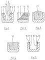
- the groove 1 open on the surface 3 of a component 2 has worn side surfaces 7, 8, whereas the groove base 6 is still in good condition and in Target position is.
- the target contour 5 of the groove 1 is shown in dash-dot lines in FIG. 1, it coincides with the actual contour 4 at the groove base 6.
- the groove 1 can in the longitudinal direction be straight and / or curved, being for the applicability of the invention it is necessary that the longitudinal edges present on the component surface 3 11, 12 or 13, 14 are at least in good approximation in one plane.
- the groove base 6 will also be flat and parallel to said plane.
- the Groove can also be closed in a ring shape.
- a straight groove 1 is shown in the present figures.
- the groove 1 widened by wear according to FIG. 1 is in a first Working step with a non-oxidic abrasive, e.g. with silicon carbide, cleaned and activated so that their surfaces 6,7,8 in a slightly roughened, Metallic bare condition without oxide layers to ensure an optimal base to form for a metallic coating. This is familiar to the person skilled in the art and therefore not shown separately.
- Figure 2 shows a partial longitudinal section through said groove 1.
- the initially open Groove end 15 is already here through a local, the entire groove cross section filling welding job 16 closed.
- the welding material is with the Component material at least the same base, e.g. based on Ti, Fe or Ni (titanium, iron or Nickel base), or preferably identical. If groove 1 is yet another, has open end, this is closed in the same way.
- Figure 3 shows the groove 1 again in cross section, this over its upper edge is also filled with solder powder 17.
- the solder powder 17 is correct with regard to its alloy composition largely matches the component material, but it is by at least one other element like boron or silicon in its Melting point reduced. In this way, the solder can be liquefied without to melt the component material.
- the solder powder 17 can for example Half of alloy powder identical to the component material, the other half made of alloy point powder with a reduced melting point and mixed with B or Si. Furthermore, wear-reducing, i.e. harder in relation to the component material or more abrasion-resistant particles of metallic or ceramic type and / or filling Metal body must be added to reduce the amount of solder powder.
- the solder powder 17 contains a certain amount of empty volume.
- the solder powder volume - including additional material - dimensioned so that it is the groove volume plus the empty volume portion of the solder powder 17 corresponds.
- the net solder volume should be without an empty volume portion - correspond to the groove volume. Possibly. existing additional material is in the Figure not shown.
- Figure 4 shows in cross section the state after the melting and solidification of the Lotes 18.
- the groove is completely filled with solid material, the metallurgical is connected to the component material. Since the solder 18 is initially in liquid form is present, it makes sense that the groove 1 must be closed at the end and in one horizontally positionable plane must have longitudinal top edges. Otherwise the groove would not be completely fillable with liquid, at least one Part of the liquefied solder would run out.
- Based on the state according to Figure 4 with solidified solder 18 can be an annealing treatment as a further process step under vacuum or in an oxygen reducing atmosphere, e.g. in hydrogen fluoride, be performed.
- the aim here is the melting point-lowering element boron or silicon by diffusion into the component material from the groove wall area remove to avoid adverse embrittlement effects. This advantageous too
- the method step does not require a separate presentation.
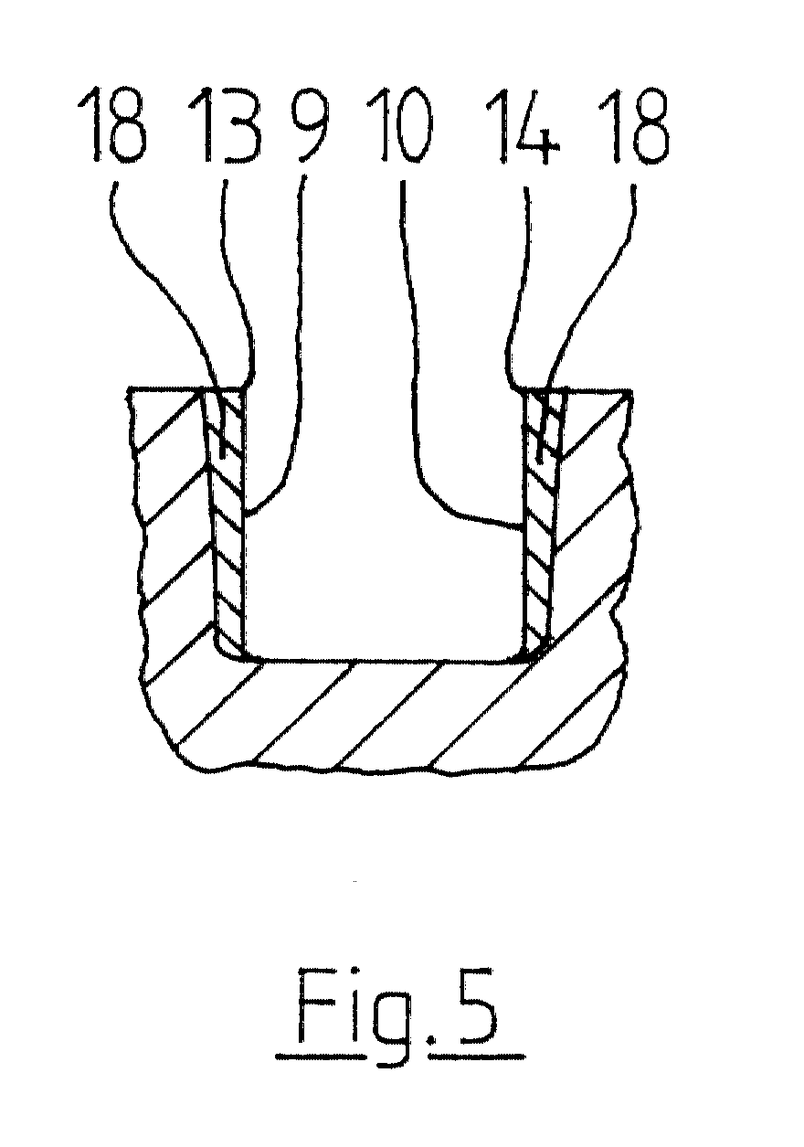
- Figure 5 finally shows that finished to the target contour, i.e. repaired Condition of the groove 1 in cross section.
- a large part of the solder 18 was removed by abrasion, for example by means of pushing, broaching, milling, turning and / or grinding.
- the side faces 9, 10 formed by the lot 18 correspond the target contour 5 in FIG. 1, in the area of the still intact groove base 6 Lot 18 completely removed. In the event of a local material deficit in this area can of course also remain solder here.
- the side solder layers are enough to the component surface 3 and include the upper longitudinal edges 13, 14 of the groove 1.
- solder layers are also elements with regard to their heat resistance best adapted to the component material, i.e. they have their solder properties practically lost and are largely identical to the component material.
Landscapes
- Engineering & Computer Science (AREA)
- Chemical & Material Sciences (AREA)
- Mechanical Engineering (AREA)
- Metallurgy (AREA)
- Organic Chemistry (AREA)
- Chemical Kinetics & Catalysis (AREA)
- Materials Engineering (AREA)
- Plasma & Fusion (AREA)
- Physics & Mathematics (AREA)
- Ceramic Products (AREA)
- Lubricants (AREA)
- Sliding-Contact Bearings (AREA)
- Electric Connection Of Electric Components To Printed Circuits (AREA)
- Arc Welding In General (AREA)
Abstract
Description
Lastaufnehmende Nuten in metallischen Bauteilen wirken in der Regel formschlüssig mit weiteren, in die Nuten eingreifenden Bauteilen zusammen. Meist sind die Paarungen nicht spielfrei und lassen Relativbewegungen zu. Daher treten nach einer gewissen Betriebsdauer u.U. Schädigungen durch plastische Verformung, Reibkorrosion, Reibverschleiß, Risse, Abplatzen etc. auf, welche in aller Regel mit einer zumindest lokalen Aufweitung des Nutquerschnitts über die Sollkontur hinaus verbunden sind. Bei hohen Bauteiltemperaturen, wie sie insbesondere in Gasturbinen auftreten, verschlechtern sich die mechanischen Eigenschaften metallischer Werkstoffe erheblich, so dass derartige Schädigungen schneller bzw. in verstärkter Form auftreten. Um nicht das gesamte, jeweilige Bauteil erneuern zu müssen, wird angestrebt, gezielt die Nut oder Nuten instandzusetzen. Hierfür sind verschiedene Verfahren in Anwendung bzw. in Erprobung, deren Gemeinsamkeiten darin bestehen, dass Werkstoff schichtartig auf die beschädigten und somit nicht mehr maßhaltigen Oberflächen der Nut mit gewissem Übermaß aufgetragen und anschließend beim Bearbeiten auf Maß teilweise wieder abgetragen wird. Als Beschichtungsverfahren kommen das Metallspritzen, das galvanische Beschichten oder das Auftragschweißen zur Anwendung. Da in der Regel die Nutseitenflächen beschädigt sind, welche sich in geringem Abstand gegenüberstehen und sich praktisch gegenseitig "abschatten", ist es schwierig bis unmöglich, hier einen ausreichenden, gleichmäßigen Werkstoffauftrag zu erzielen.
Claims (6)
- Verfahren zur Instandsetzung von metallischen Bauteilen, insbesondere für Gasturbinen, mit mechanisch lastaufnehmenden Nuten, deren an der Bauteiloberfläche vorhandene Längskanten zumindest weitgehend in einer Ebene liegen, und deren Istkontur zumindest örtlich nach Abtragen und/oder Verdrängen des Bauteilwerkstoffs von der Sollkontur abweicht, durch Aufbringen eines zumindest vorwiegend metallischen Zusatzwerkstoffes auf die NutIstkontur sowie durch abtragendes Bearbeiten auf die Sollkontur, gekennzeichnet durch folgende Verfahrensschritte je Nut:A) Mechanisches Strahlen der Nutflächen (6,7,8) mit einem nicht-oxidischen Strahlmittel,B) Verschließen offener Nutenden (15) durch Auftragschweißen (16) eines relativ zum Bauteilwerkstoff basisgleichen Schweißwerkstoffes,C) Auffüllen der endseitig verschlossenen Nut (1) mit einem relativ zum Bauteilwerkstoff basisgleichen, jedoch bei niedrigerer Temperatur schmelzenden Lotpulver (17) ohne oder mit verschleißminderndem und/oder füllendem Zusatzmaterial, wobei der Leervolumenanteil des Lotpulvers (17) ohne oder mit Zusatzmaterial durch dessen Aufhäufen über die Nutoberfläche hinaus ausgeglichen wird.D) Erhitzen des Lotpulvers (17) im Vakuum bis zur Verflüssigung und metallurgischen Verbindung mit dem Bauteilwerkstoff, wobei die Nut (1) in horizontaler, nach oben offener Lage gehalten wird, sowie Abkühlen und Erstarren im Vakuum, undE) Bearbeiten auf Sollkontur (5) durch weitgehendes Abtragen des erstarrten Lotes (18).
- Verfahren nach Anspruch 1, dadurch gekennzeichnet, dass als Strahlmittel Siliziumkarbid (SiC) verwendet wird, und dass nach dem Strahlen bedarfsweise ein Glühen in sauerstoffreduzierender Atmosphäre, z.B. in Fluorwasserstoff, durchgeführt wird.
- Verfahren nach Anspruch 1 oder 2, dadurch gekennzeichnet, dass das Lotpulver (17) - abgesehen von einem möglichen Zusatzmaterial - weitgehend mit dem Bauteilwerkstoff identisch ist und Bor (B) oder Silizium (Si) als schmelzpunktsenkendes Element enthält, wobei maximal etwa die Hälfte des Lotpulvers (17) aus reinem Bauteilwerkstoffpulver ohne schmelzpunktsenkende Elemente bestehen kann.
- Verfahren nach einem oder mehreren der Ansprüche 1 bis 3, dadurch gekennzeichnet, dass dem Lotpulver (17) als Zusatzmaterial verschleißmindernde Metall- bzw. Keramikteilchen und/oder füllende, zum Bauteilwerkstoff basisgleiche Metallkörper, z.B. Kugeln oder Drähte, zugegeben werden.
- Verfahren nach einem oder mehreren der Ansprüche 1 bis 4, dadurch gekennzeichnet, dass nach dem Verflüssigen und Erstarren des Lotes (18) in der Nut (1) eine Glühbehandlung im Vakuum erfolgt.
- Verfahren nach einem oder mehreren der Ansprüche 1 bis 5, dadurch gekennzeichnet, dass das Bearbeiten auf Sollkontur (5) spanabhebend erfolgt, z.B. durch Räumen, Stoßen, Drehen, Fräsen und/oder Schleifen.
Applications Claiming Priority (2)
| Application Number | Priority Date | Filing Date | Title |
|---|---|---|---|
| DE10030776 | 2000-06-23 | ||
| DE10030776A DE10030776C2 (de) | 2000-06-23 | 2000-06-23 | Verfahren zur Instandsetzung von metallischen Bauteilen insbesondere für Gasturbinen |
Publications (3)
| Publication Number | Publication Date |
|---|---|
| EP1166937A2 true EP1166937A2 (de) | 2002-01-02 |
| EP1166937A3 EP1166937A3 (de) | 2004-08-11 |
| EP1166937B1 EP1166937B1 (de) | 2005-08-31 |
Family
ID=7646643
Family Applications (1)
| Application Number | Title | Priority Date | Filing Date |
|---|---|---|---|
| EP01114965A Expired - Lifetime EP1166937B1 (de) | 2000-06-23 | 2001-06-20 | Verfahren zur Instandsetzung von metallischen Bauteilen |
Country Status (4)
| Country | Link |
|---|---|
| US (1) | US6626350B2 (de) |
| EP (1) | EP1166937B1 (de) |
| CA (1) | CA2351292C (de) |
| DE (2) | DE10030776C2 (de) |
Families Citing this family (20)
| Publication number | Priority date | Publication date | Assignee | Title |
|---|---|---|---|---|
| DE102004001276A1 (de) * | 2004-01-08 | 2005-08-04 | Mtu Aero Engines Gmbh | Verfahren zur Erwärmung von Bauteilen |
| DE102004003865B4 (de) * | 2004-01-26 | 2008-06-19 | Rolls-Royce Deutschland Ltd & Co Kg | Verfahren zur maßgenauen Bearbeitung von Bauteilen |
| US8844090B2 (en) | 2005-06-17 | 2014-09-30 | United Technologies Corporation | Tool for filling voids in turbine vanes and other articles |
| US8240544B2 (en) * | 2005-08-02 | 2012-08-14 | Linde Aktiengesellschaft | Introduction of nanoparticles |
| US20070068648A1 (en) * | 2005-09-28 | 2007-03-29 | Honeywell International, Inc. | Method for repairing die cast dies |
| EP2062672A1 (de) * | 2007-11-20 | 2009-05-27 | Siemens Aktiengesellschaft | Verfahren zum Löten weiter Spalte |
| US8816259B2 (en) * | 2012-04-06 | 2014-08-26 | Siemens Aktiengesellschaft | Pack heat treatment for material enhancement |
| US20140312096A1 (en) * | 2013-04-18 | 2014-10-23 | Caterpillar Inc. | Oxy-fuel weld repair of metallic components |
| US9126279B2 (en) * | 2013-09-30 | 2015-09-08 | General Electric Company | Brazing method |
| US20150126260A1 (en) * | 2013-11-01 | 2015-05-07 | Levelup Incorporated | System and method for proximity and motion detection for interactive activity |
| US20150165569A1 (en) * | 2013-12-18 | 2015-06-18 | Petya M. Georgieva | Repair of turbine engine components using waterjet ablation process |
| DE102014220362A1 (de) * | 2014-10-08 | 2016-04-14 | Siemens Aktiengesellschaft | Verschließen von Löchern mittels eines thermischen Spritzverfahrens durch ein Pulvergemisch |
| CN104722938B (zh) * | 2015-02-27 | 2017-03-01 | 东方电气集团东方锅炉股份有限公司 | 筒体缺陷焊接修复方法 |
| US20170022614A1 (en) * | 2015-07-20 | 2017-01-26 | Goodrich Corporation | Methods for repair of aircraft wheel and brake parts |
| EP3216554B1 (de) * | 2016-03-09 | 2020-05-06 | MTU Aero Engines GmbH | Bauteil mit verschleissgeschützten öffnungen und vertiefungen sowie verfahren zur herstellung derselben |
| CN110695556A (zh) * | 2019-10-23 | 2020-01-17 | 中煤张家口煤矿机械有限责任公司 | 铸硅铝换热器换热柱的修复补焊方法及装置 |
| US11453090B2 (en) | 2020-05-26 | 2022-09-27 | Raytheon Technologies Corporation | Piston seal assembly guards and inserts for seal groove |
| CN116043211A (zh) * | 2022-11-30 | 2023-05-02 | 成都青石激光科技有限公司 | 一种小内孔激光熔覆喷嘴 |
| CN118181153A (zh) * | 2024-04-22 | 2024-06-14 | 北摩高科正定摩擦材料有限公司 | 一种tc21钛合金材质飞机起落架用零部件表面喷丸强化工艺验证方法 |
| CN119457566B (zh) * | 2024-11-06 | 2025-10-31 | 中国航发沈阳黎明航空发动机有限责任公司 | 一种用于高温镍基合金蜂窝补焊的低熔点修复钎料及其制备方法 |
Family Cites Families (21)
| Publication number | Priority date | Publication date | Assignee | Title |
|---|---|---|---|---|
| DE130853C (de) | ||||
| US4008844A (en) * | 1975-01-06 | 1977-02-22 | United Technologies Corporation | Method of repairing surface defects using metallic filler material |
| US4028787A (en) * | 1975-09-15 | 1977-06-14 | Cretella Salvatore | Refurbished turbine vanes and method of refurbishment thereof |
| DD130853B1 (de) * | 1977-01-13 | 1991-03-28 | Guenter Kastner | Verfahren zur instandsetzung der kolben vorzugsweise von brennkraftmaschinen und verdichteranlagen |
| JPS6053110B2 (ja) * | 1982-11-09 | 1985-11-22 | 川崎製鉄株式会社 | 金属物体のア−ク・ガス混合溶射補修方法 |
| DE3521664A1 (de) * | 1985-06-18 | 1986-12-18 | BBC Aktiengesellschaft Brown, Boveri & Cie., Baden, Aargau | Verfahren zur befestigung von schaufeln auf dem umfang des rotorkoerpers einer dampfturbine |
| US4726104A (en) * | 1986-11-20 | 1988-02-23 | United Technologies Corporation | Methods for weld repairing hollow, air cooled turbine blades and vanes |
| US4878953A (en) * | 1988-01-13 | 1989-11-07 | Metallurgical Industries, Inc. | Method of refurbishing cast gas turbine engine components and refurbished component |
| US4826071A (en) * | 1988-04-25 | 1989-05-02 | Harris Graphics | Stainless steel weld clad cylinder interconnected by a groove and gap also weld covered by stainless steel |
| US5048183A (en) * | 1988-08-26 | 1991-09-17 | Solar Turbines Incorporated | Method of making and repairing turbine blades |
| US4982066A (en) * | 1989-12-11 | 1991-01-01 | Bird-Johnson Company | Method of rehabilitating propeller hub bodies |
| GB2271521B (en) * | 1992-10-06 | 1996-01-31 | Metalock | Reconditioning engine parts |
| US5522134A (en) * | 1994-06-30 | 1996-06-04 | United Technologies Corporation | Turbine vane flow area restoration method |
| US5914055A (en) * | 1996-11-18 | 1999-06-22 | Tennessee Valley Authority | Rotor repair system and technique |
| US5873703A (en) * | 1997-01-22 | 1999-02-23 | General Electric Company | Repair of gamma titanium aluminide articles |
| US5794338A (en) * | 1997-04-04 | 1998-08-18 | General Electric Company | Method for repairing a turbine engine member damaged tip |
| US5762727A (en) * | 1997-04-14 | 1998-06-09 | General Electric Company | Weld repair process and article repaired thereby |
| US6338765B1 (en) * | 1998-09-03 | 2002-01-15 | Uit, L.L.C. | Ultrasonic impact methods for treatment of welded structures |
| US6332272B1 (en) * | 2000-01-07 | 2001-12-25 | Siemens Westinghouse Power Corporation | Method of repairing a turbine blade |
| US6376801B1 (en) * | 2000-10-12 | 2002-04-23 | General Electric Company | Gas turbine component refurbishment apparatus and repair method |
| DE10055505C2 (de) * | 2000-11-10 | 2003-03-20 | Mtu Aero Engines Gmbh | Verfahren zur Instandsetzung von Schaufeln |
-
2000
- 2000-06-23 DE DE10030776A patent/DE10030776C2/de not_active Expired - Fee Related
-
2001
- 2001-06-20 EP EP01114965A patent/EP1166937B1/de not_active Expired - Lifetime
- 2001-06-20 DE DE50107254T patent/DE50107254D1/de not_active Expired - Lifetime
- 2001-06-22 CA CA002351292A patent/CA2351292C/en not_active Expired - Fee Related
- 2001-06-25 US US09/887,544 patent/US6626350B2/en not_active Expired - Fee Related
Also Published As
| Publication number | Publication date |
|---|---|
| DE10030776A1 (de) | 2002-02-21 |
| CA2351292C (en) | 2009-09-01 |
| EP1166937B1 (de) | 2005-08-31 |
| US20020020734A1 (en) | 2002-02-21 |
| CA2351292A1 (en) | 2001-12-23 |
| EP1166937A3 (de) | 2004-08-11 |
| US6626350B2 (en) | 2003-09-30 |
| DE10030776C2 (de) | 2002-06-20 |
| DE50107254D1 (de) | 2005-10-06 |
Similar Documents
| Publication | Publication Date | Title |
|---|---|---|
| EP1166937B1 (de) | Verfahren zur Instandsetzung von metallischen Bauteilen | |
| EP2188416B1 (de) | Verfahren zur reparatur eines bauteils durch beschichten | |
| DE2722263A1 (de) | Verfahren zur erneuernden oberflaechenbehandlung von turbinen-komponenten u.dgl. | |
| DE2640755A1 (de) | Verfahren zur erneuernden oberflaechenbehandlung von aerodynamischen turbinen-komponenten, wie laufschaufeln und leitschaufeln | |
| DE102016115676A1 (de) | Additive Fertigung | |
| EP0866741B1 (de) | Verfahren zur aufschweissung der schienen | |
| DE1937974A1 (de) | Verbundgusswalze | |
| DE102005047035B3 (de) | Verfahren zur Herstellung eines Kolbens für einen Verbrennungsmotor sowie danach hergestellter Kolben | |
| EP1219375B1 (de) | Verfahren zum Reparieren von Schadstellen an einem Metallbauteil | |
| DE10310130A1 (de) | Herstellungsverfahren für eine Zylinderblock-Einheit | |
| DE2630541A1 (de) | Verfahren zur herstellung eines aluminium-gussteiles mit verschleissfesten oberflaechenpartien | |
| EP1135226B1 (de) | Verbundgussteil und verfahren zu seiner herstellung | |
| DE821902C (de) | Verfahren zum Aufspritzen von metallischen UEberzuegen | |
| DE1615386A1 (de) | Lichtbogenschweissverfahren | |
| DE102015214613A1 (de) | Verfahren zum Reparieren einer wenigstens einen Hohlraum aufweisenden Schaufel einer Gasturbine | |
| EP2170780A2 (de) | Hartstoffkörper für formgussteile und verfahren zu seiner herstellung | |
| DE102007010839B4 (de) | Verfahren zur Herstellung eines Kolbens und Kolben mit einer ringförmigen Verstärkung bestehend aus mehreren Verstärkungssegmenten | |
| EP1186358A2 (de) | Verfahren und Platine zur Herstellung eines kaltumgeformten Bauteils aus Stahlblech und Verwendung einer Platine | |
| EP3160664B1 (de) | Walze und verfahren zum herstellen einer walze zum warm- oder kaltwalzen von metallflachprodukten | |
| DE102018123916A1 (de) | Additives Herstellungsverfahren für ein Bauteil | |
| DE102012025140A1 (de) | Reibrührwerkzeug, Herstellverfahren hierfür und Reibrührverfahren | |
| DE69821198T2 (de) | Verfahren zur Herstellung einer bimetallischen Turbinenschaufel und Verwendung | |
| DE4130202C2 (de) | Walze für das Stranggießen von Metallen, insbesondere von Stahl und Verfahren zur Herstellung einer derartigen Walze | |
| DE10060674A1 (de) | Formvorrichtung zum Herstellen von Gefäßen aus Glas sowie Verfahren zur Erzeugung einer solchen Formvorrichtung | |
| AT411877B (de) | Composite-flachstab |
Legal Events
| Date | Code | Title | Description |
|---|---|---|---|
| PUAI | Public reference made under article 153(3) epc to a published international application that has entered the european phase |
Free format text: ORIGINAL CODE: 0009012 |
|
| AK | Designated contracting states |
Kind code of ref document: A2 Designated state(s): AT BE CH CY DE DK ES FI FR GB GR IE IT LI LU MC NL PT SE TR |
|
| AX | Request for extension of the european patent |
Free format text: AL;LT;LV;MK;RO;SI |
|
| PUAL | Search report despatched |
Free format text: ORIGINAL CODE: 0009013 |
|
| AK | Designated contracting states |
Kind code of ref document: A3 Designated state(s): AT BE CH CY DE DK ES FI FR GB GR IE IT LI LU MC NL PT SE TR |
|
| AX | Request for extension of the european patent |
Extension state: AL LT LV MK RO SI |
|
| 17P | Request for examination filed |
Effective date: 20040723 |
|
| GRAP | Despatch of communication of intention to grant a patent |
Free format text: ORIGINAL CODE: EPIDOSNIGR1 |
|
| AKX | Designation fees paid |
Designated state(s): DE FR GB IT |
|
| GRAS | Grant fee paid |
Free format text: ORIGINAL CODE: EPIDOSNIGR3 |
|
| GRAA | (expected) grant |
Free format text: ORIGINAL CODE: 0009210 |
|
| AK | Designated contracting states |
Kind code of ref document: B1 Designated state(s): DE FR GB IT |
|
| RBV | Designated contracting states (corrected) |
Designated state(s): DE FR GB IT |
|
| REG | Reference to a national code |
Ref country code: GB Ref legal event code: FG4D Free format text: NOT ENGLISH |
|
| REF | Corresponds to: |
Ref document number: 50107254 Country of ref document: DE Date of ref document: 20051006 Kind code of ref document: P |
|
| GBT | Gb: translation of ep patent filed (gb section 77(6)(a)/1977) |
Effective date: 20051114 |
|
| ET | Fr: translation filed | ||
| PLBE | No opposition filed within time limit |
Free format text: ORIGINAL CODE: 0009261 |
|
| STAA | Information on the status of an ep patent application or granted ep patent |
Free format text: STATUS: NO OPPOSITION FILED WITHIN TIME LIMIT |
|
| 26N | No opposition filed |
Effective date: 20060601 |
|
| PGFP | Annual fee paid to national office [announced via postgrant information from national office to epo] |
Ref country code: GB Payment date: 20140620 Year of fee payment: 14 |
|
| PGFP | Annual fee paid to national office [announced via postgrant information from national office to epo] |
Ref country code: DE Payment date: 20140625 Year of fee payment: 14 Ref country code: IT Payment date: 20140626 Year of fee payment: 14 |
|
| PGFP | Annual fee paid to national office [announced via postgrant information from national office to epo] |
Ref country code: FR Payment date: 20140617 Year of fee payment: 14 |
|
| REG | Reference to a national code |
Ref country code: DE Ref legal event code: R119 Ref document number: 50107254 Country of ref document: DE |
|
| PG25 | Lapsed in a contracting state [announced via postgrant information from national office to epo] |
Ref country code: IT Free format text: LAPSE BECAUSE OF NON-PAYMENT OF DUE FEES Effective date: 20150620 |
|
| GBPC | Gb: european patent ceased through non-payment of renewal fee |
Effective date: 20150620 |
|
| REG | Reference to a national code |
Ref country code: FR Ref legal event code: ST Effective date: 20160229 |
|
| PG25 | Lapsed in a contracting state [announced via postgrant information from national office to epo] |
Ref country code: GB Free format text: LAPSE BECAUSE OF NON-PAYMENT OF DUE FEES Effective date: 20150620 Ref country code: DE Free format text: LAPSE BECAUSE OF NON-PAYMENT OF DUE FEES Effective date: 20160101 |
|
| PG25 | Lapsed in a contracting state [announced via postgrant information from national office to epo] |
Ref country code: FR Free format text: LAPSE BECAUSE OF NON-PAYMENT OF DUE FEES Effective date: 20150630 |