EP1166932A1 - Spindle in a machine tool - Google Patents
Spindle in a machine tool Download PDFInfo
- Publication number
- EP1166932A1 EP1166932A1 EP01113246A EP01113246A EP1166932A1 EP 1166932 A1 EP1166932 A1 EP 1166932A1 EP 01113246 A EP01113246 A EP 01113246A EP 01113246 A EP01113246 A EP 01113246A EP 1166932 A1 EP1166932 A1 EP 1166932A1
- Authority
- EP
- European Patent Office
- Prior art keywords
- spindle according
- crown
- spindle
- guide
- segments
- Prior art date
- Legal status (The legal status is an assumption and is not a legal conclusion. Google has not performed a legal analysis and makes no representation as to the accuracy of the status listed.)
- Granted
Links
Images


Classifications
-
- B—PERFORMING OPERATIONS; TRANSPORTING
- B23—MACHINE TOOLS; METAL-WORKING NOT OTHERWISE PROVIDED FOR
- B23B—TURNING; BORING
- B23B31/00—Chucks; Expansion mandrels; Adaptations thereof for remote control
- B23B31/02—Chucks
- B23B31/24—Chucks characterised by features relating primarily to remote control of the gripping means
- B23B31/26—Chucks characterised by features relating primarily to remote control of the gripping means using mechanical transmission through the working-spindle
- B23B31/261—Chucks characterised by features relating primarily to remote control of the gripping means using mechanical transmission through the working-spindle clamping the end of the toolholder shank
- B23B31/265—Chucks characterised by features relating primarily to remote control of the gripping means using mechanical transmission through the working-spindle clamping the end of the toolholder shank by means of collets
-
- Y—GENERAL TAGGING OF NEW TECHNOLOGICAL DEVELOPMENTS; GENERAL TAGGING OF CROSS-SECTIONAL TECHNOLOGIES SPANNING OVER SEVERAL SECTIONS OF THE IPC; TECHNICAL SUBJECTS COVERED BY FORMER USPC CROSS-REFERENCE ART COLLECTIONS [XRACs] AND DIGESTS
- Y10—TECHNICAL SUBJECTS COVERED BY FORMER USPC
- Y10T—TECHNICAL SUBJECTS COVERED BY FORMER US CLASSIFICATION
- Y10T408/00—Cutting by use of rotating axially moving tool
- Y10T408/94—Tool-support
- Y10T408/95—Tool-support with tool-retaining means
- Y10T408/953—Clamping jaws
-
- Y—GENERAL TAGGING OF NEW TECHNOLOGICAL DEVELOPMENTS; GENERAL TAGGING OF CROSS-SECTIONAL TECHNOLOGIES SPANNING OVER SEVERAL SECTIONS OF THE IPC; TECHNICAL SUBJECTS COVERED BY FORMER USPC CROSS-REFERENCE ART COLLECTIONS [XRACs] AND DIGESTS
- Y10—TECHNICAL SUBJECTS COVERED BY FORMER USPC
- Y10T—TECHNICAL SUBJECTS COVERED BY FORMER US CLASSIFICATION
- Y10T409/00—Gear cutting, milling, or planing
- Y10T409/30—Milling
- Y10T409/309352—Cutter spindle or spindle support
- Y10T409/309408—Cutter spindle or spindle support with cutter holder
- Y10T409/309464—Cutter spindle or spindle support with cutter holder and draw bar
-
- Y—GENERAL TAGGING OF NEW TECHNOLOGICAL DEVELOPMENTS; GENERAL TAGGING OF CROSS-SECTIONAL TECHNOLOGIES SPANNING OVER SEVERAL SECTIONS OF THE IPC; TECHNICAL SUBJECTS COVERED BY FORMER USPC CROSS-REFERENCE ART COLLECTIONS [XRACs] AND DIGESTS
- Y10—TECHNICAL SUBJECTS COVERED BY FORMER USPC
- Y10T—TECHNICAL SUBJECTS COVERED BY FORMER US CLASSIFICATION
- Y10T82/00—Turning
- Y10T82/25—Lathe
- Y10T82/2552—Headstock
- Y10T82/2562—Spindle and bearings
-
- Y—GENERAL TAGGING OF NEW TECHNOLOGICAL DEVELOPMENTS; GENERAL TAGGING OF CROSS-SECTIONAL TECHNOLOGIES SPANNING OVER SEVERAL SECTIONS OF THE IPC; TECHNICAL SUBJECTS COVERED BY FORMER USPC CROSS-REFERENCE ART COLLECTIONS [XRACs] AND DIGESTS
- Y10—TECHNICAL SUBJECTS COVERED BY FORMER USPC
- Y10T—TECHNICAL SUBJECTS COVERED BY FORMER US CLASSIFICATION
- Y10T82/00—Turning
- Y10T82/25—Lathe
- Y10T82/2585—Tool rest
- Y10T82/2589—Quick release tool or holder clamp
Definitions
- the invention relates to a spindle in a machine tool with an axis, with a receptacle lying in the axis for a shaft of a tool holder and with a clamping mechanism for axially fixing the shaft in the receptacle, wherein the clamping mechanism has an axially displaceable mandrel as well at least one arranged on a circumference of the mandrel Segment contains that with axial displacement of the mandrel by means of one acting between the mandrel and the segments first guide between a first and a second radial Operating position is axially movable and in the first Operating position, the shaft is positively fixed in the holder.
- a spindle with such a clamping mechanism is known for example from machining centers of the "FZ" type series Applicant.
- the tool holder is included its outer cone in a complementary inner conical receptacle of the spindle head.
- a mandrel of the clamping mechanism then dips into a corresponding receptacle in the shaft of the Tool holder.
- the mandrel is arranged axially Drawbar axially movable.
- the mandrel is in an advanced position Operating position.
- On the outer circumference of the mandrel are over the Several segments arranged around the circumference. The segments are running at the front end into a thickened head that turns into this operating position is located radially inside.
- the invention is based on the object, a To further develop the spindle of the type mentioned at the beginning that the above problems are avoided.
- the spindle of the type mentioned at the beginning is intended to securely engage the tool holder in the Spindle reached and there should be damage to the elements of the tensioning mechanism can be avoided.
- This task is the spindle of the type mentioned solved according to the invention in that a second guide is provided is by means of which the at least one segment in the second Operating position and in any intermediate position between the first and the second operating position kept defined becomes.
- the second tour ensures that all segments are always in a defined position, including and straight in the two operating positions, the radial end positions correspond. In this way it is ensured that a new tool holder always under defined conditions can be inserted with its shaft into the spindle can and there after a short search of the spindle holder with the Coupling speed also the positive connection between Sliding block and groove is made so that the tool holder is not only clamped in the correct angular position but also a reliable non-positive connection in the area of the conical seat between the shaft and the receptacle.
- the at least one segment extends along the axis, the first guide at both axial ends and the second guide only engages at one axial end of the segment.
- This measure has the advantage that the second leadership on the necessary minimum can be limited and thereby an inexpensive and structurally simple solution is possible.
- This measure has the advantage that the elements of the second Guide can be moved backwards into the spindle, so that no disturbing installations are required in the front area are.
- the guides are designed as inclined guides, wherein the at least one segment is preferably one in radial section has a substantially circular arc shape and the diagonal guides are formed by conical bevels.
- such a crown provides that they have a cylindrical portion holding the spring and has a plurality of axially protruding shoes, on which the first conical bevels are formed.
- first / second Slant opposite to the third / fourth Is inclined it is further preferred if the first / second Slant opposite to the third / fourth Is inclined.
- This measure has the advantage of being directed differently Forces the desired mounting of the elements in the Intermediate positions and safe in the second operating position can be guaranteed.
- the sleeve is axially fixed.
- This measure has the advantage that a particularly simple sequence of movements arises because there is no separate one for the second tour Power source or power dissipation is required there rather, it is sufficient if the sleeve is supported on the spindle can.
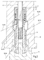
- 10 as a whole denotes a spindle one Machine tool, for example a machining center, how to run program controlled drilling, milling and other work is used.
- the spindle 10 includes one Spindle head 12 according to the embodiment shown points below. However, this is not to be understood as limiting because machine tools with a horizontal-axis spindle are also known are.
- a tool holder 14 is held in the spindle head 12, of which 1 and 2 only the upper end is indicated by dash-dotted lines is. Serves to retract and hold the tool holder 14 a collet 16, which has a mandrel 18 at the lower end.
- the mandrel 18 has a first at its lower end Recording 20, in which a pin 22 of the tool holder 14 engages.
- the tool holder 14 has a shaft with a at the upper end Outer cone, the outer cone 30 is the conical outer peripheral surface a neck 32 forms.
- the neck 32 is with one Provide undercut 33.
- the spindle head 12 is on his provide a third receptacle at the downward end, which is formed by an inner cone 34.
- the collet 16 is in its rear region 40 with a Provided internal thread 42 into which a pull rod 41 is screwed is.
- All of the aforementioned elements are essentially rotationally symmetrical formed with respect to an axis 46 of the Spindle 10.
- the pull rod 44 can in the direction of the axis 46 in a known per se Moved way, as indicated by an arrow 48.
- the mandrel 18 is somewhat at its lower end in FIGS. 1 and 2 thickened, with a first in the transition area to thickening Slant 50 is attached. Runs from the first slope 50 the collet 16 then in the axial direction upwards in a cylindrical portion 52 to then over a second Taper 54 again.
- Segments 60 on. Segments of this type are known per se. In practice, a plurality of such segments are placed over the Provided circumference of the mandrel 18 evenly distributed.
- the segments 60 are thickened at their lower end Provide head 62. On the inside is a third slope 64 formed, which are complementary to the first slope 50 is.
- the segments 60 then close upward a middle section 65 which is radially relatively thin is trained.
- the middle section 65 follows then at the top a guide section 66, which in turn is radially thicker is designed.
- the guide section 66 is in Fig. 3 on an enlarged scale and presented in perspective to help understand the invention to facilitate.
- the guide section 66 accordingly has a fourth bevel 68 on the outside of the segments 60 and in the illustrated embodiment in the axial direction extends upwards and outwards.
- a fifth bevel 70 is complementary to the housing of the spindle head 12 is formed.
- a sixth slope 72 is at the top of the guide section 66 provided, this sixth slope 72 opposite to the fourth slope 68, i.e. directed upwards and inwards is.
- a crown 80 To fix the segments 60 in the circumferential direction and to their axial guidance is in the rear area of the receiving opening of the Spindle head 12 also provided a crown 80.
- the crown 80 is provided on its circumference with axial slots into which the Guide sections 66 of the segments 60 engage and partially run in it.
- the crown 80 is upward with a cylindrical section 82 provided that in a complementary bore 84 on upper end of the receiving opening of the spindle head 12 runs.
- the crown 80 is axially downward by a plurality of first shoes 86 formed.
- a return spring 88 is axial Direction between the back of the first shoes 86 and a pot 90 held the top of the receiving bore forms in the spindle head 12.
- the first shoes 86 with a ninth are axially downward Provide slope 92, which is complementary to the sixth slope 72 is trained.
- the crown 80 is still in the axial region a sleeve 96 which is axially fixed up against the pot 90th supported.
- the sleeve 96 is down with a plurality of provided second shoes 98, the tenth down Have slope 100.
- the tenth slope 100 is complementary to the seventh slope 76.
- the sleeve 96 is located radially inside and the crown 80 radially outside.
- FIG. 1 shows the state the spindle 10, in which the tool holder 14 has not yet been clamped is. Rather, the tool holder 14 is only loose inserted from below into the receiving opening of the spindle head 12 until the tool holder 14 and the spindle head 12 lie against each other in the radial plane 36.
- This pulling motion causes the segments 60 to be axially relative move to mandrel 18.
- the segments 60 are namely axially movable relative to the mandrel 18.
- the thickened heads 62 slide of the segments 60 on the guidance of the slopes 50/64 on the thickened lower end of the mandrel 18 and thus radially outward.
- the thickened heads Place 62 in the undercut 33 and thus the tool holder 14 in the spindle head 12.
- the segments 60 are also at their axially upper End moved radially outwards.
- this is achieved by that the mandrel 18 with the second slope 54 on his axially rear end on the eighth slope 78 at the bottom and inner end of the guide section 66 runs and the guide section 66 simultaneously with its bottom and outside, fourth slope 68 to the fifth slope 70 in the housing of the spindle head 12.
- the spindle 10 is now in the second operating position 2, in which the tool holder 14 firmly in the Spindle head 12 is clamped.
- an intermediate position can remain an additional one Leadership provided both in the first operating position 1 as in all intermediate positions acts up to the second operating position according to FIG. 2.
- This further guidance is composed by the seventh slope 76 formed with the tenth slope 100.
Abstract
Description
Die Erfindung betrifft eine Spindel in einer Werkzeugmaschine mit einer Achse, mit einer in der Achse liegenden Aufnahme für einen Schaft eines Werkzeughalters und mit einem Spannmechanismus zum axialen Fixieren des Schaftes in der Aufnahme, wobei der Spannmechanismus einen axial verschiebbaren Spanndorn sowie mindestens ein auf einem Umfang des Spanndorns angeordnetes Segment enthält, das bei axialer Verschiebung des Spanndorns mittels einer zwischen dem Spanndorn und den Segmenten wirkenden ersten Führung zwischen einer ersten und einer zweiten radialen Betriebsstellung axial bewegbar ist und in der ersten Betriebsstellung den Schaft formschlüssig in der Aufnahme fixiert.The invention relates to a spindle in a machine tool with an axis, with a receptacle lying in the axis for a shaft of a tool holder and with a clamping mechanism for axially fixing the shaft in the receptacle, wherein the clamping mechanism has an axially displaceable mandrel as well at least one arranged on a circumference of the mandrel Segment contains that with axial displacement of the mandrel by means of one acting between the mandrel and the segments first guide between a first and a second radial Operating position is axially movable and in the first Operating position, the shaft is positively fixed in the holder.
Eine Spindel mit einem derartigen Spannmechanismus ist bekannt, beispielsweise aus Bearbeitungszentren der Typenreihe "FZ" der Anmelderin.A spindle with such a clamping mechanism is known for example from machining centers of the "FZ" type series Applicant.
Bei den bekannten Spannmechanismen wird der Werkzeughalter mit seinem Außenkegel in eine komplementäre innenkegelige Aufnahme des Spindelkopfs eingeschoben. Ein Spanndorn des Spannmechanismus taucht dann in eine entsprechende Aufnahme im Schaft des Werkzeughalters ein. Der Spanndorn ist mittels einer axial angeordneten Zugstange axial verfahrbar. Zum Einspannen des Werkzeughalters befindet sich der Spanndorn in einer vorgeschobenen Betriebsstellung. Am Außenumfang des Spanndorns sind über den Umfang verteilt mehrere Segmente angeordnet. Die Segmente laufen am vorderen Ende in eine verdickten Kopf aus, der sich in dieser Betriebsstellung radial innen befindet. Wenn nun nach dem Einschieben des Schaftes in die Aufnahme des Spindelkopfes die Zugstange eingezogen wird, wird der Spanndorn mitgenommen. Über ein System von Gleitschrägen bewegen sich dann die Segmente radial nach außen. Die verdickten Köpfe der Segmente greifen dann hinter entsprechende Vorsprünge in der Aufnahme im Schaft des Werkzeughalters, so daß dieser formschlüssig axial fixiert wird.In the known clamping mechanisms, the tool holder is included its outer cone in a complementary inner conical receptacle of the spindle head. A mandrel of the clamping mechanism then dips into a corresponding receptacle in the shaft of the Tool holder. The mandrel is arranged axially Drawbar axially movable. For clamping the tool holder the mandrel is in an advanced position Operating position. On the outer circumference of the mandrel are over the Several segments arranged around the circumference. The segments are running at the front end into a thickened head that turns into this operating position is located radially inside. If now after the insertion of the shaft into the holder of the spindle head the drawbar is retracted, the mandrel is taken along. The segments then move over a system of sliding slopes radially outwards. The thickened heads of the segments grip then behind corresponding projections in the receptacle in the shaft of the tool holder so that it is axially positively fixed becomes.
In axialer Richtung hinter dem Spanndorn befindet sich eine Krone mit mehreren über den Umfang verteilten Ausnehmungen, in denen die rückwärtigen Enden der Segmente gehalten sind. Die Krone liegt über weitere Führungsschrägen an den Segmenten an. Beim Spannen des Spannmechanismus wird die Krone gegen die Kraft einer Feder nach hinten geschoben. Beim Entspannen des Spannmechanismus drückt die Feder die Krone wieder nach vorne, wobei die Schrägführung zwischen Krone und Segmenten bewirkt, daß diese wieder in ihre radial innere Betriebsstellung gelangen.There is one in the axial direction behind the mandrel Crown with several recesses distributed over the circumference, in which the rear ends of the segments are held. The Krone is in contact with the segments via further management grants. When the tensioning mechanism is tensioned, the crown is pressed against the Pushed back by a spring. When relaxing the Tensioning mechanism pushes the spring forward the crown again, the sloping between crown and segments that they return to their radially inner operating position.
Bei diesen herkömmlichen Spannmechanismen kann nun eine Fehlfunktion dadurch auftreten, daß die Segmente sowohl in ihrer radial inneren Betriebsstellung (bei entspanntem Spannmechanismus) wie auch in den Zwischenpositionen zwischen den beiden Betriebsstellungen undefinierte Lagen einnehmen. Dies gilt insbesondere für das axial vordere Ende der Segmente. Diese könnten beispielsweise nicht in ihre radial innere Betriebsstellung zurückkehren, obwohl die Segmente vom hinteren Ende her durch die unter Federkraft vorlaufende Krone entsprechend bewegt werden. Wenn dann die Segmente mit ihrem vorderen Ende in einer undefinierten Lage sind, kann es beim Einsetzen des nächsten Werkzeughalters zu Fehlfunktionen kommen. Insbesondere kann bereits eine formschlüssige Verbindung zwischen Werkzeughalter und Spindelaufnahme hergestellt werden, die bewirkt, daß der Werkzeughalter bereits in diesem Zeitpunkt von der mit langsamer Kupplungsdrehzahl umlaufenden Aufnahme der Spindel mitgenommen wird. Dann kann aber die herkömmliche Verbindung zwischen einem Nutenstein und einer Nut zwischen Aufnahme und Werkzeughalter nicht eingreifen, so daß keine arbeitsfähige Verbindung zwischen Werkzeughalter und Spindel hergestellt wird. A malfunction can now occur with these conventional clamping mechanisms occur in that the segments in both radially inner operating position (with relaxed clamping mechanism) as well as in the intermediate positions between the two operating positions take undefined positions. This is especially true for the axially front end of the segments. These could for example, do not return to their radially inner operating position, although the segments from the rear end through the the spring leading crown can be moved accordingly. Then if the segments with their front end in an undefined Position, it can occur when inserting the next tool holder malfunctions occur. In particular, can already a positive connection between the tool holder and Spindle receptacles are made, which causes the tool holder already at this point in time from the slow one Coupling speed revolving receptacle of the spindle becomes. But then the conventional connection between one Sliding block and a groove between the holder and tool holder do not intervene so that there is no working connection between Tool holder and spindle is manufactured.
Außerdem kann bei derartig undefinierten Situationen eine Beschädigung der Segmente eintreten.Damage can also occur in such undefined situations of the segments occur.
Der Erfindung liegt demgegenüber die Aufgabe zugrunde, eine Spindel der eingangs genannten Art dahingehend weiterzubilden, daß die vorstehend genannten Probleme vermieden werden. Insbesondere soll ein sicheres Einkuppeln des Werkzeughalters in die Spindel erreicht und es sollen Beschädigungen an den Elementen des Spannmechanismus vermieden werden.The invention is based on the object, a To further develop the spindle of the type mentioned at the beginning that the above problems are avoided. In particular is intended to securely engage the tool holder in the Spindle reached and there should be damage to the elements of the tensioning mechanism can be avoided.
Diese Aufgabe wird bei der Spindel der eingangs genannten Art erfindungsgemäß dadurch gelöst, daß eine zweite Führung vorgesehen ist, mittels der das mindestens eine Segment in der zweiten Betriebsstellung sowie in jeder Zwischenposition zwischen der ersten und der zweiten Betriebsstellung definiert gehalten wird.This task is the spindle of the type mentioned solved according to the invention in that a second guide is provided is by means of which the at least one segment in the second Operating position and in any intermediate position between the first and the second operating position kept defined becomes.
Die der Erfindung zugrunde liegende Aufgabe wird auf diese Weise vollkommen gelöst.The object underlying the invention is achieved in this way completely solved.
Die zweite Führung gewährleistet nämlich, daß sich alle Segmente stets in einer definierten Position befinden, also auch und gerade in den beiden Betriebsstellungen, die den radialen Endlagen entsprechen. Es ist auf diese Weise sichergestellt, daß ein neuer Werkzeughalter immer unter definierten Bedingungen mit seinem Schaft in die Aufnahme der Spindel eingesetzt werden kann und dort nach kurzem Suchlauf der Spindelaufnahme mit der Kupplungsdrehzahl auch die formschlüssige Verbindung zwischen Nutenstein und Nut hergestellt wird, so daß der Werkzeughalter nicht nur in der richtigen Winkellage eingespannt ist sondern auch eine zuverlässige kraftschlüssige Verbindung im Bereich des Kegelsitzes zwischen Schaft und Aufnahme hergestellt ist.The second tour ensures that all segments are always in a defined position, including and straight in the two operating positions, the radial end positions correspond. In this way it is ensured that a new tool holder always under defined conditions can be inserted with its shaft into the spindle can and there after a short search of the spindle holder with the Coupling speed also the positive connection between Sliding block and groove is made so that the tool holder is not only clamped in the correct angular position but also a reliable non-positive connection in the area of the conical seat between the shaft and the receptacle.
Bei einer bevorzugten Weiterbildung der erfindungsgemäßen Spindel erstreckt sich das mindestens eine Segment entlang der Achse, wobei die erste Führung an beiden axialen Enden und die zweite Führung nur an einem axialen Ende des Segments angreift.In a preferred development of the spindle according to the invention the at least one segment extends along the axis, the first guide at both axial ends and the second guide only engages at one axial end of the segment.
Diese Maßnahme hat den Vorteil, daß die zweite Führung auf das notwendige Minimum beschränkt werden kann und dadurch eine kostengünstige und baulich einfache Lösung möglich ist.This measure has the advantage that the second leadership on the necessary minimum can be limited and thereby an inexpensive and structurally simple solution is possible.
Bei einer bevorzugten Weiterbildung des vorgenannten Ausführungsbeispiels greift die zweite Führung am von der Aufnahme wegweisenden axialen Ende des mindestens einen Segments an.In a preferred development of the aforementioned embodiment grabs the second guide from the reception groundbreaking axial end of the at least one segment.
Diese Maßnahme hat den Vorteil, daß die Elemente der zweiten Führung nach hinten in die Spindel verlegt werden können, so daß im vorderen Bereich keine störenden Einbauten erforderlich sind.This measure has the advantage that the elements of the second Guide can be moved backwards into the spindle, so that no disturbing installations are required in the front area are.
Bei einem weiteren bevorzugten Ausführungsbeispiel der Erfindung greift die ersten Führung in der zweiten Betriebsstellung nur am von der Aufnahme wegweisenden axialen Ende des mindestens einen Segments an.In a further preferred embodiment of the invention grips the first guide in the second operating position only at the axial end of the at least pointing away from the receptacle a segment.
Diese dem Stand der Technik entsprechende Merkmalsgruppe hat sich in der Praxis bewährt und bedeutet, daß die erfindungsgemäß vorgesehenen Maßnahmen auch bei im übrigen herkömmlichen Spannmechanismen eingesetzt und diese gegebenenfalls auch nachgerüstet werden können. This group of features corresponding to the prior art has proven itself in practice and means that the invention planned measures also in the other conventional Clamping mechanisms used and if necessary also retrofitted can be.
Bei einer weiteren Ausführungsform der Erfindung ist vorgesehen, daß die Führungen als Schrägführungen ausgebildet sind, wobei das mindestens eine Segment vorzugsweise eine im Radialschnitt im wesentlichen kreisbogenförmige Gestalt aufweist und die Schrägführungen durch konische Schrägen gebildet werden.In a further embodiment of the invention, that the guides are designed as inclined guides, wherein the at least one segment is preferably one in radial section has a substantially circular arc shape and the diagonal guides are formed by conical bevels.
Diese Maßnahmen haben den Vorteil, daß an sich bekannte und bewährte Elemente für die Schrägführungen eingesetzt werden können. Mittels einer einzigen axial gerichteten Kraft lassen sich auf diese Weise alle Führungsbewegungen erzeugen bzw. davon ableiten.These measures have the advantage that they are known and proven Elements for the inclined guides can be used. With a single axially directed force generate or derive all leadership movements in this way.
Im Rahmen der vorliegenden Erfindung ist in an sich bekannter Weise bevorzugt, wenn eine Mehrzahl von Segmenten über einen Außenumfang des Spanndorns verteilt angeordnet sind.Within the scope of the present invention is known per se Way preferred if a plurality of segments over a The outer circumference of the mandrel is distributed.
Dann ist ebenfalls in Übereinstimmung mit bekannten Anordnungen bevorzugt, wenn die Segmente an ihrem von der Aufnahme abgewandten Ende in einer gemeinsamen Krone gehalten sind, wobei die Krone mit ersten konischen Schrägen versehen ist, die mit zweiten konischen Schrägen an den Segmenten als Bestandteil der ersten Führung zusammenarbeiten.Then it is also in accordance with known arrangements preferred if the segments on their facing away from the recording End held in a common crown, being the crown is provided with the first conical bevels with second conical bevels on the segments as part of the first leadership work together.
Auch hier gilt, daß in vorteilhafter Weise bei der Erfindung möglich ist, eine Vielzahl von bewährten konstruktiven Elementen beizubehalten.Here too, that applies in an advantageous manner to the invention is possible a variety of proven design elements maintain.
Dies gilt unter anderem auch dafür, daß die Krone beim axialen Verschieben des Spanndorns gegen die Kraft einer Feder axial verspannt wird, wobei weiter vorzugsweise die Feder in der zweiten Betriebsstellung entspannt ist. This also applies to the fact that the crown is in the axial Axial displacement of the mandrel against the force of a spring is clamped, further preferably the spring in the second operating position is relaxed.
Schließlich ist bei einer derartigen Krone erfindungsgemäß vorgesehen, daß sie einen die Feder haltenden zylindrischen Abschnitt sowie eine Mehrzahl von axial vorstehenden Schuhen aufweist, an denen die ersten konischen Schrägen angeformt sind.Finally, according to the invention, such a crown provides that they have a cylindrical portion holding the spring and has a plurality of axially protruding shoes, on which the first conical bevels are formed.
Im Rahmen der vorliegenden Erfindung wird nun weiterhin in vorteilhafter Weise vorgesehen, daß im axialen Bereich der Krone eine zur Krone koaxial ausgebildete Hülse angeordnet ist, wobei die Hülse mit dritten konischen Schrägen versehen ist, die mit vierzehn konischen Schrägen an den Segmenten als zweite Führung zusammenarbeiten.In the context of the present invention is now further advantageous Way provided that in the axial area of the crown a sleeve coaxial to the crown is arranged, wherein the sleeve is provided with third conical bevels with fourteen conical bevels on the segments as a second guide work together.
Diese Maßnahme hat den Vorteil, daß eine besonders kompakte Anordnung entsteht, die von ihren baulichen Abmessungen nicht größer sein muß als herkömmliche Anordnungen mit einer derartigen Krone. Auf diese Weise ist es möglich, bekannte Systeme erfindungsgemäß nachzurüsten.This measure has the advantage that a particularly compact arrangement does not arise from their structural dimensions must be larger than conventional arrangements with such Crown. In this way it is possible to use known systems according to the invention retrofit.
In diesem Zusammenhang ist weiter bevorzugt, wenn die erste/zweite Schräge entgegengesetzt zu der dritten/vierten Schräge geneigt ist.In this context it is further preferred if the first / second Slant opposite to the third / fourth Is inclined.
Diese Maßnahme hat den Vorteil, daß durch unterschiedlich gerichtete Kräfte die gewünschte Halterung der Elemente in den Zwischenpositionen und in der zweiten Betriebsstellung sicher gewährleistet werden kann.This measure has the advantage of being directed differently Forces the desired mounting of the elements in the Intermediate positions and safe in the second operating position can be guaranteed.
Besonders bevorzugt ist in diesem Zusammenhang, wenn die Hülse axial fest angeordnet ist. In this context, it is particularly preferred if the sleeve is axially fixed.
Diese Maßnahme hat den Vorteil, daß ein besonders einfacher Bewegungsablauf entsteht, weil für die zweite Führung keine gesonderte Kraftquelle oder Kraftableitung erforderlich ist, es vielmehr ausreicht, wenn sich die Hülse an der Spindel abstützen kann.This measure has the advantage that a particularly simple sequence of movements arises because there is no separate one for the second tour Power source or power dissipation is required there rather, it is sufficient if the sleeve is supported on the spindle can.
Gemäß zwei bevorzugten Varianten dieser Ausführungsbeispiele kann sich entweder die Krone radial außen und die Hülse radial innen befinden oder auch umgekehrt. Beide Ausführungsvarianten haben für sich genommen konstruktive Vorteile, die je nach Einsatzfall genutzt werden können.According to two preferred variants of these exemplary embodiments can either the crown radially outside and the sleeve radially are inside or vice versa. Both versions have in themselves constructive advantages, depending on the application can be used.
Im Falle einer radial außen liegenden Krone ist ferner bevorzugt, wenn diese in einer Bohrung der Spindel geführt ist, wie man dies von herkömmlichen Anordnungen dieser Art bereits kennt.In the case of a radially outer crown, it is also preferred if this is in a bore in the spindle, like this is already the case with conventional arrangements of this type knows.
Weitere Vorteile ergeben sich aus der Beschreibung der beigefügten Zeichnung. Es versteht sich, daß die vorstehend genannten und die nachstehend noch zu erläuternden Merkmale nicht nur in der jeweils angegebenen Kombination, sondern auch in anderen Kombinationen oder in Alleinstellung verwendbar sind, ohne den Rahmen der vorliegenden Erfindung zu verlassen.Further advantages result from the description of the attached Drawing. It is understood that the above and not only the features to be explained below in the specified combination, but also in others Combinations or alone can be used without the To leave the scope of the present invention.
Ausführungsbeispiele der Erfindung sind in der Zeichnung dargestellt und werden in der nachfolgenden Beschreibung näher erläutert. Es zeigen:
- Fig. 1
- einen Axialschnitt durch ein Ausführungsbeispiel einer erfindungsgemäßen Spindel, in einer ersten Betriebsstellung, in der sich ein Spannmechanismus der Anordnung im ungespannten Zustand befindet;
- Fig. 2
- eine Darstellung, ähnlich Fig. 1, jedoch für eine zweite Betriebsstellung, in der ein Werkzeughalter in die Spindel eingespannt ist;
- Fig. 3
- im vergrößerten Maßstab und als perspektivische Ansicht ein Detail aus einem Segment, wie es bei der Spindel gemäß Fig. 1 und 2 verwendet wird.
- Fig. 1
- an axial section through an embodiment of a spindle according to the invention, in a first operating position, in which a clamping mechanism of the arrangement is in the untensioned state;
- Fig. 2
- an illustration, similar to Figure 1, but for a second operating position in which a tool holder is clamped in the spindle.
- Fig. 3
- on an enlarged scale and as a perspective view a detail from a segment, as used in the spindle according to FIGS. 1 and 2.
In den Figuren bezeichnet 10 als Ganzes eine Spindel einer
Werkzeugmaschine, beispielsweise eines Bearbeitungszentrums,
wie es zum Ausführen von programmgesteuerten Bohr-, Fräs- und
anderen Arbeiten eingesetzt wird. Die Spindel 10 umfaßt einen
Spindelkopf 12, der im dargestellten Ausführungsbeispiel nach
unten weist. Dies ist jedoch nicht einschränkend zu verstehen,
weil auch Werkzeugmaschinen mit horizontalachsiger Spindel bekannt
sind.In the figures, 10 as a whole denotes a spindle one
Machine tool, for example a machining center,
how to run program controlled drilling, milling and
other work is used. The
Im Spindelkopf 12 ist ein Werkzeughalter 14 gehalten, von dem
in Fig. 1 und 2 nur das obere Ende strichpunktiert angedeutet
ist. Zum Einziehen und Festhalten des Werkzeughalters 14 dient
eine Spannzange 16, die am unteren Ende einen Spanndorn 18 aufweist.
Der Spanndorn 18 hat an seinem unteren Ende eine erste
Aufnahme 20, in die ein Zapfen 22 des Werkzeughalters 14 eingreift.A
In der in Fig. 1 gezeichneten Lösestellung, in der noch keine
feste Verbindung zwischen Werkzeughalter 14 und Spindelkopf 12
vorhanden ist, befindet sich ein vorderes Ende 24 des Spanndorns
18 gerade in Anlage an einem Boden 26 in einer zweiten,
nach oben gerichteten Aufnahme 28 des Werkzeughalters 14.In the release position shown in Fig. 1, in which none
fixed connection between
Der Werkzeughalter 14 weist am oberen Ende einen Schaft mit einem
Außenkegel auf, wobei der Außenkegel 30 die konische Außenumfangsfläche
eines Halses 32 bildet. Der Hals 32 ist mit einer
Hinterschneidung 33 versehen.The
In dazu komplementärer Weise ist der Spindelkopf 12 an seinem
nach unten weisenden Ende mit einer dritten Aufnahme versehen,
die durch einen Innenkegel 34 gebildet wird.In a complementary manner, the
Wenn der Werkzeughalter 14 mit seinem Schaft und Außenkegel 30
von unten in die dritte Aufnahme mit dem Innenkegel 34 eingeschoben
wird, so geschieht dies, bis der Werkzeughalter 14 und
der Spindelkopf 12 in einer Radialebene 36 aneinander stoßen.
Im Bereich dieser Radialebene 36 befindet sich auch eine
Indexiervorrichtung 38 mit einem Nutenstein und einer Nut, wobei
sich üblicherweise der Nutenstein am Spindelkopf 12 und die
Nut am Werkzeughalter 14 befindet. Beim Einkuppeln des Werkzeughalters
14 in den Spindelkopf 12 läuft der Spindelkopf 12
in herkömmlicher Weise mit geringer Drehzahl, der sogenannten
Kupplungsdrehzahl um, bis der Nutenstein in die Nut einfällt.
Damit ist der Werkzeughalter 14 in Umfangsrichtung in einer
indexierten Position festgelegt.If the
Die Spannzange 16 ist in ihrem hinteren Bereich 40 mit einem
Innengewinde 42 versehen, in das eine Zugstange 41 eingeschraubt
ist. The
Alle vorgenannten Elemente sind im wesentlichen rotationssymmetrisch
ausgebildet und zwar in Bezug auf eine Achse 46 der
Spindel 10.All of the aforementioned elements are essentially rotationally symmetrical
formed with respect to an
Die Zugstange 44 kann in Richtung der Achse 46 in an sich bekannter
Weise verschoben werden, wie mit einem Pfeil 48 angedeutet.The
Der Spanndorn 18 ist an seinem in Fig. 1 und 2 unteren Ende etwas
verdickt, wobei im Übergangsbereich zur Verdickung eine erste
Schräge 50 angebracht ist. Von der ersten Schräge 50 verläuft
die Spannzange 16 dann in axialer Richtung nach oben in
einem zylindrischen Bereich 52, um sich dann über eine zweite
Schräge 54 wieder zu verjüngen.The
Wenn im Rahmen der vorliegenden Anmeldung von "Schräge" die Rede ist, so sind darunter aufgrund der im wesentlichen rotationssymmetrischen Ausbildung der verwendeten Elemente, mindestens aber der kreisbogenförmigen Ausbildung, vorzugsweise jeweils konische Flächen zu verstehen.If in the context of the present application of "oblique" is, because of the essentially rotationally symmetrical Training of the elements used, at least but the arcuate design, preferably each understand conical surfaces.
Auf dem zylindrischen Bereich 52 und den Schrägen 50 und 54 der
Spannzange 16 liegen in der in Fig. 1 gezeigten Betriebsstellung
Segmente 60 auf. Segmente dieser Art sind an sich bekannt.
In der Praxis wird eine Mehrzahl derartiger Segmente über den
Umfang des Spanndorns 18 gleichmäßig verteilt vorgesehen.On the
Die Segmente 60 sind an ihrem unteren Ende mit einem verdickten
Kopf 62 versehen. An dessen Innenseite ist eine dritte Schräge
64 ausgebildet, die komplementär zur ersten Schräge 50 ausgebildet
ist. Nach oben schließt sich dann in den Segmenten 60
ein mittlerer Abschnitt 65 an, der radial verhältnismäßig dünn
ausgebildet ist. An den mittleren Abschnitt 65 schließt sich
dann oben ein Führungsabschnitt 66 an, der wiederum radial dikker
gestaltet ist.The
Der Führungsabschnitt 66 ist in Fig. 3 in vergrößertem Maßstab
und perspektivisch dargestellt, um das Verständnis der Erfindung
zu erleichtern.The
Der Führungsabschnitt 66 weist demgemäß eine vierte Schräge 68
auf, die sich an der Außenseite der Segmente 60 befindet und
sich im dargestellten Ausführungsbeispiel in axialer Richtung
nach oben und außen erstreckt.The
Eine fünfte Schräge 70 ist in dazu komplementärer Weise am Gehäuse
des Spindelkopfes 12 ausgebildet.A
Eine sechste Schräge 72 ist an der Oberseite des Führungsabschnitts
66 vorgesehen, wobei diese sechste Schräge 72 entgegengesetzt
zur vierten Schräge 68, d.h. nach oben und innen gerichtet
ist.A
Wie bereits erwähnt wurde, sind mehrere Segmente 60 über den
Umfang des Spanndorns 18 herum verteilt vorgesehen. Jedes Segment
60 hat daher im Radialschnitt eine kreisbogenförmige Gestalt.
Am oberen Ende des Führungsabschnitts 66 teilt sich dieser
noch einmal gabelförmig auf, wobei die bereits erwähnte
sechste Schräge 72 sich am Grunde der Gabel befindet
(vergleiche Fig. 3), während sich rechts und links von der
sechsten Schräge 72 zinkenartige Verlängerungen 74 nach oben
erstrecken, die an ihrem oberen Ende mit einer siebten Schräge
76 versehen sind. Die siebte Schräge 76 ist wiederum nach oben
und außen gerichtet.As already mentioned,
Schließlich ist an der inneren Unterseite der Führungsabschnitte
68 noch jeweils eine achte Schräge 78 angebracht, die radial
nach oben und innen verläuft. Diese achte Schräge 78 ist komplementär
zur zweiten Schräge 54 am oberen Ende der Spannzange
16 ausgebildet.Finally, on the inner bottom of the
Zur Fixierung der Segmente 60 in Umfangsrichtung und zu deren
axialer Führung ist im hinteren Bereich der Aufnahmeöffnung des
Spindelkopfes 12 noch eine Krone 80 vorgesehen. Die Krone 80
ist an ihrem Umfang mit axialen Schlitzen versehen, in die die
Führungsabschnitte 66 der Segmente 60 eingreifen und teilweise
darin laufen.To fix the
Die Krone 80 ist nach oben hin mit einem zylindrischen Abschnitt
82 versehen, der in einer komplementären Bohrung 84 am
oberen Ende der Aufnahmeöffnung des Spindelkopfes 12 läuft.The
Axial nach unten hin wird die Krone 80 durch eine Mehrzahl von
ersten Schuhen 86 gebildet. Eine Rückstellfeder 88 ist in axialer
Richtung zwischen der Rückseite der ersten Schuhe 86 und
einem Topf 90 gehalten, der das obere Ende der Aufnahmebohrung
im Spindelkopf 12 bildet.The
Axial nach unten sind die ersten Schuhe 86 mit einer neunten
Schräge 92 versehen, die komplementär zur sechsten Schräge 72
ausgebildet ist. The
Schließlich befindet sich im axialen Bereich der Krone 80 noch
eine Hülse 96, die sich axial fest nach oben gegen den Topf 90
abstützt. Die Hülse 96 ist nach unten mit einer Mehrzahl von
zweiten Schuhen 98 versehen, die nach unten hin eine zehnte
Schräge 100 aufweisen. Die zehnte Schräge 100 ist komplementär
zur siebten Schräge 76 ausgebildet.Finally, the
Im dargestellten Ausführungsbeispiel befindet sich die Hülse 96
radial innen und die Krone 80 radial außen. Es ist jedoch auch
möglich, die Funktionen in der radialen Reihenfolge zu vertauschen
und demgemäß die Krone radial nach innen und die Hülse
radial nach außen zu legen.In the exemplary embodiment shown, the
Die Wirkungsweise der Spindel 10 soll nun erläutert werden:The operation of the
Wie bereits weiter oben erwähnt wurde, zeigt Fig. 1 den Zustand
der Spindel 10, in dem der Werkzeughalter 14 noch nicht eingespannt
ist. Der Werkzeughalter 14 ist vielmehr lediglich lose
von unten in die Aufnahmeöffnung des Spindelkopfes 12 eingesetzt
worden, bis der Werkzeughalter 14 und der Spindelkopf 12
in der radialen Ebene 36 aneinander liegen.As already mentioned above, Fig. 1 shows the state
the
Man erkennt aus Fig. 1 deutlich, daß die Segmente 60 dicht am
Umfang der Spannzange 16 anliegen. Die radiale Störkontur von
Spannzange 16 und Segmenten 60 ist daher kleiner als der Innendurchmesser
des Halses 32.1 that the
Folglich ist es möglich, den Werkzeughalter mit seinem Schaft
oder Außenkegel 30 nach oben in die Aufnahmeöffnung des Spindelkopfes
12 einzuführen, wobei die Spannzange 16 mit den Segmenten
60 dann in die zweite Aufnahme 28 am oberen Ende des
Werkzeughalters 14 eingreift.Consequently, it is possible to use the tool holder with its shank
or
In diesem Zustand ist die Feder 88 entspannt und die Krone 80
befindet sich in einer unteren Betriebsstellung. Dies ist oben
rechts in Fig. 1 mit dem Abstand D veranschaulicht, den das
rückwärtige Ende des zylindrischen Abschnittes 82 der Krone 80
vom oberen Ende der Aufnahmebohrung im Spindelkopf 12 einhält.In this state, the
Zum Spannen des Werkzeughalters 14 im Spindelkopf 12 wird nun
die Zugstange 44 in Richtung des Pfeils 48 nach oben gezogen.For clamping the
Diese Zugbewegung bewirkt, daß sich die Segmente 60 axial relativ
zum Spanndorn 18 verschieben. Die Segmente 60 sind nämlich
axial relativ zum Spanndorn 18 beweglich. Wenn nun der Spanndorn
18 nach oben gezogen wird, gleiten die verdickten Köpfe 62
der Segmente 60 über die Führung der Schrägen 50/64 auf das
verdickte untere Ende des Spanndorns 18 auf und damit radial
nach außen. Dies hat zur Folge, daß sich die verdickten Köpfe
62 in die Hinterschneidung 33 legen und damit den Werkzeughalter
14 im Spindelkopf 12 fixieren.This pulling motion causes the
Gleichzeitig werden die Segmente 60 auch an ihrem axial oberen
Ende radial nach außen bewegt. Dies wird zum einen dadurch bewirkt,
daß der Spanndorn 18 mit der zweiten Schräge 54 an seinem
axial hinteren Ende auf der achten Schräge 78 am unteren
und inneren Ende des Führungsabschnitts 66 läuft und der Führungsabschnitt
66 gleichzeitig mit seiner unten und außen gelegenen,
vierten Schräge 68 auf die fünfte Schräge 70 im Gehäuse
des Spindelkopfes 12 aufläuft. At the same time, the
Gleichzeitig wird über eine weitere Führung, die durch die
sechste Schräge 72 zusammen mit der neunten Schräge 92 gebildet
wird, die Krone 80 axial nach oben geschoben und zwar gegen die
Kraft der Feder 88. Der am rückwärtigen Ende des zylindrischen
Abschnitts 82 eingehaltene Abstand D (Fig. 1) verringert sich
daher zu d (Fig. 2).At the same time, there is another guided tour through the
Die Spindel 10 befindet sich nun in der zweiten Betriebsstellung
gemäß Fig. 2, in der der Werkzeughalter 14 fest in den
Spindelkopf 12 eingespannt ist.The
Wenn nun für einen nachfolgenden Lösevorgang die Zugstange 44
wieder nach unten gedrückt wird, wie mit einem Pfeil 102 in
Fig. 2 angedeutet, so bedeutet dies zunächst nur, daß die
Spannzange 16 axial nach unten verschoben wird.If now the
Damit auch die Segmente 60 aus der Betriebsstellung gemäß Fig.
2 in die Betriebsstellung gemäß Fig. 1 zurückkehren, entspannt
sich die Feder 88 und drückt die Krone 80 nach unten, woraufhin
die Segmente 60 über die Führung der Schrägen 72/92 axial nach
unten und gleichzeitig radial nach innen bewegt werden.So that the
Da dieser im Stand der Technik an sich bekannte Schritt nicht
immer einwandfrei gelingt, weil das untere Ende der Segmente
60, insbesondere die verdickten Köpfe 62 durchaus auch in einer
Zwischenposition verharren können, ist erfindungsgemäß eine zusätzliche
Führung vorgesehen, die sowohl in der ersten Betriebsstellung
gemäß Fig. 1 wie auch in allen Zwischenpositionen
bis zur zweiten Betriebsstellung gemäß Fig. 2 wirkt. Since this step known per se in the prior art is not
always succeeds perfectly because the lower end of the
Diese weitere Führung wird durch die siebte Schräge 76 zusammen
mit der zehnten Schräge 100 gebildet.This further guidance is composed by the
Wie man nämlich deutlich aus den Fig. 1 und 2 erkennt, ist diese
Führung während des gesamten Arbeitsspiels zwischen den beiden
Betriebsstellungen im Eingriff, wobei die Hülse 96, an der
sich die zehnte Schräge 100 befindet, axial fest gelagert ist.As can be clearly seen from FIGS. 1 and 2, this is
Leadership throughout the working game between the two
Operating positions in engagement, the
Da bei der Rückkehr der Segmente 60 von der gespannten Betriebsstellung
gemäß Fig. 2 in die gelöste Betriebsstellung gemäß
Fig. 1 die Vorschubkraft über die Führung 72/92 aufgebracht
wird, ist zur Stabilisierung die weitere Führung 76/100 in umgekehrter
Weise gerichtet, so daß auf diese Weise ein unerwünschtes
Verkippen der unteren Enden der Segmente 60 in radialer
Richtung sicher vermieden wird. Die Führung 72/92 liegt
nämlich auf einem sich nach unten öffnenden Konus, während die
zusätzliche Führung 76/100 einen nach oben geöffneten Konus definiert.Because when the
Claims (17)
Applications Claiming Priority (2)
| Application Number | Priority Date | Filing Date | Title |
|---|---|---|---|
| DE10031027A DE10031027B4 (en) | 2000-06-26 | 2000-06-26 | Clamping mechanism for a spindle in a machine tool |
| DE10031027 | 2000-06-26 |
Publications (2)
| Publication Number | Publication Date |
|---|---|
| EP1166932A1 true EP1166932A1 (en) | 2002-01-02 |
| EP1166932B1 EP1166932B1 (en) | 2007-03-28 |
Family
ID=7646805
Family Applications (1)
| Application Number | Title | Priority Date | Filing Date |
|---|---|---|---|
| EP01113246A Expired - Lifetime EP1166932B1 (en) | 2000-06-26 | 2001-05-31 | Spindle in a machine tool |
Country Status (5)
| Country | Link |
|---|---|
| US (1) | US6481940B2 (en) |
| EP (1) | EP1166932B1 (en) |
| JP (1) | JP4676093B2 (en) |
| DE (2) | DE10031027B4 (en) |
| ES (1) | ES2281387T3 (en) |
Cited By (4)
| Publication number | Priority date | Publication date | Assignee | Title |
|---|---|---|---|---|
| EP1955796A1 (en) * | 2007-02-12 | 2008-08-13 | Ott-Jakob Spanntechnik GmbH | Clamping device |
| WO2014020135A1 (en) * | 2012-08-02 | 2014-02-06 | Haimer Gmbh | Balancing or measuring adapter |
| US20230102601A1 (en) * | 2021-09-30 | 2023-03-30 | Precision Machinery Research & Development Center | Tool changing mechanism having function of controlling loosening and pulling tool |
| EP4190472A1 (en) * | 2021-12-03 | 2023-06-07 | Franz Haimer Maschinenbau KG | Clamping device for clamping a component on a machine element of a machine tool |
Families Citing this family (23)
| Publication number | Priority date | Publication date | Assignee | Title |
|---|---|---|---|---|
| DE10159611C1 (en) * | 2001-12-05 | 2003-05-28 | Ott Jakob Spanntech Gmbh & Co | Clamping device, for removably holding a first machine part provided with a conical hollow shaft on a second machine part provided with a female cone, comprises a split taper socket |
| US20030206780A1 (en) * | 2002-01-02 | 2003-11-06 | Hsi-Kuan Chen | Spindle assembly for a machine tool |
| DE10338610B4 (en) * | 2003-08-22 | 2015-05-07 | MAPAL Fabrik für Präzisionswerkzeuge Dr. Kress KG | interface |
| DE10342951B3 (en) * | 2003-09-17 | 2005-04-28 | Ott Jakob Spanntech Gmbh & Co | jig |
| US7137632B2 (en) * | 2003-10-27 | 2006-11-21 | Hardinge Inc. | Force limiting workpiece holding device |
| CZ298422B6 (en) * | 2003-12-09 | 2007-09-26 | Západoceská Univerzita V Plzni | Method of chucking and releasing hollow steep taper tool (HSK) and device for making the same |
| DE102004029043A1 (en) | 2004-06-14 | 2006-01-05 | Chiron-Werke Gmbh & Co Kg | Machine tool and method for changing tools on this machine tool |
| DE102005016870A1 (en) * | 2005-04-07 | 2006-10-12 | Kaltenbach & Voigt Gmbh | Medical, in particular dental medical, handpiece with a releasable coupling for a tool holder |
| DE102005016869A1 (en) * | 2005-04-07 | 2006-10-12 | Kaltenbach & Voigt Gmbh | Medical handpiece with a collet |
| DE202005014350U1 (en) * | 2005-09-09 | 2005-11-10 | Haimer Gmbh | Tool holder for securing tool with cylindrical shank to machine tool has shrinking lining head that is slimmer than shrinking lining support |
| DE102007016490B4 (en) * | 2007-04-05 | 2016-12-29 | Narr Beteiligungs Gmbh | handling device |
| DE102007044114B4 (en) | 2007-09-16 | 2010-06-17 | Chiron-Werke Gmbh & Co. Kg | machine tool |
| DE102008022826A1 (en) * | 2008-05-07 | 2009-11-12 | Röhm Gmbh | clamping head |
| DE102008054251B3 (en) * | 2008-10-24 | 2010-04-08 | Chiron-Werke Gmbh & Co. Kg | Method for monitoring the system with a tool holder |
| KR101044344B1 (en) | 2009-05-20 | 2011-06-29 | 박상민 | Apparatus for clamping of tools |
| DE102009037617B3 (en) * | 2009-08-14 | 2011-03-24 | Ott-Jakob Spanntechnik Gmbh | Gas spring and tensioning device with such a gas spring |
| JP5337009B2 (en) * | 2009-11-30 | 2013-11-06 | 理研精機株式会社 | Tool holder holder |
| DE102011116818B4 (en) | 2011-10-22 | 2015-04-09 | Ott-Jakob Spanntechnik Gmbh | Release unit for actuating a clamping mechanism |
| US20130147131A1 (en) * | 2011-12-08 | 2013-06-13 | Aerotech, Inc. | Rotary Stage With Integrated Collet Closer Assembly |
| CN103567759A (en) * | 2012-08-10 | 2014-02-12 | 湖北奥德车桥有限公司 | Spindle head molding machine for integral axle housing of automobile drive axle |
| DE102013107791B4 (en) | 2013-07-22 | 2017-05-04 | Chiron-Werke Gmbh & Co. Kg | machine tool |
| US10850332B1 (en) * | 2019-06-11 | 2020-12-01 | Kennametal Inc. | Hollow shank tool holder |
| EP3875193B1 (en) * | 2020-03-05 | 2024-05-01 | Schaublin SA | A clamping device for clamping a tool or work piece |
Citations (1)
| Publication number | Priority date | Publication date | Assignee | Title |
|---|---|---|---|---|
| EP0787549A1 (en) * | 1996-02-01 | 1997-08-06 | Niigata Engineering Co., Ltd. | Main spindle device for machine tools |
Family Cites Families (6)
| Publication number | Priority date | Publication date | Assignee | Title |
|---|---|---|---|---|
| US3323419A (en) * | 1963-08-20 | 1967-06-06 | Kearney & Trecker Corp | Spindle chuck device |
| DE8817078U1 (en) * | 1987-05-11 | 1992-09-17 | Gottlieb Guehring Kg, 7470 Albstadt, De | |
| DE8805690U1 (en) * | 1988-04-29 | 1989-08-31 | A. Ott Gmbh, 8960 Kempten, De | |
| DE3814550C1 (en) * | 1988-04-29 | 1989-09-28 | A. Ott Gmbh, 8960 Kempten, De | Clamping device for clamping two machine parts releasable from one another |
| US5613929A (en) * | 1995-06-07 | 1997-03-25 | Hurco Companies, Inc. | Machine tool with bar-spindle and DIN standard toolholder changer |
| JPH10118814A (en) * | 1996-10-23 | 1998-05-12 | Hitachi Seiki Co Ltd | Temporary holding device for tool holder in main spindle of machine tool |
-
2000
- 2000-06-26 DE DE10031027A patent/DE10031027B4/en not_active Expired - Fee Related
-
2001
- 2001-05-31 DE DE50112257T patent/DE50112257D1/en not_active Expired - Lifetime
- 2001-05-31 ES ES01113246T patent/ES2281387T3/en not_active Expired - Lifetime
- 2001-05-31 EP EP01113246A patent/EP1166932B1/en not_active Expired - Lifetime
- 2001-06-25 US US09/891,056 patent/US6481940B2/en not_active Expired - Lifetime
- 2001-06-25 JP JP2001191116A patent/JP4676093B2/en not_active Expired - Fee Related
Patent Citations (1)
| Publication number | Priority date | Publication date | Assignee | Title |
|---|---|---|---|---|
| EP0787549A1 (en) * | 1996-02-01 | 1997-08-06 | Niigata Engineering Co., Ltd. | Main spindle device for machine tools |
Cited By (5)
| Publication number | Priority date | Publication date | Assignee | Title |
|---|---|---|---|---|
| EP1955796A1 (en) * | 2007-02-12 | 2008-08-13 | Ott-Jakob Spanntechnik GmbH | Clamping device |
| WO2014020135A1 (en) * | 2012-08-02 | 2014-02-06 | Haimer Gmbh | Balancing or measuring adapter |
| US9694429B2 (en) | 2012-08-02 | 2017-07-04 | Haimer Gmbh | Balancing or measuring adapter |
| US20230102601A1 (en) * | 2021-09-30 | 2023-03-30 | Precision Machinery Research & Development Center | Tool changing mechanism having function of controlling loosening and pulling tool |
| EP4190472A1 (en) * | 2021-12-03 | 2023-06-07 | Franz Haimer Maschinenbau KG | Clamping device for clamping a component on a machine element of a machine tool |
Also Published As
| Publication number | Publication date |
|---|---|
| US20020014141A1 (en) | 2002-02-07 |
| JP4676093B2 (en) | 2011-04-27 |
| DE10031027B4 (en) | 2004-03-04 |
| JP2002036010A (en) | 2002-02-05 |
| US6481940B2 (en) | 2002-11-19 |
| DE10031027A1 (en) | 2002-01-24 |
| DE50112257D1 (en) | 2007-05-10 |
| EP1166932B1 (en) | 2007-03-28 |
| ES2281387T3 (en) | 2007-10-01 |
Similar Documents
| Publication | Publication Date | Title |
|---|---|---|
| DE10031027B4 (en) | Clamping mechanism for a spindle in a machine tool | |
| DE102006038407B4 (en) | Locking chuck | |
| EP2032295A1 (en) | Junction between two components of a rotating tool system | |
| DE2715357A1 (en) | TOOL MOUNTING DEVICE | |
| EP0302992A1 (en) | Post-clamping chuck | |
| DE3031216C2 (en) | Chuck for taps | |
| DE3712820C2 (en) | ||
| DE3406490A1 (en) | REPLACEABLE TOOL HEAD FOR A NUMERICALLY CONTROLLED MACHINE | |
| EP1709931B1 (en) | Motor element, in particular dental hand piece with a releasable coupling for a tool holder | |
| DE3939227A1 (en) | CLAMPING DEVICE FOR AXIAL CLAMPING OF A TOOL HEAD ON A MACHINE SPINDLE | |
| DE3632045C1 (en) | Device for connecting two tool parts | |
| CH651636A5 (en) | ARRANGEMENT FOR FASTENING AN OBJECT TO A WALL, METHOD FOR PRODUCING THIS ARRANGEMENT AND TOOL FOR IMPLEMENTING THE METHOD. | |
| EP3016770B2 (en) | Exchangeable-head system for metal working | |
| CH671719A5 (en) | ||
| DE2647633C2 (en) | Tool holder | |
| DE1602760A1 (en) | Boring bar insert for adjustable holding of a tool in selected positions in a boring bar | |
| DE3315661C2 (en) | Chuck for a hammer drilling tool | |
| DE10338610B4 (en) | interface | |
| DE2817636A1 (en) | TOOL FOR RESTORING A VALVE SEAT | |
| DE2305133A1 (en) | DRILLING JIG WITH A DRILLING SPINDLE AND A VERTICAL PLANE IN FRONT OF THIS MOVABLE MAGAZINE | |
| EP1477269B1 (en) | Machine tool | |
| EP0086352A2 (en) | Screwing head | |
| DE1959770C3 (en) | Tapping chucks | |
| DE3323709C2 (en) | Tapping chuck | |
| DE20023431U1 (en) | Machine tool spindle has a second guide, held by a segment at all settings between the first and second working positions, for a secure coupling at the tool holder without damage to the clamp components |
Legal Events
| Date | Code | Title | Description |
|---|---|---|---|
| PUAI | Public reference made under article 153(3) epc to a published international application that has entered the european phase |
Free format text: ORIGINAL CODE: 0009012 |
|
| AK | Designated contracting states |
Kind code of ref document: A1 Designated state(s): DE ES FR GB IT Kind code of ref document: A1 Designated state(s): AT BE CH CY DE DK ES FI FR GB GR IE IT LI LU MC NL PT SE TR |
|
| AX | Request for extension of the european patent |
Free format text: AL;LT;LV;MK;RO;SI |
|
| 17P | Request for examination filed |
Effective date: 20011214 |
|
| AKX | Designation fees paid |
Free format text: DE ES FR GB IT |
|
| 17Q | First examination report despatched |
Effective date: 20050303 |
|
| RAP1 | Party data changed (applicant data changed or rights of an application transferred) |
Owner name: OTT-JAKOB GMBH & CO. SPANNTECHNIK KG |
|
| GRAP | Despatch of communication of intention to grant a patent |
Free format text: ORIGINAL CODE: EPIDOSNIGR1 |
|
| GRAS | Grant fee paid |
Free format text: ORIGINAL CODE: EPIDOSNIGR3 |
|
| GRAA | (expected) grant |
Free format text: ORIGINAL CODE: 0009210 |
|
| AK | Designated contracting states |
Kind code of ref document: B1 Designated state(s): DE ES FR GB IT |
|
| REG | Reference to a national code |
Ref country code: GB Ref legal event code: FG4D Free format text: NOT ENGLISH |
|
| REF | Corresponds to: |
Ref document number: 50112257 Country of ref document: DE Date of ref document: 20070510 Kind code of ref document: P |
|
| GBT | Gb: translation of ep patent filed (gb section 77(6)(a)/1977) |
Effective date: 20070705 |
|
| ET | Fr: translation filed | ||
| REG | Reference to a national code |
Ref country code: ES Ref legal event code: FG2A Ref document number: 2281387 Country of ref document: ES Kind code of ref document: T3 |
|
| PLBE | No opposition filed within time limit |
Free format text: ORIGINAL CODE: 0009261 |
|
| STAA | Information on the status of an ep patent application or granted ep patent |
Free format text: STATUS: NO OPPOSITION FILED WITHIN TIME LIMIT |
|
| 26N | No opposition filed |
Effective date: 20080102 |
|
| REG | Reference to a national code |
Ref country code: FR Ref legal event code: PLFP Year of fee payment: 16 |
|
| REG | Reference to a national code |
Ref country code: FR Ref legal event code: PLFP Year of fee payment: 17 |
|
| REG | Reference to a national code |
Ref country code: FR Ref legal event code: PLFP Year of fee payment: 18 |
|
| PGFP | Annual fee paid to national office [announced via postgrant information from national office to epo] |
Ref country code: CH Payment date: 20170927 Year of fee payment: 13 |
|
| PGFP | Annual fee paid to national office [announced via postgrant information from national office to epo] |
Ref country code: DE Payment date: 20190503 Year of fee payment: 19 Ref country code: ES Payment date: 20190601 Year of fee payment: 19 |
|
| PGFP | Annual fee paid to national office [announced via postgrant information from national office to epo] |
Ref country code: GB Payment date: 20190513 Year of fee payment: 19 |
|
| PG25 | Lapsed in a contracting state [announced via postgrant information from national office to epo] |
Ref country code: FR Free format text: LAPSE BECAUSE OF NON-PAYMENT OF DUE FEES Effective date: 20190531 |
|
| PGFP | Annual fee paid to national office [announced via postgrant information from national office to epo] |
Ref country code: IT Payment date: 20200528 Year of fee payment: 20 |
|
| REG | Reference to a national code |
Ref country code: DE Ref legal event code: R119 Ref document number: 50112257 Country of ref document: DE |
|
| GBPC | Gb: european patent ceased through non-payment of renewal fee |
Effective date: 20200531 |
|
| PG25 | Lapsed in a contracting state [announced via postgrant information from national office to epo] |
Ref country code: GB Free format text: LAPSE BECAUSE OF NON-PAYMENT OF DUE FEES Effective date: 20200531 |
|
| PG25 | Lapsed in a contracting state [announced via postgrant information from national office to epo] |
Ref country code: DE Free format text: LAPSE BECAUSE OF NON-PAYMENT OF DUE FEES Effective date: 20201201 |
|
| PG25 | Lapsed in a contracting state [announced via postgrant information from national office to epo] |
Ref country code: ES Free format text: LAPSE BECAUSE OF NON-PAYMENT OF DUE FEES Effective date: 20200601 |