EP1164766B1 - Dispositif de contrôle de connections de commutation - Google Patents
Dispositif de contrôle de connections de commutation Download PDFInfo
- Publication number
- EP1164766B1 EP1164766B1 EP01113614A EP01113614A EP1164766B1 EP 1164766 B1 EP1164766 B1 EP 1164766B1 EP 01113614 A EP01113614 A EP 01113614A EP 01113614 A EP01113614 A EP 01113614A EP 1164766 B1 EP1164766 B1 EP 1164766B1
- Authority
- EP
- European Patent Office
- Prior art keywords
- switch
- buffer
- data
- request
- network
- Prior art date
- Legal status (The legal status is an assumption and is not a legal conclusion. Google has not performed a legal analysis and makes no representation as to the accuracy of the status listed.)
- Expired - Lifetime
Links
Images


Classifications
-
- H—ELECTRICITY
- H04—ELECTRIC COMMUNICATION TECHNIQUE
- H04L—TRANSMISSION OF DIGITAL INFORMATION, e.g. TELEGRAPHIC COMMUNICATION
- H04L63/00—Network architectures or network communication protocols for network security
- H04L63/02—Network architectures or network communication protocols for network security for separating internal from external traffic, e.g. firewalls
- H04L63/0209—Architectural arrangements, e.g. perimeter networks or demilitarized zones
-
- G—PHYSICS
- G06—COMPUTING; CALCULATING OR COUNTING
- G06F—ELECTRIC DIGITAL DATA PROCESSING
- G06F21/00—Security arrangements for protecting computers, components thereof, programs or data against unauthorised activity
- G06F21/70—Protecting specific internal or peripheral components, in which the protection of a component leads to protection of the entire computer
- G06F21/82—Protecting input, output or interconnection devices
- G06F21/85—Protecting input, output or interconnection devices interconnection devices, e.g. bus-connected or in-line devices
-
- H—ELECTRICITY
- H04—ELECTRIC COMMUNICATION TECHNIQUE
- H04L—TRANSMISSION OF DIGITAL INFORMATION, e.g. TELEGRAPHIC COMMUNICATION
- H04L49/00—Packet switching elements
- H04L49/40—Constructional details, e.g. power supply, mechanical construction or backplane
-
- H—ELECTRICITY
- H01—ELECTRIC ELEMENTS
- H01H—ELECTRIC SWITCHES; RELAYS; SELECTORS; EMERGENCY PROTECTIVE DEVICES
- H01H9/00—Details of switching devices, not covered by groups H01H1/00 - H01H7/00
- H01H9/20—Interlocking, locking, or latching mechanisms
- H01H9/26—Interlocking, locking, or latching mechanisms for interlocking two or more switches
Definitions
- the present invention relates to an effective technology applied to a security in a network.
- the physical separation of the external network and the internal network may lead to a fear that the real time property and the bidirectivity are deteriorated.
- the U.S. Patent No. 6,026,502 discloses an apparatus for preventing hackers or viruses of invading a selected server comprising switching means on the input and output sides of buffers and means for controlling the switching means.
- the present invention has been made under the above circumstances, and therefore an object of the present invention is to enable the flexible cooperation of an internal internet with an external internet while preventing a direct intrusion to the internal network by physical means with respect to the access from the external network.
- Another object of the present invention is to provide a security system that prevents an unjust intrusion by using a seesaw type switching technology in terminals and systems which are dispersed for the respective purposes.
- the external network and the internal network are physically separated in accordance with a control signal of an access request depending on a purpose through the seesaw type switching technology, data can be surely protected from unjust acts.
- the external network and the internal network are separated in accordance with the control signal of the access request depending on the purpose, data can be transmitted and received between the external network and the internal network without damaging the real time property or the bidirectivity.
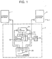
- Fig. 1 is a functional block diagram showing the concept of the present invention.
- terminals and systems for the respective purposes are classified and dispersed into the following three.
- reference numeral 1 denotes an internal network that possesses important data and a system which is made up of a general purpose network connected to a computer system on a communication line.
- the internal network is directed to a system having a terminal or a network which is not connected to the above-mentioned wire or an outer line including wireless.
- reference numeral 2 denotes an external network.
- the external network is directed to a network, a system having the network or a network structural part such as a terminal or a modular jack which is connected to an internet network, a public network, a wire such an exclusive line or an outer line including wireless.
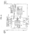
- Reference numeral 3 denotes a control terminal (seesaw type switching security system) for controlling the internal network and the external network, which is the most important element of the present invention.
- the control terminal 3 is made up of a switch server 31, a switch control section 32, a buffer 33, a buffer 34 and a seesaw switching box (SSWB) 35.
- the respective functional sections of those members will be described in more detail later.
- the control terminal 3 has a function of receiving a request from the external network and transmitting the request to the internal network. Also, the control terminal 3 has a function of receiving data of the internal network and transmits the data to the external network.
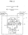
- the seesaw switching box (SSWB) 5 is in a state where the buffer 34 and the buffer 33 are connected to each other in order to transmit the request signal from the external network 2 to the internal network 1.
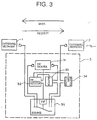
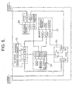
- control terminal 3 has a function of receiving a request from the internal network and transmitting the request to the external network as described in Fig. 3. Also, the control terminal 3 has a function of receiving data of the external network and transmitting the data to the internal network.
- the seesaw switching box (SSWB) 5 is in a state where the internal network 1 and the switch server 31 are connected to each other in order to transmit the request signal from the internal network 1 to the external network 2.
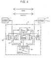
- the control terminal 3 is also capable of transmitting and receiving the request signal and the data signal bidirectionally in both of the internal network 1 and the external network 2 as described in Fig. 4.
- a buffer 37 is interposed between the switch server 31 and the seesaw switching box (SSWB) 35, and a buffer 36 is interposed between the internal network 1 and the seesaw switching box (SSWB) 35 so that the interior of the control terminal 3 is laterally symmetrical with respect to the internal network 1 and the external network 2.
- the buffer 36 holds the request from the internal network until the external side switch (SW2) is closed.
- the buffer 36 has a filtering function of judging whether unjust data exists in the request from the internal network, or not, and discarding the request if the unjust data is detected.
- the buffer 37 has a function of holding the data, which is received from the external network 2 by the switch server 31 and then appropriately processed, until the internal side switch (SW2) is closed.
- control terminal 3 The other operation of the control terminal 3 is identical with that described in the above-mentioned Figs. 2 and 3, and therefore its description will be omitted.
- control terminal 3 The structure that the interior of the control terminal 3 is laterally symmetrical is shown in only Fig. 4. However, such a structure is applicable to even a case where the control terminal 3 is used in any mode.
- the switch server 31 is made up of a computer system which is formed of a bus as a main part, a central processing unit (CPU), a memory, an external memory, an interface (I/O) and so on.
- Program is installed in the external memory, and the central processing unit- (CPU) is so designed as to load the program in the memory and sequentially execute the program, to thereby output the control command signal of the seesaw switching box (SSWB) 35 to the switch control section 32.
- SSWB seesaw switching box
- the switch server 31 conducts processing responsive to the purpose of, for example, requesting necessary data to the internal network in response to the request from the external network, and trying to make the data received from the internal network consistent with the request from the external network. Also, the switch server 31 transmits to the switch control section 32 a control signal for exclusively switching the respective gates (SW1 and SW2) of the external network side and the internal network side on the basis of the request or a signal such as data.
- the switch control section 32 is made up of a plurality of interfaces (I/O) mainly with the central processing unit (CPU) and the memory. In other words, the switching control section 32 is so designed as to control the seesaw switching box (SSWB) 35 on the basis of the control command signal from the switch server 31.
- I/O interfaces
- CPU central processing unit
- SSWB seesaw switching box
- the switch control section 32 is completely out of contact with a data signal path on the network, and monitors the switch server 31, the buffer 34, the buffer 33 and the seesaw switching box (SSWB), respectively, so as to manage the state of the unit.
- SSWB seesaw switching box
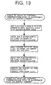
- the switch control section 32 transmits a control signal related to the respective mode changes to the buffers 34 and 33 on the basis of the information from the switch server 31 or the like (refer to Figs. 13 and 14).
- the switch control section 32 transmits the mode state signals of the buffers 34 and 33 to the switch server 31. Also, the switch control section 32 receives a switch change-over control signal from the switch server 31 to the seesaw switching box (SSWB) 35, judges the adequacy with respect to the mode states of the buffers 34 and 33, and transmits the switch change-over control signal to the seesaw switching box (SSWB).
- SSWB seesaw switching box
- the buffers 33 and 34 are substantially identical in structure with each other, but they are different in that the buffer 34 is connected in series to the external network, and in that the buffer 33 is interposed between the seesaw switching box (SSWB) 35 and the switch server 31.
- SSWB seesaw switching box
- the buffer 34 holds the request from the external network until the external side switch (SW2) is closed. Also, the buffer 34 has a filtering function of judging whether unjust data exists in the request from the external network, or not, and discarding the request upon the detection of the unjust data.
- the buffer 33 has a function of holding the data, which is received from the internal network by the switch server 31 and appropriately processed, until the external side switch (SW2) is closed.
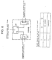
- the seesaws switching box (SSWB) 35 is made up of a flip flop element (FF) and switches (SW1, SW2), and controls any one of those switches 1 and 2 in a short-circuiting state in accordance with the value of a command signal T from the switch control section 32 which is inputted to the flip flop element (FF).
- the seesaw switching box (SSWB) 35 has a function of receiving the control signal from the switch control section 32 and exclusively changing over the switches (SW1 and SW2) at the external network 2 side and the internal network 1 side due to the operation of the flip flop (FF).
- the operation algorithm of the seesaw switching box (SSWB) is described with the truth table in Fig. 6.
- the above-described respective units have the respective distinct roles and are independent from each other and dispersed, thereby being capable of protecting important data fromcracking act or the unjust intrusion.
- the switch control section 32 is completely out of the data signal path on the network, even if the switch server 31 or the buffers 33 and 34 are cracked, such crack is detected, thereby being capable of controlling the seesaw switching box (SSWB).
- a timing at which the switch server 31 outputs the operation mode change-over command (a timing chart in Fig. 15) has the following proposed patterns.
- the above controls (1) to (3) are conducted on the basis of the program installed in the memory of the switch server 1.
- control and monitor mechanism switch control section 32 in this embodiment which is completely out of the data signal path on the network is arranged, and the switch control is conducted, whereby the control from the external due to the cracking is not accepted.
- the timing at which the switch 35 is controlled is not switched by the SWSEC system in the autonomic manner, but the switch server 31 outputs the control instruction, thereby being capable of conducting the switching even if there is no request from the external network 2.
- the request is stored in the buffer 34, and when the connection of the SWSEC system changes over to the external network 2 side, the request is transmitted to the switch server 31 from the buffer 34.
- the connection of the switch server 31 and the external network 2 continues without any interruption, a period of time where the external network 2 is connected to the internal network 1 is periodically provided, and the data to be protected is transmitted to the internal network 1.
- the data to be originated from the switch server 31 during transmission is stored in the buffer 33.
- an information server (not shown) in which information other than the information to be protected is disposed at the external network side, thereby being capable of always receiving the request to the information which may not be protected.
- the request signal is stored in the buffer 34.
- the central processing unit (CPU) within the buffer 34 judges whether the request is unjust or adequate by using filter program installed in the external memory, and if it is unjust, the request is discarded.
- the request is stored in the buffer 34, and waiting is made until it becomes a packet through mode indicating that the switch (SW2) of the seesaw switching box (SSWB) is connected where the internal network 1 and the switch server 31 completes the data communication.
- the switch server 31 When the internal network 1 and the switch server 31 complete the data communication, the switch server 31 outputs to the switch control section 32 a control signal for changing over the connection of the switch of the seesaw switching box (SSWB) 35 from the switch (SW1) to the switch (SW2).
- the switch control section 32 monitors whether the states of the buffer 34 and the buffer 33 is in the packet buffer mode or the packet through mode, and if it is the packet buffer mode, the switch control section 32 sends out a control signal for setting the mode to the packet through mode to the buffers 34 and 33, respectively.
- the switch control section 32 upon receiving the control signal indicative of a notice that the mode was changed to the packet through mode from the buffers 34 and 33, respectively, the switch control section 32 sends out a control signal for changing over the connection of the switch from SW1 to SW2 to the seesaw switching box (SSWB). Also, if it is the packet through mode, the switch control section 32 sends out a control signal for changing over the connection of the switch from SW1 to SW2 to the seesaw switching box (SSWB) 35.
- the above request is inputted to the switch server 31 (switching control and information receiving and originating server) through the switch (SW2) of the seesaw switching box (SSWB) and the buffer 33.
- the central processing unit judges the adequacy and the purpose of the request thus inputted by using filter program, and if the request is unjust, the central processing unit discards the request.
- the central processing units transmits a control signal for changing over the connection of the switch of the seesaw switching box (SSWB) 35 from SW2 to SW1 to the switch control section 32.
- SSWB seesaw switching box
- the switch control section 32 Upon receiving the control signal, the switch control section 32 sends out a control signal for setting the states of the buffer 34 and the buffer 33 to the packet buffer mode to the buffers 34 and 33, respectively. Then, upon receiving a control signal indicative of a notice that the states are changed to the packet buffer mode from the buffers 34 and 33, respectively, the central processing unit sends out a control signal for changing over the connection of the switch from SW2 to SW1 to the seesaw switching box (SSWB) 35.
- SSWB seesaw switching box
- the central processing unit changes over the connection of the switch from SW2 to SW1 due to the operation of the flip flop (FF) (refer to Fig. 8).
- the switch server 31 sends out a request that is suited to the purpose to the internal network 1 side.
- the internal network 1 sends out data in response to the request sent from the switch server 31.
- the data is transmitted to the switch server 31 through the switch (SW1) of the short-circuiting state of the seesaw switching box (SSWB).
- the switch server 31 forms the data in an appropriate format that is suited to the purpose.
- the formation of data is conducted by the central processing unit (CPU) on the basis of the program installed in the external memory.
- the switch server 31 transmits a control signal for changing over the connection of the switch of the seesaw switching box (SSWB) from SW1 to SW2 to the switch control section 32 while sending out the formed data to the buffer 33 which is in the packet buffer mode.
- SSWB seesaw switching box
- the switch control section 32 Upon receiving the control signal from the switch server 31, the switch control section 32 sends out the control signal for changing over the connection of the switch from SW1 to SW2 to the seesaw switching box (SSWB) 35. Subsequently, the switch control section 32 sends out a control signal for setting the state of the buffer 33 to the packet through mode to the buffer 33 and receives a control signal indicative of a notice that the state was changed to the packet through mode from the buffer 33.
- SSWB seesaw switching box
- the buffer 33 Upon completion of transmitting the data, the buffer 33 sends out the notice signal (buffer empty signal) to the switch control section 32. Upon receiving the buffer empty signal, the switch control section 32 sends out a control signal for setting the state to the packet through mode to the buffer 34 that is in the packet buffer mode.
- the notice signal buffer empty signal
- the switch control section 32 Upon receiving the buffer empty signal, the switch control section 32 sends out a control signal for setting the state to the packet through mode to the buffer 34 that is in the packet buffer mode.
- the buffer 34 Upon receiving the control signal, the buffer 34 sets its state to the packet through mode and returns a control signal indicative of a notice that the state was changed to the packet through mode to the switch control section 32.
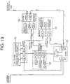
- the external network 2 is connected to the internet 21, and the internet 21 is connected to the web server 1102 of the provider through a rooter 1101.
- the web server 1102 is connected to the internet 22 through the rooter 1103, and the internet 22 is connected with a user terminal 1104.
- the certification results are outputted as data from the internal network 1 on the basis of the certification request from the external network 2, and this operation is realized as described above with reference to Figs. 7 to 10.
- Fig. 12 shows a structure in which the terminal device 21 located within an individual home corresponding to the internal network, transmits a download request of music data to a web server 1203 of the provider, which is the external network, and receives the music data from the web server 1203 in response to that request.
- the terminal device 21 is connected to the internet 1201 through the router and a modular jack 21, and the internet 1201 is connected to the web server 1203 of the provider though the router 1202.
- the music data for music delivery is stored in the web server 1203.
- the transmission of the music data is requested from the individual terminal device 11 to the web server 1203.
- the music data is received by the control terminal 3 from the web server 1203 through the router and the modular jack 21 on the internet 1201.
- "request” and “data” should be changed to "data” and "request”, respectively.
- the present system can be applied to a LAN within an enterprise, a provider, a data center business, a personal PC terminal and so on. That is, the present invention is not limited to the above-described embodiments and their applied examples, but can be applied to any portion on the network and can maintain the internal security for each of network.
Claims (6)
- Un dispositif de contrôle de connexion de commutation (3), pour séparer physiquement un réseau interne (1) et un réseau externe (2), interposé entre ledit réseau externe (2) et ledit réseau interne (1), comprenant :un premier commutateur, pour produire la mise en court-circuit et la connexion du réseau externe (2) ;un deuxième commutateur, pour produire la mise en court-circuit et la déconnexion du réseau interne (1) ;caractérisé en ce qu'il comprend en outre une section de contrôle de commutation (32) placée hors de contact d'un chemin de signal de données connectant le réseau externe (2) et le réseau interne (1), ladite section de contrôle de connexion (32) produisant un signal de commande, pour produire la mise en court-circuit soit dudit premier, soit dudit deuxième commutateur et pour, simultanément, déconnecter l'autre dudit premier et dudit deuxième commutateur, lesdits premier et deuxième commutateurs fonctionnant en un type de bascule, pour produire la mise en court-circuit et la déconnexion du réseau externe (2) et du réseau interne (1), respectivement.
- Le dispositif de contrôle de connexion de commutation (3) tel que revendiqué à la revendication 1, comprenant en outre :un dispositif de contrôle principal (31), pour accomplir une certification et un contrôle de données ;un premier tampon (34), connecté au réseau externe (2) ; etun deuxième tampon (33), connecté audit dispositif de contrôle principal (31), pour stocker une requête ou des données ;dans lequel ledit commutateur est prévu pour produire la mise en court-circuit et la déconnexion dudit premier tampon (34) et dudit deuxième tampon (33) sur le réseau externe (2) ;
ledit deuxième commutateur est prévu pour produire la mise en court-circuit et la déconnexion dudit dispositif de contrôle principal (31) et du réseau interne (1) ; et
ladite section de contrôle de commutation (32) produit le signal de contrôle en fonction du dispositif de contrôle principal (31). - Le dispositif de contrôle de connexion de commutation (3) tel que revendiqué à la revendication 2,
dans lequel ledit premier tampon (34) comprend des moyens de certification, pour vérifier l'exactitude de la requête ou des données venant du réseau externe (2). - Le dispositif de contrôle de connexion de commutation (3) tel que revendiqué à la revendication 2, dans lequel ledit dispositif de contrôle principal (31) comprend des moyens de certification, pour vérifier l'exactitude de la requête ou des données venant du réseau interne (1).
- Le dispositif de contrôle de connexion de commutation (3) tel que revendiqué à la revendication 2, comprenant en outre :un troisième tampon (37), disposé entre ledit dispositif de contrôle principal (31) et ledit deuxième commutateur, pour stocker une requête ou des données ; etun quatrième tampon (36), disposé entre ledit réseau interne (1) et ledit deuxième commutateur, pour stocker une requête ou des données.
- Le dispositif de contrôle de connexion de commutation (3) tel que revendiqué à la revendication 5, dans lequel ledit quatrième tampon (36) comprend des moyens de filtrage, pour apprécier s'il y a présence de données injustes dans la requête issues du réseau interne (1).
Applications Claiming Priority (2)
| Application Number | Priority Date | Filing Date | Title |
|---|---|---|---|
| JP2000182015A JP2002007233A (ja) | 2000-06-16 | 2000-06-16 | 通信路のスイッチ接続制御装置 |
| JP2000182015 | 2000-06-16 |
Publications (3)
| Publication Number | Publication Date |
|---|---|
| EP1164766A2 EP1164766A2 (fr) | 2001-12-19 |
| EP1164766A3 EP1164766A3 (fr) | 2004-06-16 |
| EP1164766B1 true EP1164766B1 (fr) | 2006-02-15 |
Family
ID=18682861
Family Applications (1)
| Application Number | Title | Priority Date | Filing Date |
|---|---|---|---|
| EP01113614A Expired - Lifetime EP1164766B1 (fr) | 2000-06-16 | 2001-06-15 | Dispositif de contrôle de connections de commutation |
Country Status (4)
| Country | Link |
|---|---|
| US (1) | US20010054159A1 (fr) |
| EP (1) | EP1164766B1 (fr) |
| JP (1) | JP2002007233A (fr) |
| DE (1) | DE60117200T2 (fr) |
Cited By (9)
| Publication number | Priority date | Publication date | Assignee | Title |
|---|---|---|---|---|
| US8516033B2 (en) | 1996-11-29 | 2013-08-20 | Frampton E. Ellis, III | Computers or microchips with a hardware side protected by a primary internal hardware firewall leaving an unprotected hardware side connected to a network, and with multiple internal hardware compartments protected by multiple secondary interior hardware firewalls |
| US8555370B2 (en) | 1996-11-29 | 2013-10-08 | Frampton E Ellis | Microchips with an internal hardware firewall |
| US8561164B2 (en) | 1996-11-29 | 2013-10-15 | Frampton E. Ellis, III | Computers and microchips with a side protected by an internal hardware firewall and an unprotected side connected to a network |
| US8627444B2 (en) | 1996-11-29 | 2014-01-07 | Frampton E. Ellis | Computers and microchips with a faraday cage, with a side protected by an internal hardware firewall and unprotected side connected to the internet for network operations, and with internal hardware compartments |
| US8677026B2 (en) | 1996-11-29 | 2014-03-18 | Frampton E. Ellis, III | Computers and microchips with a portion protected by an internal hardware firewalls |
| US8726303B2 (en) | 1996-11-29 | 2014-05-13 | Frampton E. Ellis, III | Microchips with an internal hardware firewall that by its location leaves unprotected microprocessors or processing units which performs processing with a network |
| US8739195B2 (en) | 1996-11-29 | 2014-05-27 | Frampton E. Ellis, III | Microchips with an internal hardware firewall protected portion and a network portion with microprocessors which execute shared processing operations with the network |
| US8898768B2 (en) | 2010-01-26 | 2014-11-25 | Frampton E. Ellis | Computer or microchip with a secure control bus connecting a central controller to volatile RAM and the volatile RAM to a network-connected microprocessor |
| US9568946B2 (en) | 2007-11-21 | 2017-02-14 | Frampton E. Ellis | Microchip with faraday cages and internal flexibility sipes |
Families Citing this family (27)
| Publication number | Priority date | Publication date | Assignee | Title |
|---|---|---|---|---|
| JP3859490B2 (ja) * | 2001-11-13 | 2006-12-20 | 株式会社 イオノス | 通信路のスイッチ接続制御システム |
| JP2003229927A (ja) * | 2002-01-31 | 2003-08-15 | Eastera Kk | ネットワーク接続における情報通信機器の接続制御方法とこれを実施したネットワーク接続制御装置 |
| JP3986871B2 (ja) * | 2002-04-17 | 2007-10-03 | 株式会社エヌ・ティ・ティ・データ | アンチプロファイリング装置およびアンチプロファイリングプログラム |
| US7591001B2 (en) * | 2004-05-14 | 2009-09-15 | Liquidware Labs, Inc. | System, apparatuses, methods and computer-readable media for determining the security status of a computer before establishing a network connection |
| US7549159B2 (en) * | 2004-05-10 | 2009-06-16 | Liquidware Labs, Inc. | System, apparatuses, methods and computer-readable media for determining the security status of a computer before establishing connection thereto |
| US7386889B2 (en) * | 2002-11-18 | 2008-06-10 | Trusted Network Technologies, Inc. | System and method for intrusion prevention in a communications network |
| US7660980B2 (en) * | 2002-11-18 | 2010-02-09 | Liquidware Labs, Inc. | Establishing secure TCP/IP communications using embedded IDs |
| JP2004336619A (ja) * | 2003-05-12 | 2004-11-25 | Sony Corp | 機器間認証システム及び機器間認証方法、通信機器、並びにコンピュータ・プログラム |
| FR2862399B3 (fr) | 2003-11-18 | 2006-01-06 | Sagem | Dispositif de liaison unidirectionnelle dans un reseau ethernet |
| FR2862398A1 (fr) * | 2003-11-18 | 2005-05-20 | Sagem | Dispositif de liaison unidirectionnelle dans un reseau ethernet |
| DE502005005624D1 (de) * | 2005-07-09 | 2008-11-20 | Ads Tec Gmbh | Schutzsystem für eine Datenverarbeitungsanlage |
| FR2895615B1 (fr) * | 2005-12-23 | 2008-04-04 | Cs Systemes D Information Sa | Systeme d'echange de donnees entre deux reseaux de communication de donnees dissocies |
| FR2913155B1 (fr) * | 2007-02-26 | 2009-04-24 | Sagem Defense Securite | Dispositif de connexion selective permettant la connexion d'au moins un peripherique a un ordinateur cible et systeme de controle selectif comportant un tel dispositif |
| FR2917206B1 (fr) * | 2007-06-06 | 2009-12-25 | Airbus France | Systeme embarque de controle d'acces pour une communication du domaine ouvert vers le domaine avionique. |
| FR2936628B1 (fr) * | 2008-09-26 | 2011-04-01 | Vincent Garnier | Plate-forme de reseau informatique |
| US20110225645A1 (en) * | 2010-01-26 | 2011-09-15 | Ellis Frampton E | Basic architecture for secure internet computers |
| WO2011103299A1 (fr) * | 2010-02-17 | 2011-08-25 | Ellis Frampton E | Architecture de base pour ordinateurs sécurisés sur internet |
| US8255986B2 (en) | 2010-01-26 | 2012-08-28 | Frampton E. Ellis | Methods of securely controlling through one or more separate private networks an internet-connected computer having one or more hardware-based inner firewalls or access barriers |
| WO2011094616A1 (fr) * | 2010-01-29 | 2011-08-04 | Ellis Frampton E | Architecture de base pour hôtes internet sécurisés |
| CA2825850A1 (fr) | 2010-01-29 | 2011-08-04 | Frampton E. Ellis | Architecture de base pour hotes internet securises |
| WO2012112794A1 (fr) * | 2011-02-17 | 2012-08-23 | Ellis Frampton E | Procédé d'utilisation d'un réseau privé sécurisé permettant de configurer activement les composants matériels d'un ordinateur ou d'une micro-puce |
| WO2015087216A1 (fr) * | 2013-12-13 | 2015-06-18 | Bombardier Inc. | Appareil et procédés pour assurer la sécurité d'un réseau sur une plate-forme mobile |
| DE102016120769A1 (de) * | 2016-10-31 | 2018-05-03 | HTV Cyperion GmbH | Datenübertragungsvorrichtung, Verfahren zur Übertragung von Daten mit einer Datenübertragungsvorrichtung und Systemanordnung |
| GB2570914B (en) * | 2018-02-09 | 2023-08-16 | Stratford Ken | Secure data storage |
| GB201807503D0 (en) * | 2018-05-08 | 2018-06-20 | Torricel Ltd | Secure data storage, exchange and processing system |
| WO2019243657A1 (fr) * | 2018-06-21 | 2019-12-26 | Wärtsilä Finland Oy | Accès à un réseau informatique sécurisé |
| JP7433624B2 (ja) | 2019-11-29 | 2024-02-20 | 有限会社マック | 遠隔操作システム |
Family Cites Families (4)
| Publication number | Priority date | Publication date | Assignee | Title |
|---|---|---|---|---|
| AU7314096A (en) * | 1995-10-18 | 1997-05-22 | Leslie Christopher Holborow | Computer network security arrangements |
| JP3381055B2 (ja) * | 1997-01-27 | 2003-02-24 | 裕典 若山 | ウィルスの侵入防止方法、及びウィルスの侵入防止機構 |
| CA2320715A1 (fr) * | 1998-02-18 | 1999-08-26 | Lior Netzer | Procede et appareil de securisation des informations |
| US6141755A (en) * | 1998-04-13 | 2000-10-31 | The United States Of America As Represented By The Director Of The National Security Agency | Firewall security apparatus for high-speed circuit switched networks |
-
2000
- 2000-06-16 JP JP2000182015A patent/JP2002007233A/ja active Pending
-
2001
- 2001-06-15 DE DE60117200T patent/DE60117200T2/de not_active Expired - Fee Related
- 2001-06-15 EP EP01113614A patent/EP1164766B1/fr not_active Expired - Lifetime
- 2001-06-18 US US09/881,695 patent/US20010054159A1/en not_active Abandoned
Cited By (16)
| Publication number | Priority date | Publication date | Assignee | Title |
|---|---|---|---|---|
| US9172676B2 (en) | 1996-11-29 | 2015-10-27 | Frampton E. Ellis | Computer or microchip with its system bios protected by one or more internal hardware firewalls |
| US9183410B2 (en) | 1996-11-29 | 2015-11-10 | Frampton E. Ellis | Computer or microchip with an internal hardware firewall and a master controlling device |
| US8561164B2 (en) | 1996-11-29 | 2013-10-15 | Frampton E. Ellis, III | Computers and microchips with a side protected by an internal hardware firewall and an unprotected side connected to a network |
| US8627444B2 (en) | 1996-11-29 | 2014-01-07 | Frampton E. Ellis | Computers and microchips with a faraday cage, with a side protected by an internal hardware firewall and unprotected side connected to the internet for network operations, and with internal hardware compartments |
| US8892627B2 (en) | 1996-11-29 | 2014-11-18 | Frampton E. Ellis | Computers or microchips with a primary internal hardware firewall and with multiple internal harware compartments protected by multiple secondary interior hardware firewalls |
| US8726303B2 (en) | 1996-11-29 | 2014-05-13 | Frampton E. Ellis, III | Microchips with an internal hardware firewall that by its location leaves unprotected microprocessors or processing units which performs processing with a network |
| US8555370B2 (en) | 1996-11-29 | 2013-10-08 | Frampton E Ellis | Microchips with an internal hardware firewall |
| US8739195B2 (en) | 1996-11-29 | 2014-05-27 | Frampton E. Ellis, III | Microchips with an internal hardware firewall protected portion and a network portion with microprocessors which execute shared processing operations with the network |
| US8677026B2 (en) | 1996-11-29 | 2014-03-18 | Frampton E. Ellis, III | Computers and microchips with a portion protected by an internal hardware firewalls |
| US9531671B2 (en) | 1996-11-29 | 2016-12-27 | Frampton E. Ellis | Computer or microchip controlled by a firewall-protected master controlling microprocessor and firmware |
| US9021011B2 (en) | 1996-11-29 | 2015-04-28 | Frampton E. Ellis | Computer or microchip including a network portion with RAM memory erasable by a firewall-protected master controller |
| US8516033B2 (en) | 1996-11-29 | 2013-08-20 | Frampton E. Ellis, III | Computers or microchips with a hardware side protected by a primary internal hardware firewall leaving an unprotected hardware side connected to a network, and with multiple internal hardware compartments protected by multiple secondary interior hardware firewalls |
| US9568946B2 (en) | 2007-11-21 | 2017-02-14 | Frampton E. Ellis | Microchip with faraday cages and internal flexibility sipes |
| US8898768B2 (en) | 2010-01-26 | 2014-11-25 | Frampton E. Ellis | Computer or microchip with a secure control bus connecting a central controller to volatile RAM and the volatile RAM to a network-connected microprocessor |
| US9009809B2 (en) | 2010-01-26 | 2015-04-14 | Frampton E. Ellis | Computer or microchip with a secure system BIOS and a secure control bus connecting a central controller to many network-connected microprocessors and volatile RAM |
| US9003510B2 (en) | 2010-01-26 | 2015-04-07 | Frampton E. Ellis | Computer or microchip with a secure system bios having a separate private network connection to a separate private network |
Also Published As
| Publication number | Publication date |
|---|---|
| US20010054159A1 (en) | 2001-12-20 |
| EP1164766A2 (fr) | 2001-12-19 |
| DE60117200T2 (de) | 2006-11-23 |
| DE60117200D1 (de) | 2006-04-20 |
| EP1164766A3 (fr) | 2004-06-16 |
| JP2002007233A (ja) | 2002-01-11 |
Similar Documents
| Publication | Publication Date | Title |
|---|---|---|
| EP1164766B1 (fr) | Dispositif de contrôle de connections de commutation | |
| RU2178583C2 (ru) | Способ и устройство доступа к ресурсам компьютера через брандмауэр | |
| US20060026292A1 (en) | Data communication method and information processing apparatus for acknowledging signal reception by using low-layer protocol | |
| US20060224897A1 (en) | Access control service and control server | |
| US20040003304A1 (en) | Electronic apparatus and power supply method | |
| KR20060015714A (ko) | 분배 파일 시스템 네트워크에 있어서의 보안성 제공 방법및 시스템 | |
| US20040098621A1 (en) | System and method for selectively isolating a computer from a computer network | |
| US6421317B1 (en) | Method and apparatus for an automatic load balancing and back-up of a multi-users network | |
| US20010056549A1 (en) | Method of providing access control for and/or vis-a-vis users accessing the internet from terminals via a private access node, and arrangements for putting this kind of method into practice | |
| EP0517534A1 (fr) | Répéteur de réseau local | |
| JP2003152806A (ja) | 通信路のスイッチ接続制御システム | |
| JPH02228854A (ja) | データ通信システムおよびデータ通信方法 | |
| JPH10308791A (ja) | データ通信方法、データ通信装置、およびデータ通信プログラム記録媒体 | |
| JP3426832B2 (ja) | ネットワークアクセス制御方法 | |
| KR20180028742A (ko) | 모드 변경이 가능한 양방향 통신 장치 및 방법 | |
| US11936738B2 (en) | System, method, and computer program product for managing a connection between a device and a network | |
| US8375226B1 (en) | System and method for selectively isolating a computer from a computer network | |
| CN105721453A (zh) | 一种网络隔离系统和网络录像机 | |
| JP2701797B2 (ja) | Lan集線装置 | |
| KR20190045892A (ko) | 분리된 망 사이의 데이터 통신을 지원하는 장치 및 그 방법 | |
| WO2001060019A1 (fr) | Systeme de securite informatique | |
| Nessett | A systematic methodology for analyzing security threats to interprocess communication in a distributed system | |
| JP3070213B2 (ja) | 分散型パケット交換機 | |
| WO2020177471A1 (fr) | Procédé de transmission de message, appareil associé et support de stockage | |
| JPS62260449A (ja) | 伝送路を共有する通信装置 |
Legal Events
| Date | Code | Title | Description |
|---|---|---|---|
| PUAI | Public reference made under article 153(3) epc to a published international application that has entered the european phase |
Free format text: ORIGINAL CODE: 0009012 |
|
| AK | Designated contracting states |
Kind code of ref document: A2 Designated state(s): AT BE CH CY DE DK ES FI FR GB GR IE IT LI LU MC NL PT SE TR |
|
| AX | Request for extension of the european patent |
Free format text: AL;LT;LV;MK;RO;SI |
|
| PUAL | Search report despatched |
Free format text: ORIGINAL CODE: 0009013 |
|
| AK | Designated contracting states |
Kind code of ref document: A3 Designated state(s): AT BE CH CY DE DK ES FI FR GB GR IE IT LI LU MC NL PT SE TR |
|
| AX | Request for extension of the european patent |
Extension state: AL LT LV MK RO SI |
|
| 17P | Request for examination filed |
Effective date: 20041111 |
|
| 17Q | First examination report despatched |
Effective date: 20041210 |
|
| AKX | Designation fees paid |
Designated state(s): DE GB |
|
| GRAP | Despatch of communication of intention to grant a patent |
Free format text: ORIGINAL CODE: EPIDOSNIGR1 |
|
| RBV | Designated contracting states (corrected) |
Designated state(s): DE GB |
|
| GRAS | Grant fee paid |
Free format text: ORIGINAL CODE: EPIDOSNIGR3 |
|
| GRAA | (expected) grant |
Free format text: ORIGINAL CODE: 0009210 |
|
| AK | Designated contracting states |
Kind code of ref document: B1 Designated state(s): DE GB |
|
| REG | Reference to a national code |
Ref country code: GB Ref legal event code: FG4D |
|
| REF | Corresponds to: |
Ref document number: 60117200 Country of ref document: DE Date of ref document: 20060420 Kind code of ref document: P |
|
| PLBE | No opposition filed within time limit |
Free format text: ORIGINAL CODE: 0009261 |
|
| STAA | Information on the status of an ep patent application or granted ep patent |
Free format text: STATUS: NO OPPOSITION FILED WITHIN TIME LIMIT |
|
| 26N | No opposition filed |
Effective date: 20061116 |
|
| PGFP | Annual fee paid to national office [announced via postgrant information from national office to epo] |
Ref country code: DE Payment date: 20080626 Year of fee payment: 8 |
|
| PGFP | Annual fee paid to national office [announced via postgrant information from national office to epo] |
Ref country code: GB Payment date: 20080605 Year of fee payment: 8 |
|
| GBPC | Gb: european patent ceased through non-payment of renewal fee |
Effective date: 20090615 |
|
| PG25 | Lapsed in a contracting state [announced via postgrant information from national office to epo] |
Ref country code: GB Free format text: LAPSE BECAUSE OF NON-PAYMENT OF DUE FEES Effective date: 20090615 |
|
| PG25 | Lapsed in a contracting state [announced via postgrant information from national office to epo] |
Ref country code: DE Free format text: LAPSE BECAUSE OF NON-PAYMENT OF DUE FEES Effective date: 20100101 |