EP1164418A2 - Wärmeentwickelbare farbphotographische Elemente, die blockierte Entwickler enthalten - Google Patents
Wärmeentwickelbare farbphotographische Elemente, die blockierte Entwickler enthalten Download PDFInfo
- Publication number
- EP1164418A2 EP1164418A2 EP01202097A EP01202097A EP1164418A2 EP 1164418 A2 EP1164418 A2 EP 1164418A2 EP 01202097 A EP01202097 A EP 01202097A EP 01202097 A EP01202097 A EP 01202097A EP 1164418 A2 EP1164418 A2 EP 1164418A2
- Authority
- EP
- European Patent Office
- Prior art keywords
- group
- substituted
- groups
- image
- aryl
- Prior art date
- Legal status (The legal status is an assumption and is not a legal conclusion. Google has not performed a legal analysis and makes no representation as to the accuracy of the status listed.)
- Withdrawn
Links
- 0 CCC(C)CC(C*CCCC1*CCCC1)=C Chemical compound CCC(C)CC(C*CCCC1*CCCC1)=C 0.000 description 6
- JMCKFKOBZDAVLY-UHFFFAOYSA-N CCN(CC)c(cc1)cc(C)c1N(C)C(OC(CS(C)(=O)=O)C(F)(F)F)=O Chemical compound CCN(CC)c(cc1)cc(C)c1N(C)C(OC(CS(C)(=O)=O)C(F)(F)F)=O JMCKFKOBZDAVLY-UHFFFAOYSA-N 0.000 description 1
- NLVRJWHXLBQZAU-UHFFFAOYSA-N COOc1ccccc1 Chemical compound COOc1ccccc1 NLVRJWHXLBQZAU-UHFFFAOYSA-N 0.000 description 1
Images

Classifications
-
- G—PHYSICS
- G03—PHOTOGRAPHY; CINEMATOGRAPHY; ANALOGOUS TECHNIQUES USING WAVES OTHER THAN OPTICAL WAVES; ELECTROGRAPHY; HOLOGRAPHY
- G03C—PHOTOSENSITIVE MATERIALS FOR PHOTOGRAPHIC PURPOSES; PHOTOGRAPHIC PROCESSES, e.g. CINE, X-RAY, COLOUR, STEREO-PHOTOGRAPHIC PROCESSES; AUXILIARY PROCESSES IN PHOTOGRAPHY
- G03C7/00—Multicolour photographic processes or agents therefor; Regeneration of such processing agents; Photosensitive materials for multicolour processes
- G03C7/30—Colour processes using colour-coupling substances; Materials therefor; Preparing or processing such materials
- G03C7/407—Development processes or agents therefor
- G03C7/413—Developers
-
- G—PHYSICS
- G03—PHOTOGRAPHY; CINEMATOGRAPHY; ANALOGOUS TECHNIQUES USING WAVES OTHER THAN OPTICAL WAVES; ELECTROGRAPHY; HOLOGRAPHY
- G03C—PHOTOSENSITIVE MATERIALS FOR PHOTOGRAPHIC PURPOSES; PHOTOGRAPHIC PROCESSES, e.g. CINE, X-RAY, COLOUR, STEREO-PHOTOGRAPHIC PROCESSES; AUXILIARY PROCESSES IN PHOTOGRAPHY
- G03C1/00—Photosensitive materials
- G03C1/494—Silver salt compositions other than silver halide emulsions; Photothermographic systems ; Thermographic systems using noble metal compounds
- G03C1/498—Photothermographic systems, e.g. dry silver
- G03C1/49836—Additives
- G03C1/49845—Active additives, e.g. toners, stabilisers, sensitisers
-
- G—PHYSICS
- G03—PHOTOGRAPHY; CINEMATOGRAPHY; ANALOGOUS TECHNIQUES USING WAVES OTHER THAN OPTICAL WAVES; ELECTROGRAPHY; HOLOGRAPHY
- G03C—PHOTOSENSITIVE MATERIALS FOR PHOTOGRAPHIC PURPOSES; PHOTOGRAPHIC PROCESSES, e.g. CINE, X-RAY, COLOUR, STEREO-PHOTOGRAPHIC PROCESSES; AUXILIARY PROCESSES IN PHOTOGRAPHY
- G03C8/00—Diffusion transfer processes or agents therefor; Photosensitive materials for such processes
- G03C8/40—Development by heat ; Photo-thermographic processes
- G03C8/4013—Development by heat ; Photo-thermographic processes using photothermographic silver salt systems, e.g. dry silver
- G03C8/408—Additives or processing agents not provided for in groups G03C8/402 - G03C8/4046
-
- G—PHYSICS
- G03—PHOTOGRAPHY; CINEMATOGRAPHY; ANALOGOUS TECHNIQUES USING WAVES OTHER THAN OPTICAL WAVES; ELECTROGRAPHY; HOLOGRAPHY
- G03C—PHOTOSENSITIVE MATERIALS FOR PHOTOGRAPHIC PURPOSES; PHOTOGRAPHIC PROCESSES, e.g. CINE, X-RAY, COLOUR, STEREO-PHOTOGRAPHIC PROCESSES; AUXILIARY PROCESSES IN PHOTOGRAPHY
- G03C7/00—Multicolour photographic processes or agents therefor; Regeneration of such processing agents; Photosensitive materials for multicolour processes
- G03C7/30—Colour processes using colour-coupling substances; Materials therefor; Preparing or processing such materials
- G03C7/305—Substances liberating photographically active agents, e.g. development-inhibiting releasing couplers
- G03C7/30541—Substances liberating photographically active agents, e.g. development-inhibiting releasing couplers characterised by the released group
-
- Y—GENERAL TAGGING OF NEW TECHNOLOGICAL DEVELOPMENTS; GENERAL TAGGING OF CROSS-SECTIONAL TECHNOLOGIES SPANNING OVER SEVERAL SECTIONS OF THE IPC; TECHNICAL SUBJECTS COVERED BY FORMER USPC CROSS-REFERENCE ART COLLECTIONS [XRACs] AND DIGESTS
- Y10—TECHNICAL SUBJECTS COVERED BY FORMER USPC
- Y10S—TECHNICAL SUBJECTS COVERED BY FORMER USPC CROSS-REFERENCE ART COLLECTIONS [XRACs] AND DIGESTS
- Y10S430/00—Radiation imagery chemistry: process, composition, or product thereof
- Y10S430/156—Precursor compound
- Y10S430/16—Blocked developers
Definitions
- This invention relates to color photothermographic elements containing blocked developing agents and to methods of developing such elements.
- films containing light-sensitive silver halide are employed in hand-held cameras. Upon exposure, the film carries a latent image that is only revealed after suitable processing. These elements have historically been processed by treating the camera-exposed film with at least a developing solution having a developing agent that acts to form an image in cooperation with components in the film.
- developing agents commonly used are reducing agents, for example, p -aminophenols or p -phenylenediamines.
- developing agents also herein referred to as developers
- developers present in developer solutions are brought into reactive association with exposed photographic film elements at the time of processing. Segregation of the developer and the film element has been necessary because the incorporation of developers directly into sensitized photographic elements can lead to desensitization of the silver halide emulsion and undesirable fog.
- Considerable effort has been directed to producing effective blocked developing agents (also referred to herein as blocked developers) that might be introduced into silver halide emulsion elements without deleterious desensitization or fog effects. Accordingly, blocked developing agents have been sought that would unblock under preselected conditions of development after which such developing agents would be free to participate in image-forming (dye or silver metal forming) reactions.
- U.S. Pat. No. 3,342,599 to Reeves discloses the use of Schiff-base developer precursors. Schleigh and Faul, in a Research Disclosure (129 (1975) pp. 27-30), describes the quaternary blocking of color developers and the acetamido blocking of p-phenylenediamines. (All Research Disclosures referenced herein are published by Kenneth Mason Publications, Ltd., Dudley Annex, 12a North Street, Emsworth, Hampshire P010 7DQ, ENGLAND.) Subsequently, U.S. Pat. No. 4,157,915 to Hamaoka et al. and U.S. Pat. No. 4, 060,418 to Waxman and Mourning describe the preparation and use of blocked p-phenylenediamines in an image-receiving sheet for color diffusion transfer.
- photothermographic imaging elements that contain a developing agent in a form that is stable until development yet can be rapidly and easily developed once processing has been initiated by heating the element and/or by applying a processing solution, such as a solution of a base or acid or pure water, to the element.
- a processing solution such as a solution of a base or acid or pure water
- a completely dry or apparently dry process is most desirable. The existence of such a process would allow for very rapidly processed films that can be processed simply and efficiently in photoprocessing kiosks. Such kiosks, with increased numbers and accessibility, could ultimately allow for, relatively speaking, anytime and anywhere silver-halide film development.
- This invention relates to a color photothermographic element comprising a blocked developer that decomposes (i.e., unblocks) on thermal activation to release a developing agent.
- thermal activation is meant heating at a temperature of at least 60°C, preferably at least 80°C, more preferably at least 100°C, for 0.5 to 60 sec, preferably 1 to 60 sec, more preferably 2 to 30 sec.
- thermal activation preferably occurs at temperatures between 80 to 180°C, preferably 100 to 160°C.
- thermal activation preferably occurs at temperatures between 60 and 140°C in the presence of added acid, base and/or water.
- the photothermographic element comprises an effective amount of a thermal solvent.
- the photothermographic element comprises a mixture of organic silver salts (inclusive of complexes) at least one of which is a silver donor.
- the invention additionally relates to a method of image formation having the steps of: thermally developing an imagewise exposed photographic element having a blocked developer that decomposes on thermal activation to release a developing agent to form a developed image.
- a positive image can be formed by scanning the developed image to form a first electronic image representation (or "electronic record") from said developed image, digitizing said first electronic record to form a digital image, modifying said digital image to form a second electronic image representation, and storing, transmitting, printing or displaying said second electronic image representation.
- the invention further relates to a one-time use camera having a light sensitive photographic element comprising a support and a blocked developer that decomposes to release a photographically useful group on thermal activation.
- the invention further relates to a method of image formation having the steps of imagewise exposing such a light sensitive photographic element in a one-time-use camera having a heater and thermally processing the exposed element in the camera.
- the present invention is directed to photothermographic elements comprising blocked developers having a half-life (t 1 ⁇ 2 ) ⁇ 20 min (as determined below).
- the specified half-life can be obtained by the use of activating groups in certain positions in the blocking moiety of the blocked developer, as explained more fully below with respect to the specified structures.
- activating groups is herein meant electron withdrawing groups, heteroaromatic groups, or aryl groups substituted with one or more electron withdrawing groups.
- the color photothermographic element of the present invention comprises a blocked developer having a half life of less than or equal to 20 minutes and a peak discrimination, at a temperature of at least 60°C, of at least 2.0, which blocked developer is represented by the following Structure I: wherein:
- the specified half-life can be obtained by the use of activating groups in certain positions in the blocking moiety of the blocked developer of Structure I. More specifically, it has been found that the specified half-life can be obtained by the use of activating groups in the D or X position, with further activation to achieve the specified half-life by the use of activating groups in the one or more of the T and/or W positions in Structure I.
- the activating groups is herein meant electron withdrawing groups, heteroaromatic groups, or aryl groups substituted with one or more electron withdrawing groups.
- the specified half life is obtained by the presence of activating groups, not only at the D or X position, but also at the T and/or W position in Structure I.
- inorganic is herein meant a group not containing carbon excepting carbonates, cyanides, and cyanates.
- heterocyclic herein includes aromatic and non-aromatic rings containing at least one (preferably 1 to 3) heteroatoms in the ring. If the named groups for a symbol such as T in Structure I apparently overlap, the narrower named group is excluded from the broader named group solely to avoid any such apparent overlap.
- heteroaromatic groups in the definition of T may be electron withdrawing in nature, but are not included under monovalent or divalent electron withdrawing groups as they are defined herein.
- activating groups in the D or X position, with further activation as necessary to achieve the necessary half-life by the use of electron withdrawing or heteroaromatic groups in the T and/or W positions in Structure I.
- activating groups is meant electron withdrawing groups, heteroaromatic groups, or aryl groups substituted with one or more electron withdrawing groups.
- activating groups are present, in addition to D or X, in at least one of T or W.
- LINK is of structure II: wherein
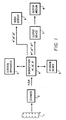
- Fig. 1 shows in block diagram form an apparatus for processing and viewing image formation obtained by scanning the elements of the invention.
- Fig. 2 shows a block diagram showing electronic signal processing of image bearing signals derived from scanning a developed color element according to the invention.
- This invention relates to a photothermographic element comprising blocked developers that decomposes (i.e., unblocks) on thermal activation by a 1,2 elimination mechanism to release a developing agent.
- thermal activation is meant heating at a temperature of at least 60 °C, preferably at least 80 °C, more preferably at least 100 °C, for 0.5 to 60 sec, preferably 1 to 60 sec, more preferably 2 to 30 sec.
- thermal activation preferably occurs at temperatures between 80 to 180 °C, preferably 100 to 160 °C.
- thermal activation preferably occurs at temperatures between 60 and 140 °C in the presence of added acid, base and/or water.
- the invention additionally relates to a method of image formation having the steps of: thermally developing an imagewise exposed photographic element having a blocked developer that decomposes on thermal activation by a 1,2 elimination mechanism to release a developing agent to form a developed image, scanning said developed image to form a first electronic image representation (or "electronic record") from said developed image, digitizing said first electronic record to form a digital image, modifying said digital image to form a second electronic image representation, and storing, transmitting, printing or displaying said second electronic image representation.
- the invention further relates to a one-time use camera having a light sensitive photographic element comprising a support and a blocked developer that decomposes by a 1,2 elimination mechanism to release a photographically useful group on thermal activation.
- the invention further relates to a method of image formation having the steps of imagewise exposing such a light sensitive photographic element in a one-time-use camera having a heater and thermally processing the exposed element in the camera.
- the present invention relates to blocked developers that unblock by means of a 1,2 elimination step involving the separation of the blocked developer into at least three components resulting from the blocking moiety, linking group, and developing agent or a developing agent precursor, for example, involving the separation of a blocked developer into the blocking group with a terminal unsaturation where previously attached to the linking group, carbon dioxide, and the developing agent.
- the present invention is directed to photothermographic elements comprising blocked developers having a half-life (t 1 ⁇ 2 ) ⁇ 20 min (as determined below).
- the specified half-life can be obtained by the use of activating groups in certain positions in the blocking moiety of the blocked developer, as explained more fully below with respect to the specified structures.
- activating groups is herein meant electron withdrawing groups, heteroaromatic groups, or aryl groups substituted with one or more electron withdrawing groups.
- the blocked developer in addition to the specified half life, has superior peak discrimination (Dp) as defined in the examples.
- peak discrimination is meant the maximum difference between Dmin and Dmax as a function of the process temperature, which in turn is defined as the maximum temperature of the photothermographic element during development.
- the Dp is at least 2.0, more preferably at least 3.0, most preferably 4.0 to 10.0.
- the Dp is at a temperature of at least 60°C, preferably 80 to 180°C, more preferably 100 to 160°C with processing time of 0.5 to 60 sec, preferably 1 to 60 sec, more preferably 2 to 30 sec.
- the color photothermographic element of the present invention comprises a blocked developer having a half life of less than or equal to 20 minutes and a peak discrimination, at a temperature of at least 60°C, of at least 2.0, which blocked developer is represented by the following Structure I: wherein:
- the blocked developer is selected from Structure I with the proviso that when t is 0, then D is not -CN or substituted or unsubstituted aryl and X is not -SO 2 - when W is substituted or unsubstituted aryl or alkyl; and when t is not an activating group, then X is not-SO 2 - when W is a substituted or unsubstituted aryl.
- the specified half-life can be obtained by the use of activating groups in certain positions in the blocking moiety of the blocked developer of Structure I. More specifically, it has been found that the specified half-life can be obtained by the use of activating groups in the D or X position. Further activation to achieve the specified half-life may be obtained by the use of activating groups in one or more of the T and/or W positions in Structure I.
- the activating groups is herein meant electron withdrawing groups, heteroaromatic groups, or aryl groups substituted with one or more electron withdrawing groups.
- the specified half life is obtained by the presence of activating groups, in addition to D or X, in at least one of the T or W groups.
- inorganic is herein meant a group not containing carbon excepting carbonates, cyanides, and cyanates.
- heterocyclic herein includes aromatic and non-aromatic rings containing at least one (preferably 1 to 3) heteroatoms in the ring. If the named groups for a symbol such as T in Structure I apparently overlap, the narrower named group is excluded from the broader named group solely to avoid any such apparent overlap.
- heteroaromatic groups in the definition of T may be electron withdrawing in nature, but are not included under monovalent or divalent electron withdrawing groups as they are defined herein.
- activating groups in the D or X position, with further activation as necessary to achieve the necessary half-life by the use of electron withdrawing or heteroaromatic groups in the T and/or W positions in Structure I.
- activating groups is meant electron withdrawing groups, heteroaromatic groups, or aryl groups substituted with one or more electron withdrawing groups.
- T or W is an activating group.
- ⁇ p and ⁇ m parameters which were used first to characterize the ability of benzene ring-substituents (in the para or meta position) to affect the electronic nature of a reaction site, were originally quantified by their effect on the pKa of benzoic acid. Subsequent work has extended and refined the original concept and data, and for the purposes of prediction and correlation, standard sets of ⁇ p and ⁇ m are widely available in the chemical literature, as for example in C. Hansch et al., J. Med. Chem., 17, 1207 (1973).
- the inductive substituent constant ⁇ I is herein used to characterize the electronic property.
- an electron withdrawing group on an aryl ring has a ⁇ p or ⁇ m of greater than zero, more preferably greater than 0.05, most preferably greater than 0.1.
- the ⁇ p is used to define electron withdrawing groups on aryl groups when the substituent is neither para nor meta.
- an electron withdrawing group on a tetrahedral carbon preferably has a ⁇ 1 of greater than zero, more preferably greater than 0.05, and most preferably greater than 0.1.
- Illustrative developing agents that are useful as developers are: wherein
- LINK is of structure II: wherein
- Illustrative linking groups include, for example, or
- TIME is a timing group.
- groups are well-known in the art such as (1) groups utilizing an aromatic nucleophilic substitution reaction as disclosed in US Patent No. 5,262,291; (2) groups utilizing the cleavage reaction of a hemiacetal (US Pat. No. 4,146,396, Japanese Applications 60-249148; 60-249149); (3) groups utilizing an electron transfer reaction along a conjugated system (US Pat. No. 4,409,323; 4,421,845; Japanese Applications 57-188035; 58-98728; 58-209736; 58-209738); and (4) groups using an intramolecular nucleophilic substitution reaction (US Pat. No. 4,248,962).
- timing groups are illustrated by formulae T-1 through T-4. wherein:
- timing groups include, for example: and
- T-2 Specific examples of the group represented by formula (T-2) are illustrated below. and wherein Nu1 represents a nucleophilic group, and an oxygen or sulfur atom can be given as an example of nucleophilic species; E1 represents an electrophilic group being a group which is subjected to nucleophilic attack by Nu1; and LINK4 represents a linking group which enables Nu1 and E1 to have a steric arrangement such that an intramolecular nucleophilic substitution reaction can occur.
- Specific examples of the group represented by formula (T-3) are illustrated below. wherein V, R 13 , R 14 and d all have the same meaning as in formula (T-2), respectively.
- R 13 and R 14 may be joined together to form a benzene ring or a heterocyclic ring, or V may be joined with R 13 or R 14 to form a benzene or heterocyclic ring.
- Z 1 and Z 2 each independently represents a carbon atom or a nitrogen atom, and x and y each represents 0 or 1.
- timing group (T-4) Specific examples of the timing group (T-4) are illustrated below.
- the blocked developers used in the present invention is within Structure I above, but represented by the following narrower Structure III: wherein:
- the present invention includes photothermographic elements comprising blocked developers according to Structure III which blocked developers have a half-life (t 1 ⁇ 2 ) ⁇ 20 min (as determined below).
- the heteroaromatic group is preferably a 5- or 6-membered ring containing one or more hetero atoms, such as N, O, S or Se.
- the heteroaromatic group comprises a substituted or unsubstituted benzimidazolyl, benzothiazolyl, benzoxazolyl, benzothienyl, benzofuryl, furyl, imidazolyl, indazolyl, indolyl, isoquinolyl, isothiazolyl, isoxazolyl, oxazolyl, picolinyl, purinyl, pyranyl, pyrazinyl, pyrazolyl, pyridyl, pyrimidinyl, pyrrolyl, quinaldinyl, quinazolinyl, quinolyl, quinoxalinyl, tetrazolyl, thiadiazolyl, thiatriazolyl,
- 2-imidazolyl 2-benzimidazolyl, 2-thiazolyl, 2-benzothiazolyl, 2-oxazolyl, 2-benzoxazolyl, 2-pyridyl, 2-quinolinyl, 1-isoquinolinyl, 2-pyrrolyl, 2-indolyl, 2-thiophenyl, 2-benzothiophenyl, 2-furyl, 2-benzofuryl, 2-,4-, or 5-pyrimidinyl, 2-pyrazinyl, 3-,4-, or 5-pyrazolyl, 3-indazolyl, 2- and 3-thienyl, 2-(1,3,4-triazolyl), 4-or 5-(1,2,3-triazolyl), 5-(1,2,3,4-tetrazolyl).
- the heterocyclic group may be further substituted.
- Preferred substituents are alkyl and alkoxy groups containing 1 to 6 carbon atoms.
- substituted or unsubstituted means that the moiety may be unsubstituted or substituted with one or more substituents (up to the maximum possible number), for example, substituted or unsubstituted alkyl, substituted or unsubstituted benzene (with up to five substituents), substituted or unsubstituted heteroaromatic (with up to five substituents), and substituted or unsubstituted heterocyclic (with up to five substituents).
- substituent groups usable on molecules herein include any groups, whether substituted or unsubstituted, which do not destroy properties necessary for the photographic utility.
- substituents on any of the mentioned groups can include known substituents, such as: halogen, for example, chloro, fluoro, bromo, iodo; alkoxy, particularly those "lower alkyl" (that is, with 1 to 6 carbon atoms), for example, methoxy, ethoxy; substituted or unsubstituted alkyl, particularly lower alkyl (for example, methyl, trifluoromethyl); thioalkyl (for example, methylthio or ethylthio), particularly either of those with 1 to 6 carbon atoms; substituted and unsubstituted aryl, particularly those having from 6 to 20 carbon atoms (for example, phenyl); and substituted or unsubstituted heteroaryl, particularly those having a 5 or 6-membered ring containing 1 to 3 heteroatoms selected from N, O, or S (for example, pyridyl, thienyl, furyl, pyrrolyl); acid or acid or
- Alkyl substituents may specifically include "lower alkyl” (that is, having 1-6 carbon atoms), for example, methyl, ethyl, and the like. Cycloalkyl when appropriate includes bicycloalkyl. Further, with regard to any alkyl group or alkylene group, it will be understood that these can be branched, unbranched, or cyclic.
- the blocked developer is preferably incorporated in one or more of the imaging layers of the imaging element.
- the amount of blocked developer used is preferably 0.01 to 5g/m 2 , more preferably 0.1 to 2g/m 2 and most preferably 0.3 to 2g/m 2 in each layer to which it is added. These may be color forming or non-color forming layers of the element.
- the blocked developer can be contained in a separate element that is contacted to the photographic element during processing.
- the blocked developer is activated during processing of the imaging element by the presence of acid or base in the processing solution, by heating the imaging element during processing of the imaging element, and/or by placing the imaging element in contact with a separate element, such as a laminate sheet, during processing.
- the laminate sheet optionally contains additional processing chemicals such as those disclosed in Sections XIX and XX of Research Disclosure, September 1996, Number 389, Item 38957 (hereafter referred to as (“ Research Disclosure I "). All sections referred to herein are sections of Research Disclosure I , unless otherwise indicated.
- Such chemicals include, for example, sulfites, hydroxyl amine, hydroxamic acids and the like, antifoggants, such as alkali metal halides, nitrogen containing heterocyclic compounds, and the like, sequestering agents such as an organic acids, and other additives such as buffering agents, sulfonated polystyrene, stain reducing agents, biocides, desilvering agents, stabilizers and the like.
- the blocked compounds may be used in any form of photographic system.
- a typical color negative film construction useful in the practice of the invention is illustrated by the following element, SCN-1: Element SCN-1 SOC Surface Overcoat BU Blue Recording Layer Unit IL1 First Interlayer GU Green Recording Layer Unit IL2 Second Interlayer RU Red Recording Layer Unit AHU Antihalation Layer Unit S Support SOC Surface Overcoat
- the support S can be either reflective or transparent, which is usually preferred. When reflective, the support is white and can take the form of any conventional support currently employed in color print elements. When the support is transparent, it can be colorless or tinted and can take the form of any conventional support currently employed in color negative elements-e.g., a colorless or tinted transparent film support. Details of support construction are well understood in the art. Examples of useful supports are poly(vinylacetal) film, polystyrene film, poly(ethyleneterephthalate) film, poly(ethylene naphthalate) film, polycarbonate film, and related films and resinous materials, as well as paper, cloth, glass, metal, and other supports that withstand the anticipated processing conditions.
- the element can contain additional layers, such as filter layers, interlayers, overcoat layers, subbing layers, antihalation layers and the like. Transparent and reflective support constructions, including subbing layers to enhance adhesion, are disclosed in Section XV of Research Disclosure I.
- Photographic elements of the present invention may also usefully include a magnetic recording material as described in Research Disclosure, Item 34390, November 1992, or a transparent magnetic recording layer such as a layer containing magnetic particles on the underside of a transparent support as in U.S.Patent No. 4,279,945, and U.S.Pat. No. 4,302,523.
- a magnetic recording material as described in Research Disclosure, Item 34390, November 1992
- a transparent magnetic recording layer such as a layer containing magnetic particles on the underside of a transparent support as in U.S.Patent No. 4,279,945, and U.S.Pat. No. 4,302,523.
- Each of blue, green and red recording layer units BU, GU and RU are formed of one or more hydrophilic colloid layers and contain at least one radiation-sensitive silver halide emulsion and coupler, including at least one dye image-forming coupler. It is preferred that the green, and red recording units are subdivided into at least two recording layer sub-units to provide increased recording latitude and reduced image granularity. In the simplest contemplated construction each of the layer units or layer sub-units consists of a single hydrophilic colloid layer containing emulsion and coupler.
- the coupler containing hydrophilic colloid layer is positioned to receive oxidized color developing agent from the emulsion during development.
- the coupler containing layer is the next adjacent hydrophilic colloid layer to the emulsion containing layer.
- all of the sensitized layers are preferably positioned on a common face of the support.
- the element When in spool form, the element will be spooled such that when unspooled in a camera, exposing light strikes all of the sensitized layers before striking the face of the support carrying these layers.
- the total thickness of the layer units above the support should be controlled. Generally, the total thickness of the sensitized layers, interlayers and protective layers on the exposure face of the support are less than 35 ⁇ m.
- any convenient selection from among conventional radiation-sensitive silver halide emulsions can be incorporated within the layer units and used to provide the spectral absorptances of the invention. Most commonly high bromide emulsions containing a minor amount of iodide are employed. To realize higher rates of processing, high chloride emulsions can be employed. Radiation-sensitive silver chloride, silver bromide, silver iodobromide, silver iodochloride, silver chlorobromide, silver bromochloride, silver iodochlorobromide and silver iodobromochloride grains are all contemplated. The grains can be either regular or irregular (e.g., tabular).
- Tabular grain emulsions those in which tabular grains account for at least 50 (preferably at least 70 and optimally at least 90) percent of total grain projected area are particularly advantageous for increasing speed in relation to granularity.
- a grain requires two major parallel faces with a ratio of its equivalent circular diameter (ECD) to its thickness of at least 2.
- ECD equivalent circular diameter
- Specifically preferred tabular grain emulsions are those having a tabular grain average aspect ratio of at least 5 and, optimally, greater than 8.
- Preferred mean tabular grain thicknesses are less than 0.3 ⁇ m (most preferably less than 0.2 ⁇ m).
- Ultrathin tabular grain emulsions those with mean tabular grain thicknesses of less than 0.07 ⁇ m, are specifically contemplated.
- the grains preferably form surface latent images so that they produce negative images when processed in a surface developer in color negative film forms of the invention.
- the dye may be added to an emulsion of the silver halide grains and a hydrophilic colloid at any time prior to (e.g., during or after chemical sensitization) or simultaneous with the coating of the emulsion on a photographic element.
- the dyes may, for example, be added as a solution in water or an alcohol or as a dispersion of solid particles.
- the emulsion layers also typically include one or more antifoggants or stabilizers, which can take any conventional form, as illustrated by section VII. Antifoggants and stabilizers.
- the silver halide grains to be used in the invention may be prepared according to methods known in the art, such as those described in Research Disclosure I, cited above, and James, The Theory of the Photographic Process. These include methods such as ammoniacal emulsion making, neutral or acidic emulsion making, and others known in the art. These methods generally involve mixing a water soluble silver salt with a water soluble halide salt in the presence of a protective colloid, and controlling the temperature, pAg, pH values, etc, at suitable values during formation of the silver halide by precipitation.
- one or more dopants can be introduced to modify grain properties.
- any of the various conventional dopants disclosed in Research Disclosure I, Section I. Emulsion grains and their preparation, subsection G. Grain modifying conditions and adjustments, paragraphs (3), (4) and (5), can be present in the emulsions of the invention.
- a dopant capable of increasing imaging speed by forming a shallow electron trap (hereinafter also referred to as a SET) as discussed in Research Disclosure Item 36736 published November 1994, here incorporated by reference.
- Photographic emulsions generally include a vehicle for coating the emulsion as a layer of a photographic element.
- Useful vehicles include both naturally occurring substances such as proteins, protein derivatives, cellulose derivatives (e.g., cellulose esters), gelatin (e.g., alkali-treated gelatin such as cattle bone or hide gelatin, or acid treated gelatin such as pigskin gelatin), deionized gelatin, gelatin derivatives (e.g., acetylated gelatin, phthalated gelatin, and the like), and others as described in Research Disclosure, I.
- Also useful as vehicles or vehicle extenders are hydrophilic water-permeable colloids.
- polystyrene resin examples include synthetic polymeric peptizers, carriers, and/or binders such as poly(vinyl alcohol), poly(vinyl lactams), acrylamide polymers, polyvinyl acetals, polymers of alkyl and sulfoalkyl acrylates and methacrylates, hydrolyzed polyvinyl acetates, polyamides, polyvinyl pyridine, methacrylamide copolymers.
- the vehicle can be present in the emulsion in any amount useful in photographic emulsions.
- the emulsion can also include any of the addenda known to be useful in photographic emulsions.
- the total quantity be less than 10 g/m 2 of silver.
- Silver quantities of less than 7 g/m 2 are preferred, and silver quantities of less than 5 g/m 2 are even more preferred.
- the lower quantities of silver improve the optics of the elements, thus enabling the production of sharper pictures using the elements.
- These lower quantities of silver are additionally important in that they enable rapid development and desilvering of the elements.
- a silver coating coverage of at least 1.5 g of coated silver per m 2 of support surface area in the element is necessary to realize an exposure latitude of at least 2.7 log E while maintaining an adequately low graininess position for pictures intended to be enlarged.
- BU contains at least one yellow dye image-forming coupler
- GU contains at least one magenta dye image-forming coupler
- RU contains at least one cyan dye image-forming coupler.
- Any convenient combination of conventional dye image-forming couplers can be employed.
- Conventional dye image-forming couplers are illustrated by Research Disclosure I, cited above, X. Dye image formers and modifiers, B. Image-dye-forming couplers.
- the photographic elements may further contain other image-modifying compounds such as "Development Inhibitor-Releasing" compounds (DIR's). Useful additional DIR's for elements of the present invention, are known in the art and examples are described in USPatent Nos.
- DIR compounds are also disclosed in "Developer-Inhibitor-Releasing (DIR) Couplers for Color Photography," C.R. Barr, J.R. Thirtle and P.W. Vittum in Photographic Science and Engineering, Vol. 13, p. 174 (1969), incorporated herein by reference.
- One or more of the layer units of the invention is preferably subdivided into at least two, and more preferably three or more sub-unit layers. It is preferred that all light sensitive silver halide emulsions in the color recording unit have spectral sensitivity in the same region of the visible spectrum. In this embodiment, while all silver halide emulsions incorporated in the unit have spectral absorptance according to invention, it is expected that there are minor differences in spectral absorptance properties between them.
- the sensitizations of the slower silver halide emulsions are specifically tailored to account for the light shielding effects of the faster silver halide emulsions of the layer unit that reside above them, in order to provide an imagewise uniform spectral response by the photographic recording material as exposure varies with low to high light levels.
- higher proportions of peak light absorbing spectral sensitizing dyes may be desirable in the slower emulsions of the subdivided layer unit to account for on-peak shielding and broadening of the underlying layer spectral sensitivity.
- the interlayers IL1 and IL2 are hydrophilic colloid layers having as their primary function color contamination reduction-i.e., prevention of oxidized developing agent from migrating to an adjacent recording layer unit before reacting with dye-forming coupler.
- the interlayers are in part effective simply by increasing the diffusion path length that oxidized developing agent must travel.
- Antistain agents oxidized developing agent scavengers
- a yellow filter such as Carey Lea silver or a yellow processing solution decolorizable dye
- Suitable yellow filter dyes can be selected from among those illustrated by Research Disclosure I, Section VIII. Absorbing and scattering materials, B. Absorbing materials.
- magenta colored filter materials are absent from IL2 and RU.
- the antihalation layer unit AHU typically contains a processing solution removable or decolorizable light absorbing material, such as one or a combination of pigments and dyes. Suitable materials can be selected from among those disclosed in Research Disclosure I, Section VIII. Absorbing materials.
- a common alternative location for AHU is between the support S and the recording layer unit coated nearest the support.
- the surface overcoats SOC are hydrophilic colloid layers that are provided for physical protection of the color negative elements during handling and processing. Each SOC also provides a convenient location for incorporation of addenda that are most effective at or near the surface of the color negative element. In some instances the surface overcoat is divided into a surface layer and an interlayer, the latter functioning as spacer between the addenda in the surface layer and the adjacent recording layer unit. In another common variant form, addenda are distributed between the surface layer and the interlayer, with the latter containing addenda that are compatible with the adjacent recording layer unit. Most typically the SOC contains addenda, such as coating aids, plasticizers and lubricants, antistats and matting agents, such as illustrated by Research Disclosure I, Section IX. Coating physical property modifying addenda.
- the SOC overlying the emulsion layers additionally preferably contains an ultraviolet absorber, such as illustrated by Research Disclosure I, Section VI. UV dyes/optical brighteners/luminescent dyes, paragraph (1).
- layer unit sequence of element SCN-1 instead of the layer unit sequence of element SCN-1, alternative layer units sequences can be employed and are particularly attractive for some emulsion choices.
- high chloride emulsions and/or thin ( ⁇ 0.2 ⁇ m mean grain thickness) tabular grain emulsions all possible interchanges of the positions of BU, GU and RU can be undertaken without risk of blue light contamination of the minus blue records, since these emulsions exhibit negligible native sensitivity in the visible spectrum. For the same reason, it is unnecessary to incorporate blue light absorbers in the interlayers.
- the emulsion layers within a dye image-forming layer unit differ in speed, it is conventional practice to limit the incorporation of dye image-forming coupler in the layer of highest speed to less than a stoichiometric amount, based on silver.
- the function of the highest speed emulsion layer is to create the portion of the characteristic curve just above the minimum density-i.e., in an exposure region that is below the threshold sensitivity of the remaining emulsion layer or layers in the layer unit. In this way, adding the increased granularity of the highest sensitivity speed emulsion layer to the dye image record produced is minimized without sacrificing imaging speed.
- the blue, green and red recording layer units are described as containing yellow, magenta and cyan image dye-forming couplers, respectively, as is conventional practice in color negative elements used for printing.
- the invention can be suitably applied to conventional color negative construction as illustrated.
- Color reversal film construction would take a similar form, with the exception that colored masking couplers would be completely absent; in typical forms, development inhibitor releasing couplers would also be absent.
- the color negative elements are intended exclusively for scanning to produce three separate electronic color records. Thus the actual hue of the image dye produced is of no importance. What is essential is merely that the dye image produced in each of the layer units be differentiable from that produced by each of the remaining layer units.
- each of the layer units contain one or more dye image-forming couplers chosen to produce image dye having an absorption half-peak bandwidth lying in a different spectral region.
- the blue, green or red recording layer unit forms a yellow, magenta or cyan dye having an absorption half peak bandwidth in the blue, green or red region of the spectrum, as is conventional in a color negative element intended for use in printing, or an absorption half-peak bandwidth in any other convenient region of the spectrum, ranging from the near ultraviolet (300-400 nm) through the visible and through the near infrared (700-1200 nm), so long as the absorption half-peak bandwidths of the image dye in the layer units extend over substantially non-coextensive wavelength ranges.
- substantially non-coextensive wavelength ranges means that each image dye exhibits an absorption half-peak band width that extends over at least a 25 (preferably 50) nm spectral region that is not occupied by an absorption half-peak band width of another image dye. Ideally the image dyes exhibit absorption half-peak band widths that are mutually exclusive.
- a layer unit contains two or more emulsion layers differing in speed
- This technique is particularly well suited to elements in which the layer units are divided into sub-units that differ in speed. This allows multiple electronic records to be created for each layer unit, corresponding to the differing dye images formed by the emulsion layers of the same spectral sensitivity.
- the digital record formed by scanning the dye image formed by an emulsion layer of the highest speed is used to recreate the portion of the dye image to be viewed lying just above minimum density.
- second and, optionally, third electronic records can be formed by scanning spectrally differentiated dye images formed by the remaining emulsion layer or layers.
- These digital records contain less noise (lower granularity) and can be used in recreating the image to be viewed over exposure ranges above the threshold exposure level of the slower emulsion layers. This technique for lowering granularity is disclosed in greater detail by Sutton USPatent 5,314,794, the disclosure of which is here incorporated by reference.
- Each layer unit of the color negative elements of the invention produces a dye image characteristic curve gamma of less than 1.5, which facilitates obtaining an exposure latitude of at least 2.7 log E.
- a minimum acceptable exposure latitude of a multicolor photographic element is that which allows accurately recording the most extreme whites (e.g., a bride's wedding gown) and the most extreme blacks (e.g., a bride groom's tuxedo) that are likely to arise in photographic use.
- An exposure latitude of 2.6 log E can just accommodate the typical bride and groom wedding scene.
- An exposure latitude of at least 3.0 log E is preferred, since this allows for a comfortable margin of error in exposure level selection by a photographer.
- any of the conventional incorporated dye image generating compounds employed in multicolor imaging can be alternatively incorporated in the blue, green and red recording layer units.
- Dye images can be produced by the selective destruction, formation or physical removal of dyes as a function of exposure.
- silver dye bleach processes are well known and commercially utilized for forming dye images by the selective destruction of incorporated image dyes. The silver dye bleach process is illustrated by Research Disclosure I, Section X. Dye image formers and modifiers, A. Silver dye bleach.
- pre-formed image dyes can be incorporated in blue, green and red recording layer units, the dyes being chosen to be initially immobile, but capable of releasing the dye chromophore in a mobile moiety as a function of entering into a redox reaction with oxidized developing agent.
- RDR's redox dye releasers
- By washing out the released mobile dyes a retained dye image is created that can be scanned. It is also possible to transfer the released mobile dyes to a receiver, where they are immobilized in a mordant layer. The image-bearing receiver can then be scanned. Initially the receiver is an integral part of the color negative element.
- the receiver When scanning is conducted with the receiver remaining an integral part of the element, the receiver typically contains a transparent support, the dye image bearing mordant layer just beneath the support, and a white reflective layer just beneath the mordant layer.
- the receiver support can be reflective, as is commonly the choice when the dye image is intended to be viewed, or transparent, which allows transmission scanning of the dye image. RDR's as well as dye image transfer systems in which they are incorporated are described in Research Disclosure, Vol. 151, November 1976, Item 15162.
- the dye image can be provided by compounds that are initially mobile, but are rendered immobile during imagewise development.
- Image transfer systems utilizing imaging dyes of this type have long been used in previously disclosed dye image transfer systems. These and other image transfer systems compatible with the practice of the invention are disclosed in Research Disclosure, Vol. 176, December 1978, Item 17643, XXIII. Image transfer systems.
- the imaging element of this invention may be used with non-conventional sensitization schemes.
- the light-sensitive material may have one white-sensitive layer to record scene luminance, and two color-sensitive layers to record scene chrominance.
- the resulting image can be scanned and digitally reprocessed to reconstruct the full colors of the original scene as described in U.S.5,962,205.
- the imaging element may also comprise a pan-sensitized emulsion with accompanying color-separation exposure.
- the developers of the invention would give rise to a colored or neutral image which, in conjunction with the separation exposure, would enable full recovery of the original scene color values.
- the image may be formed by either developed silver density, a combination of one or more conventional couplers, or "black” couplers such as resorcinol couplers.
- the separation exposure may be made either sequentially through appropriate filters, or simultaneously through a system of spatially discreet filter elements (commonly called a "color filter array").
- the imaging element of the invention may also be a black and white image-forming material comprised, for example, of a pan-sensitized silver halide emulsion and a developer of the invention.
- the image may be formed by developed silver density following processing, or by a coupler that generates a dye which can be used to carry the neutral image tone scale.
- Densitometry is the measurement of transmitted light by a sample using selected colored filters to separate the imagewise response of the RGB image dye forming units into relatively independent channels. It is common to use Status M filters to gauge the response of color negative film elements intended for optical printing, and Status A filters for color reversal films intended for direct transmission viewing.
- Image noise can be reduced, where the images are obtained by scanning exposed and processed color negative film elements to obtain a manipulatable electronic record of the image pattern, followed by reconversion of the adjusted electronic record to a viewable form.
- Image sharpness and colorfulness can be increased by designing layer gamma ratios to be within a narrow range while avoiding or minimizing other performance deficiencies, where the color record is placed in an electronic form prior to recreating a color image to be viewed.
- the red, green, and blue light sensitive color forming units each exhibit gamma ratios of less than 1.15. In an even more preferred embodiment, the red and blue light sensitive color forming units each exhibit gamma ratios of less than 1.10. In a most preferred embodiment, the red, green, and blue light sensitive color forming units each exhibit gamma ratios of less than 1.10. In all cases, it is preferred that the individual color unit(s) exhibit gamma ratios of less than 1.15, more preferred that they exhibit gamma ratios of less than 1.10 and even more preferred that they exhibit gamma ratios of less than 1.05. The gamma ratios of the layer units need not be equal.
- Elements having excellent light sensitivity are best employed in the practice of this invention.
- the elements should have a sensitivity of at least ISO 50, preferably have a sensitivity of at least ISO 100, and more preferably have a sensitivity of at least ISO 200. Elements having a sensitivity of up to ISO 3200 or even higher are specifically contemplated.
- the speed, or sensitivity, of a color negative photographic element is inversely related to the exposure required to enable the attainment of a specified density above fog after processing.
- Photographic speed for a color negative element with a gamma of 0.65 in each color record has been specifically defined by the American National Standards Institute (ANSI) as ANSI Standard Number PH 2.27-1981 (ISO (ASA Speed)) and relates specifically the average of exposure levels required to produce a density of 0.15 above the minimum density in each of the green light sensitive and least sensitive color recording unit of a color film.
- This definition conforms to the International Standards Organization (ISO) film speed rating.
- ISO International Standards Organization
- the ASA or ISO speed is to be calculated by linearly amplifying or deamplifying the gamma vs. log E (exposure) curve to a value of 0.65 before determining the speed in the otherwise defined manner.
- the present invention also contemplates the use of photographic elements of the present invention in what are often referred to as single use cameras (or "film with lens” units). These cameras are sold with film preloaded in them and the entire camera is returned to a processor with the exposed film remaining inside the camera.
- the one-time-use cameras employed in this invention can be any of those known in the art. These cameras can provide specific features as known in the art such as shutter means, film winding means, film advance means, waterproof housings, single or multiple lenses, lens selection means, variable aperture, focus or focal length lenses, means for monitoring lighting conditions, means for adjusting shutter times or lens characteristics based on lighting conditions or user provided instructions, and means for camera recording use conditions directly on the film.
- These features include, but are not limited to: providing simplified mechanisms for manually or automatically advancing film and resetting shutters as described at Skarman, USPatent 4,226,517; providing apparatus for automatic exposure control as described at Matterson et al, U S. Patent 4,345,835; moisture-proofing as described at Fujimura et al, USPatent 4,766,451; providing internal and external film casings as described at Ohmura et al, USPatent 4,751,536; providing means for recording use conditions on the film as described at Taniguchi et al, U.S. Patent 4,780,735; providing lens fitted cameras as described at Arai, U.S.
- Patent 4,804,987 providing film supports with superior anti-curl properties as described at Sasaki et al, U.S. Patent 4,827,298; providing a viewfinder as described at Ohmura et al, U.S. Patent 4,812,863; providing a lens of defined focal length and lens speed as described at Ushiro et al, U.S. Patent 4,812,866; providing multiple film containers as described at Nakayama et al, U.S. Patent 4,831,398 and at Ohmura et al, U.S. Patent 4,833,495; providing films with improved anti-friction characteristics as described at Shiba, U.S.
- Patent 4,866,469 providing winding mechanisms, rotating spools, or resilient sleeves as described at Mochida, U.S. Patent 4,884,087; providing a film patrone or cartridge removable in an axial direction as described by Takei et al at U.S. Patents 4,890,130 and 5,063,400; providing an electronic flash means as described at Ohmura et al, U.S. Patent 4,896,178; providing an externally operable member for effecting exposure as described at Mochida et al, U.S. Patent 4,954,857; providing film support with modified sprocket holes and means for advancing said film as described at Murakami, U.S. Patent 5,049,908; providing internal mirrors as described at Hara, U.S. Patent 5,084,719; and providing silver halide emulsions suitable for use on tightly wound spools as described at Yagi et al, European Patent Application 0,466,417 A.
- While the film may be mounted in the one-time-use camera in any manner known in the art, it is especially preferred to mount the film in the one-time-use camera such that it is taken up on exposure by a thrust cartridge.
- Thrust cartridges are disclosed by Kataoka et al U.S. Patent 5,226,613; by Zander U.S. Patent 5,200,777; by Dowling et al U.S. Patent 5,031,852; and by Robertson et al U.S. Patent 4,834,306.
- Narrow bodied one-time-use cameras suitable for employing thrust cartridges in this way are described by Tobioka et al U.S. Patent 5,692,221.
- Cameras may contain a built-in processing capability, for example a heating element. Designs for such cameras including their use in an image capture and display system are disclosed in U.S.Patent Application Serial No. 09/388,573 filed September 1, 1999, incorporated herein by reference. The use of a one-time use camera as disclosed in said application is particularly preferred in the practice of this invention.
- Photographic elements of the present invention are preferably imagewise exposed using any of the known techniques, including those described in Research Disclosure I, Section XVI. This typically involves exposure to light in the visible region of the spectrum, and typically such exposure is of a live image through a lens, although exposure can also be exposure to a stored image (such as a computer stored image) by means of light emitting devices (such as light emitting diodes, CRT and the like).
- a stored image such as a computer stored image
- the photothermographic elements are also exposed by means of various forms of energy, including ultraviolet and infrared regions of the electromagnetic spectrum as well as electron beam and beta radiation, gamma ray, x-ray, alpha particle, neutron radiation and other forms of corpuscular wave-like radiant energy in either non-coherent (random phase) or coherent (in phase) forms produced by lasers. Exposures are monochromatic, orthochromatic, or panchromatic depending upon the spectral sensitization of the photographic silver halide.
- the elements as discussed above may serve as origination material for some or all of the following processes: image scanning to produce an electronic rendition of the capture image, and subsequent digital processing of that rendition to manipulate, store, transmit, output, or display electronically that image.
- the blocked developers of this invention may be used in photographic elements that contain any or all of the features discussed above, but are intended for different forms of processing. These types of systems will be described in detail below.
- Type I Thermal process systems (thermographic and photothermographic), where processing is initiated solely by the application of heat to the imaging element.
- Type II Low volume systems, where film processing is initiated by contact to a processing solution, but where the processing solution volume is comparable to the total volume of the imaging layer to be processed.
- This type of system may include the addition of non solution processing aids, such as the application of heat or of a laminate layer that is applied at the time of processing.
- Types I and II will now be discussed in turn.
- Type I Thermographic and Photothermographic Systems
- the blocked developer is incorporated in a photothermographic element.
- Photothermographic elements of the type described in Research Disclosure 17029 are included by reference.
- the photothermographic elements may be of type A or type B as disclosed in Research Disclosure I.
- Type A elements contain in reactive association a photosensitive silver halide, a reducing agent or developer, an activator, and a coating vehicle or binder. In these systems development occurs by reduction of silver ions in the photosensitive silver halide to metallic silver.
- Type B systems can contain all of the elements of a type A system in addition to a salt or complex of an organic compound with silver ion. In these systems, this organic complex is reduced during development to yield silver metal.
- the organic silver salt will be referred to as the silver donor. References describing such imaging elements include, for example, U.S. Patents 3,457,075; 4,459,350; 4,264,725 and 4,741,992.
- the photothermographic element comprises a photosensitive component that consists essentially of photographic silver halide.
- a photosensitive component that consists essentially of photographic silver halide.
- the latent image silver from the silver halide acts as a catalyst for the described image-forming combination upon processing.
- a preferred concentration of photographic silver halide is within the range of 0.01 to 100 moles of photographic silver halide per mole of silver donor in the photothermographic material.
- the Type B photothermographic element comprises an oxidation-reduction image forming combination that contains an organic silver salt oxidizing agent.
- the organic silver salt is a silver salt which is comparatively stable to light, but aids in the formation of a silver image when heated to 80 °C or higher in the presence of an exposed photocatalyst (i.e., the photosensitive silver halide) and a reducing agent.
- Suitable organic silver salts include silver salts of organic compounds having a carboxyl group. Preferred examples thereof include a silver salt of an aliphatic carboxylic acid and a silver salt of an aromatic carboxylic acid. Preferred examples of the silver salts of aliphatic carboxylic acids include silver behenate, silver stearate, silver oleate, silver laureate, silver caprate, silver myristate, silver palmitate, silver maleate, silver fumarate, silver tartarate, silver furoate, silver linoleate, silver butyrate and silver camphorate, mixtures thereof, etc. Silver salts which are substitutable with a halogen atom or a hydroxyl group can also be effectively used.
- Preferred examples of the silver salts of aromatic carboxylic acid and other carboxyl group-containing compounds include silver benzoate, a silver-substituted benzoate such as silver 3,5-dihydroxybenzoate, silver o-methylbenzoate, silver m-methylbenzoate, silver p-methylbenzoate, silver 2,4-dichlorobenzoate, silver acetamidobenzoate, silver p-phenylbenzoate, etc., silver gallate, silver tannate, silver phthalate, silver terephthalate, silver salicylate, silver phenylacetate, silver pyromellilate, a silver salt of 3-carboxymethyl-4-methyl-4-thiazoline-2-thione or the like as described in U.S. Pat. No. 3,785,830, and silver salt of an aliphatic carboxylic acid containing a thioether group as described in U.S. Pat. No. 3,330,663.
- Silver salts of mercapto or thione substituted compounds having a heterocyclic nucleus containing 5 or 6 ring atoms, at least one of which is nitrogen, with other ring atoms including carbon and up to two hetero-atoms selected from among oxygen, sulfur and nitrogen are specifically contemplated.
- Typical preferred heterocyclic nuclei include triazole, oxazole, thiazole, thiazoline,, imidazoline, imidazole, diazole, pyridine and triazine.
- heterocyclic compounds include a silver salt of 3-mercapto-4-phenyl-1,2,4 triazole, a silver salt of 2-mercaptobenzimidazole, a silver salt of 2-mercapto-5-aminothiadiazole, a silver salt of 2-(2-ethylglycolamido)benzothiazole, a silver salt of 5-carboxylic-1-methyl-2-phenyl-4-thiopyridine, a silver salt of mercaptotriazine, a silver salt of 2-mercaptobenzoxazole, a silver salt as described in U.S. Pat. No.
- a silver salt of 1,2,4-mercaptothiazole derivative such as a silver salt of 3-amino-5-benzylthio-1, 2,4-thiazole
- a silver salt of a thione compound such as a silver salt of 3-(2-carboxyethyl)-4-methyl-4-thiazoline-2-thione as disclosed in U.S. Pat. No. 3,201,678.
- Examples of other useful mercapto or thione substituted compounds that do not contain a heterocyclic nucleus are illustrated by the following: a silver salt of thioglycolic acid such as a silver salt of a S-alkylthioglycolic acid (wherein the alkyl group has from 12 to 22 carbon atoms) as described in Japanese patent application 28221/73, a silver salt of a dithiocarboxylic acid such as a silver salt of dithioacetic acid, and a silver salt of thioamide.
- a silver salt of thioglycolic acid such as a silver salt of a S-alkylthioglycolic acid (wherein the alkyl group has from 12 to 22 carbon atoms) as described in Japanese patent application 28221/73
- a silver salt of a dithiocarboxylic acid such as a silver salt of dithioacetic acid
- thioamide silver salt of thioamide
- a silver salt of a compound containing an imino group can be used.
- Preferred examples of these compounds include a silver salt of benzotriazole and a derivative thereof as described in Japanese patent publications 30270/69 and 18146/70, for example a silver salt of benzotriazole or methylbenzotriazole, etc., a silver salt of a halogen substituted benzotriazole, such as a silver salt of 5-chlorobenzotriazole, etc., a silver salt of 1,2,4-triazole, a silver salt of 3-amino-5-mercaptobenzyl-1,2,4-triazole, of 1H-tetrazole as described in U.S. Pat. No. 4,220,709, a silver salt of imidazole and an imidazole derivative, and the like.
- silver half soap of which an equimolar blend of a silver behenate with behenic acid, prepared by precipitation from aqueous solution of the sodium salt of commercial behenic acid and analyzing 14.5 percent silver
- Transparent sheet materials made on transparent film backing require a transparent coating and for this purpose the silver behenate full soap, containing not more than 4 or 5 percent of free behenic acid and analyzing 25.2 percent silver may be used.
- a method for making silver soap dispersions is well known in the art and is disclosed in Research Disclosure October 1983 (23419) and U.S. Pat. No. 3,985,565.
- Silver salts complexes may also be prepared by mixture of aqueous solutions of a silver ionic species, such as silver nitrate, and a solution of the organic ligand to be complexed with silver.
- the mixture process may take any convenient form, including those employed in the process of silver halide precipitation.
- a stabilizer may be used to avoid flocculation of the silver complex particles.
- the stabilizer may be any of those materials known to be useful in the photographic art, such as, but not limited to, gelatin, polyvinyl alcohol or polymeric or monomeric surfactants.
- the photosensitive silver halide grains and the organic silver salt are coated so that they are in catalytic proximity during development. They can be coated in contiguous layers, but are preferably mixed prior to coating. Conventional mixing techniques are illustrated by Research Disclosure, Item 17029, cited above, as well as U.S. Pat. No. 3,700,458 and published Japanese patent applications Nos. 32928/75, 13224/74, 17216/75 and 42729/76.
- a reducing agent in addition to the blocked developer may be included.
- the reducing agent for the organic silver salt may be any material, preferably organic material, that can reduce silver ion to metallic silver.
- Conventional photographic developers such as 3-pyrazolidinones, hydroquinones, p-aminophenols, p-phenylenediamines and catechol are useful, but hindered phenol reducing agents are preferred.
- the reducing agent is preferably present in a concentration ranging from 5 to 25 percent of the photothermographic layer.
- amidoximes such as phenylamidoxime, 2-thienylamidoxime and p-phenoxy-phenylamidoxime, azines (e.g., 4-hydroxy-3,5-dimethoxybenzaldehydeazine); a combination of aliphatic carboxylic acid aryl hydrazides and ascorbic acid, such as 2,2'-bis(hydroxymethyl)propionylbetaphenyl hydrazide in combination with ascorbic acid; an combination of polyhydroxybenzene and hydroxylamine, a reductone and/or a hydrazine, e.g., a combination of hydroquinone and bis(ethoxyethyl)hydroxylamine, piperidinohexose reductone or formyl-4-methylphenylhydrazine, hydroxamic acids such as phenylhydroxamic acid, p-hydroxyphenyl-hydroxamic acid,
- An optimum concentration of organic reducing agent in the photothermographic element varies depending upon such factors as the particular photothermographic element, desired image, processing conditions, the particular organic silver salt and the particular oxidizing agent.
- the photothermographic element can comprise a thermal solvent.
- thermal solvents for example, salicylanilide, phthalimide, N-hydroxyphthalimide, N-potassium-phthalimide, succinimide, N-hydroxy-1,8-naphthalimide, phthalazine, 1-(2H)-phthalazinone, 2-acetylphthalazinone, benzanilide, and benzenesulfonamide.
- Prior-art thermal solvents are disclosed, for example, in US Pat. No. 6,013,420 to Windender. Examples of toning agents and toning agent combinations are described in, for example, Research Disclosure, June 1978, Item No. 17029 and U.S. Patent No. 4,123,282.
- Post-processing image stabilizers and latent image keeping stabilizers are useful in the photothermographic element. Any of the stabilizers known in the photothermographic art are useful for the described photothermographic element. Illustrative examples of useful stabilizers include photolytically active stabilizers and stabilizer precursors as described in, for example, U.S. Patent 4,459,350. Other examples of useful stabilizers include azole thioethers and blocked azolinethione stabilizer precursors and carbamoyl stabilizer precursors, such as described in U.S. Patent 3,877,940.
- the photothermographic elements preferably contain various colloids and polymers alone or in combination as vehicles and binders and in various layers.
- Useful materials are hydrophilic or hydrophobic. They are transparent or translucent and include both naturally occurring substances, such as gelatin, gelatin derivatives, cellulose derivatives, polysaccharides, such as dextran, gum arabic and the like; and synthetic polymeric substances, such as water-soluble polyvinyl compounds like poly(vinylpyrrolidone) and acrylamide polymers.
- Other synthetic polymeric compounds that are useful include dispersed vinyl compounds such as in latex form and particularly those that increase dimensional stability of photographic elements.
- Effective polymers include water insoluble polymers of acrylates, such as alkylacrylates and methacrylates, acrylic acid, sulfoacrylates, and those that have cross-linking sites.
- Preferred high molecular weight materials and resins include poly(vinyl butyral), cellulose acetate butyrate, poly(methylmethacrylate), poly(vinylpyrrolidone), ethyl cellulose, polystyrene, poly(vinylchloride), chlorinated rubbers, polyisobutylene, butadiene-styrene copolymers, copolymers of vinyl chloride and vinyl acetate, copolymers of vinylidene chloride and vinyl acetate, poly(vinyl alcohol) and polycarbonates.
- organic soluble resins may be coated by direct mixture into the coating formulations.
- any useful organic soluble materials may be incorporated as a latex or other fine particle dispersion.
- Photothermographic elements as described can contain addenda that are known to aid in formation of a useful image.
- the photothermographic element can contain development modifiers that function as speed increasing compounds, sensitizing dyes, hardeners, antistatic agents, plasticizers and lubricants, coating aids, brighteners, absorbing and filter dyes, such as described in Research Disclosure, December 1978, Item No. 17643 and Research Disclosure, June 1978, Item No. 17029.
- the layers of the photothermographic element are coated on a support by coating procedures known in the photographic art, including dip coating, air knife coating, curtain coating or extrusion coating using hoppers. If desired, two or more layers are coated simultaneously.
- a photothermographic element as described preferably comprises a thermal stabilizer to help stabilize the photothermographic element prior to exposure and processing.
- a thermal stabilizer provides improved stability of the photothermographic element during storage.
- Preferred thermal stabilizers are 2-bromo-2-arylsulfonylacetamides, such as 2-bromo-2-p-tolysulfonylacetamide; 2-(tribromomethyl sulfonyl)benzothiazole; and 6-substituted-2,4-bis(tribromomethyl)-s-triazines, such as 6-methyl or 6-phenyl-2,4-bis(tribromomethyl)-s-triazine.
- Imagewise exposure is preferably for a time and intensity sufficient to produce a developable latent image in the photothermographic element.
- the resulting latent image can be developed in a variety of ways.
- the simplest is by overall heating the element to thermal processing temperature.
- This overall heating merely involves heating the photothermographic element to a temperature within the range of 90°C to 180°C until a developed image is formed, such as within 0.5 to 60 seconds.
- a preferred thermal processing temperature is within the range of 100°C to 160°C.
- Heating means known in the photothermographic arts are useful for providing the desired processing temperature for the exposed photothermographic element.
- the heating means is, for example, a simple hot plate, iron, roller, heated drum, microwave heating means, heated air, vapor or the like.
- the design of the processor for the photothermographic element be linked to the design of the cassette or cartridge used for storage and use of the element. Further, data stored on the film or cartridge may be used to modify processing conditions or scanning of the element. Methods for accomplishing these steps in the imaging system are disclosed in commonly assigned, co-pending U.S.Patent Applications Serial Nos. 09/206586, 09/206,612, and 09/206,583 filed December 7, 1998, which are incorporated herein by reference.
- the use of an apparatus whereby the processor can be used to write information onto the element, information which can be used to adjust processing, scanning, and image display is also envisaged. This system is disclosed in U.S.Patent Applications Serial Nos. 09/206,914 filed December 7, 1998 and 09/333,092 filed June 15, 1999, which are incorporated herein by reference.
- Thermal processing is preferably carried out under ambient conditions of pressure and humidity. Conditions outside of normal atmospheric pressure and humidity are useful.
- the components of the photothermographic element can be in any location in the element that provides the desired image. If desired, one or more of the components can be in one or more layers of the element. For example, in some cases, it is desirable to include certain percentages of the reducing agent, toner, stabilizer and/or other addenda in the overcoat layer over the photothermographic image recording layer of the element. This, in some cases, reduces migration of certain addenda in the layers of the element.
- the blocked developer is incorporated in a thermographic element.
- thermographic elements an image is formed by imagewise heating the element.
- the thermal energy source and means for imaging can be any imagewise thermal exposure source and means that are known in the thermographic imaging art.
- the thermographic imaging means can be, for example, an infrared heating means, laser, microwave heating means or the like.
- the retained silver halide can scatter light, decrease sharpness and raise the overall density of the film thus leading to impired scanning. Further, retained silver halide can printout to ambient/viewing/scanning light, render non-imagewise density, degrade signal-to noise of the original scene, and raise density even higher. Finally, the retained silver halide and organic silver salt can remain in reactive association with the other film chemistry, making the film unsuitable as an archival media. Removal or stabilization of these silver sources are necessary to render the PTG film to an archival state.
- the silver coated in the PTG film (silver halide, silver donor, and metallic silver) is unnecessary to the dye image produced, and this silver is valuable and the desire is to recover it is high.
- the silver containing components of the film the silver halide, one or more silver donors, the silver-containing thermal fog inhibitor if present, and/or the silver metal.
- the three main sources are the developed metallic silver, the silver halide, and the silver donor.
- the removal of the silver halide and silver donor can be accomplished with a common fixing chemical as known in the photographic arts.
- useful chemicals include: thioethers, thioureas, thiols, thiones, thionamides, amines, quaternary amine salts, ureas, thiosulfates, thiocyanates, bisulfites, amine oxides, iminodiethanol -sulfur dioxide addition complexex, amphoteric amines, bis-sulfonylmethanes, and the carbocyclic and heterocyclic derivatives of these compounds.
- These chemicals have the ability to form a soluble complex with silver ion and transport the silver out of the film into a receiving vehicle.
- the receiving vehicle can be another coated layer (laminate) or a conventional liquid processing bath.
- the stabilization of the silver halide and silver donor can also be accomplished with a common stabilization chemical.
- the previously mentioned silver salt removal compounds can be employed in this regard.
- the silver is not necessarily removed from the film, although the fixing agent and stabilization agents could very well be a single chemical.
- the physical state of the stabilized silver is no longer in large (> 50 nm) particles as it was for the silver halide and silver donor, so the stabilized state is also advantaged in that light scatter and overall density is lower, rendering the image more suitable for scanning.
- the removal of the metallic silver is more difficult than removal of the silver halide and silver donor.
- two reaction steps are involved.
- the first step is to bleach the metallic silver to silver ion.
- the second step may be identical to the removal/stabilization step(s) described for silver halide and silver donor above.
- Metallic silver is a stable state that does not compromise the archival stability of the PTG film. Therefore, if stabilization of the PTG film is favored over removal of silver, the bleach step can be skipped and the metallic silver left in the film. In cases where the metallic silver is removed, the bleach and fix steps can be done together (called a blix) or sequentially (bleach + fix).
- the process could involve one or more of the scenarios or permutaions of steps.
- the steps can be done one right after another or can be delayed with respect to time and location.
- heat development and scanning can be done in a remote kiosk, then bleaching and fixing accomplished several days later at a retail photofinishing lab.
- multiple scanning of images is accomplished. For example, an initial scan may be done for soft display or a lower cost hard display of the image after heat processing, then a higher quality or a higher cost secondary scan after stabilization is accomplished for archiving and printing, optionally based on a selection from the initial display.
- Type II processing this refers to low volume processing (“substantially dry” or “apparently dry”) which is defined as phtotothermographic processing where the volume of applied developer solution is between 0.1 to 10 times, preferably 0.5 to 10 times, the volume of solution required to swell the photographic element. This processing may take place by a combination of solution application, external layer lamination, and heating.
- the low volume processing system may contain any of the elements described above for Type I: Photothermographic systems.
- any components described in the preceding sections that are not necessary for the formation or stability of latent image in the origination film element can be removed from the film element altogether and contacted at any time after exposure for the purpose of carrying out photographic processing, using the methods described below.
- the Type II photographic element may receive some or all of the following treatments:
- this electronic signal is further manipulated to form a useful electronic record of the image.
- the electrical signal can be passed through an analog-to-digital converter and sent to a digital computer together with location information required for pixel (point) location within the image.
- this electronic signal is encoded with colorimetric or tonal information to form an electronic record that is suitable to allow reconstruction of the image into viewable forms such as computer monitor displayed images, television images, printed images, and so forth.
- imaging elements of this invention will be scanned prior to the removal of silver halide from the element.
- the remaining silver halide yields a turbid coating, and it is found that improved scanned image quality for such a system can be obtained by the use of scanners that employ diffuse illumination optics.
- Any technique known in the art for producing diffuse illumination can be used.
- Preferred systems include reflective systems, that employ a diffusing cavity whose interior walls are specifically designed to produce a high degree of diffuse reflection, and transmissive systems, where diffusion of a beam of specular light is accomplished by the use of an optical element placed in the beam that serves to scatter light.
- Such elements can be either glass or plastic that either incorporate a component that produces the desired scattering, or have been given a surface treatment to promote the desired scattering.
- a conventional technique for minimizing the impact of aberrant pixel signals is to adjust each pixel density reading to a weighted average value by factoring in readings from adjacent pixels, closer adjacent pixels being weighted more heavily.
- the elements of the invention can have density calibration patches derived from one or more patch areas on a portion of unexposed photographic recording material that was subjected to reference exposures, as described by Wheeler et al U.S.Patent 5,649,260, Koeng at al U.S.Patent 5,563,717, and by Cosgrove et al U.S.Patent 5,644,647.
- Patent 5,065,255 Osamu et al U.S. Patent 5,051,842; Lee et al U.S. Patent 5,012,333; Bowers et al U.S. Patent 5,107,346; Telle U.S. Patent 5,105,266; MacDonald et al U.S. Patent 5,105,469; and Kwon et al U.S. Patent 5,081,692.
- Techniques for color balance adjustments during scanning are disclosed by Moore et al U.S. Patent 5,049,984 and Davis U.S. Patent 5,541,645.
- the digital color records once acquired are in most instances adjusted to produce a pleasingly color balanced image for viewing and to preserve the color fidelity of the image bearing signals through various transformations or renderings for outputting, either on a video monitor or when printed as a conventional color print.
- Preferred techniques for transforming image bearing signals after scanning are disclosed by Giorgianni et al U.S. Patent 5,267,030, the disclosures of which are herein incorporated by reference. Further illustrations of the capability of those skilled in the art to manage color digital image information are provided by Giorgianni and Madden Digital Color Management, Addison-Wesley, 1998.
- Fig. 1 shows, in block diagram form, the manner in which the image information provided by the color negative elements of the invention is contemplated to be used.
- An image scanner 2 is used to scan by transmission an imagewise exposed and photographically processed color negative element 1 according to the invention.
- the scanning beam is most conveniently a beam of white light that is split after passage through the layer units and passed through filters to create separate image records-red recording layer unit image record (R), green recording layer unit image record (G), and blue recording layer unit image record (B).
- RGB recording layer unit image record
- G green recording layer unit image record
- B blue recording layer unit image record
- blue, green, and red filters can be sequentially caused to intersect the beam at each pixel location.
- separate blue, green, and red light beams as produced by a collection of light emitting diodes, can be directed at each pixel location.
- an array detector such as an array charge-coupled device (CCD)
- a linear array detector such as a linear array CCD
- Signal intensity and location information is fed to a workstation 4, and the information is transformed into an electronic form R', G', and B', which can be stored in any convenient storage device 5.
- a common approach is to transfer the color negative film information into a video signal using a telecine transfer device.
- Two types of telecine transfer devices are most common: (1) a flying spot scanner using photomultiplier tube detectors or (2) CCD's as sensors. These devices transform the scanning beam that has passed through the color negative film at each pixel location into a voltage. The signal processing then inverts the electrical signal in order to render a positive image. The signal is then amplified and modulated and fed into a cathode ray tube monitor to display the image or recorded onto magnetic tape for storage.
- a video monitor 6 which receives the digital image information modified for its requirements, indicated by R", G", and B", allows viewing of the image information received by the workstation. Instead of relying on a cathode ray tube of a video monitor, a liquid crystal display panel or any other convenient electronic image viewing device can be substituted.
- the video monitor typically relies upon a picture control apparatus 3, which can include a keyboard and cursor, enabling the workstation operator to provide image manipulation commands for modifying the video image displayed and any image to be recreated from the digital image information.
- the modified image information R''', G''', and B''' can be sent to an output device 7 to produce a recreated image for viewing.
- the output device can be any convenient conventional element writer, such as a thermal dye transfer, inkjet, electrostatic, electrophotographic, electrostatic, thermal dye sublimation or other type of printer. CRT or LED printing to sensitized photographic paper is also contemplated.
- the output device can be used to control the exposure of a conventional silver halide color paper.
- the output device creates an output medium 8 that bears the recreated image for viewing.
- the image in the output medium that is ultimately viewed and judged by the end user for noise (granularity), sharpness, contrast, and color balance.
- the image on a video display may also ultimately be viewed and judged by the end user for noise, sharpness, tone scale, color balance, and color reproduction, as in the case of images transmitted between parties on the World Wide Web of the Internet computer network.
- the images contained in color negative elements in accordance with the invention are converted to digital form, manipulated, and recreated in a viewable form.
- Color negative recording materials according to the invention can be used with any of the suitable methods described in U.S. Patent 5,257,030.
- Giorgianni et al provides for a method and means to convert the R, G, and B image-bearing signals from a transmission scanner to an image manipulation and/or storage metric which corresponds to the trichromatic signals of a reference image-producing device such as a film or paper writer, thermal printer, video display, etc.
- the metric values correspond to those which would be required to appropriately reproduce the color image on that device.
- the reference image producing device was chosen to be a specific video display, and the intermediary image data metric was chosen to be the R', G', and B' intensity modulating signals (code values) for that reference video display
- the R, G, and B image-bearing signals from a scanner would be transformed to the R', G', and B' code values corresponding to those which would be required to appropriately reproduce the input image on the reference video display.
- a data-set is generated from which the mathematical transformations to convert R, G, and B image-bearing signals to the aforementioned code values are derived.
- Exposure patterns chosen to adequately sample and cover the useful exposure range of the film being calibrated, are created by exposing a pattern generator and are fed to an exposing apparatus.
- the exposing apparatus produces trichromatic exposures on film to create test images consisting of approximately 150 color patches.
- Test images may be created using a variety of methods appropriate for the application. These methods include: using exposing apparatus such as a sensitometer, using the output device of a color imaging apparatus, recording images of test objects of known reflectances illuminated by known light sources, or calculating trichromatic exposure values using methods known in the photographic art. If input films of different speeds are used, the overall red, green, and blue exposures must be properly adjusted for each film in order to compensate for the relative speed differences among the films. Each film thus receives equivalent exposures, appropriate for its red, green, and blue speeds. The exposed film is processed chemically.
- Film color patches are read by transmission scanner which produces R, G, and B image-bearing signals corresponding each color patch.
- Signal-value patterns of code value pattern generator produces RGB intensity-modulating signals which are fed to the reference video display.
- the R', G', and B' code values for each test color are adjusted such that a color matching apparatus, which may correspond to an instrument or a human observer, indicates that the video display test colors match the positive film test colors or the colors of a printed negative.
- a transform apparatus creates a transform relating the R, G, and B image-bearing signal values for the film's test colors to the R', G', and B' code values of the corresponding test colors.
- the mathematical operations required to transform R, G, and B image-bearing signals to the intermediary data may consist of a sequence of matrix operations and look-up tables (LUT's).
- input image-bearing signals R, G, and B are transformed to intermediary data values corresponding to the R', G', and B' output image-bearing signals required to appropriately reproduce the color image on the reference output device as follows:
- look-up tables are typically provided for each input color.
- three 1-dimensional look-up tables can be employed, one for each of a red, green, and blue color record.
- a multi-dimensional look-up table can be employed as described by D'Errico at U.S. 4,941,039.
- the output image-bearing signals for the reference output device of step 4 above may be in the form of device-dependent code values or the output image-bearing signals may require further adjustment to become device specific code values. Such adjustment may be accomplished by further matrix transformation or 1-dimensional look-up table transformation, or a combination of such transformations to properly prepare the output image-bearing signals for any of the steps of transmitting, storing, printing, or displaying them using the specified device.
- the R, G, and B image-bearing signals from a transmission scanner are converted to an image manipulation and/or storage metric which corresponds to a measurement or description of a single reference image-recording device and/or medium and in which the metric values for all input media correspond to the trichromatic values which would have been formed by the reference device or medium had it captured the original scene under the same conditions under which the input media captured that scene.
- the reference image recording medium was chosen to be a specific color negative film, and the intermediary image data metric was chosen to be the measured RGB densities of that reference film, then for an input color negative film according to the invention, the R, G, and B image-bearing signals from a scanner would be transformed to the R', G', and B' density values corresponding to those of an image which would have been formed by the reference color negative film had it been exposed under the same conditions under which the color negative recording material according to the invention was exposed.
- Exposure patterns chosen to adequately sample and cover the useful exposure range of the film being calibrated, are created by exposing a pattern generator and are fed to an exposing apparatus.
- the exposing apparatus produces trichromatic exposures on film to create test images consisting of approximately 150 color patches.
- Test images may be created using a variety of methods appropriate for the application. These methods include: using exposing apparatus such as a sensitometer, using the output device of a color imaging apparatus, recording images of test objects of known reflectances illuminated by known light sources, or calculating trichromatic exposure values using methods known in the photographic art. If input films of different speeds are used, the overall red, green, and blue exposures must be properly adjusted for each film in order to compensate for the relative speed differences among the films.
- Each film thus receives equivalent exposures, appropriate for its red, green, and blue speeds.
- the exposed film is processed chemically.
- Film color patches are read by a transmission scanner which produces R, G, and B image-bearing signals corresponding each color patch and by a transmission densitometer which produces R', G', and B' density values corresponding to each patch.
- a transform apparatus creates a transform relating the R, G, and B image-bearing signal values for the film's test colors to the measured R', G', and B' densities of the corresponding test colors of the reference color negative film.
- the reference image recording medium was chosen to be a specific color negative film
- the intermediary image data metric was chosen to be the predetermined R', G', and B' intermediary densities of step 2 of that reference film
- the R, G, and B image-bearing signals from a scanner would be transformed to the R', G', and B' intermediary density values corresponding to those of an image which would have been formed by the reference color negative film had it been exposed under the same conditions under which the color negative recording material according to the invention was exposed.
- each input film calibrated according to the present method would yield, insofar as possible, identical intermediary data values corresponding to the R', G', and B' code values required to appropriately reproduce the color image which would have been formed by the reference color negative film on the reference output device.
- Uncalibrated films may also be used with transformations derived for similar types of films, and the results would be similar to those described.
- the mathematical operations required to transform R, G, and B image-bearing signals to the intermediary data metric of this preferred embodiment may consist of a sequence of matrix operations and 1-dimensional LUTs. Three tables are typically provided for the three input colors. It is appreciated that such transformations can also be accomplished in other embodiments by employing a single mathematical operation or a combination of mathematical operations in the computational steps produced by the host computer including, but not limited to, matrix algebra, algebraic expressions dependent on one or more of the image-bearing signals, and n-dimensional LUTs.
- matrix 1 of step 2 is a 3x3 matrix. In a more preferred embodiment, matrix 1 of step 2 is a 3x10 matrix.
- the 1-dimensional LUT 3 in step 4 transforms the intermediary image-bearing signals according to a color photographic paper characteristic curve, thereby reproducing normal color print image tone scale.
- LUT 3 of step 4 transforms the intermediary image-bearing signals according to a modified viewing tone scale that is more pleasing, such as possessing lower image contrast.
- the image processing is not limited to the specific manipulations described above. While the image is in this form, additional image manipulation may be used including, but not limited to, standard scene balance algorithms (to determine corrections for density and color balance based on the densities of one or more areas within the negative), tone scale manipulations to amplify film underexposure gamma, non-adaptive or adaptive sharpening via convolution or unsharp masking, red-eye reduction, and non-adaptive or adaptive grain-suppression. Moreover, the image may be artistically manipulated, zoomed, cropped, and combined with additional images or other manipulations known in the art.
- the image may be electronically transmitted to a remote location or locally written to a variety of output devices including, but not limited to, silver halide film or paper writers, thermal printers, electrophotographic printers, ink-jet printers, display monitors, CD disks, optical and magnetic electronic signal storage devices, and other types of storage and display devices as known in the art.
- output devices including, but not limited to, silver halide film or paper writers, thermal printers, electrophotographic printers, ink-jet printers, display monitors, CD disks, optical and magnetic electronic signal storage devices, and other types of storage and display devices as known in the art.
- the luminance and chrominance sensitization and image extraction article and method described by Arakawa et al in U. S. Patent 5,962,205 can be employed.
- the disclosures of Arakawa et al are incorporated by reference.
- TBDMSC1 Solid tert -butyldimethylsilyl chloride (TBDMSC1, 18.09 g, 120 mmol) was added in one portion to a solution of 14 (19.24 g, 100 mmol) and imidazole (9.55 g, 140 mmol) in 250 mL of tetrahydrofuran, stirred under nitrogen. After 2 h at room temperature the mixture was quenched with 200 mL of saturated aqueous sodium bicarbonate and extracted with ether. The crude product was filtered through silica gel (ether/heptane) giving 29.21 g (95 mmol, 95%) of 15.
- a stirred reaction vessel was charged with 431 g of lime processed gelatin and 6569 g of distilled water.
- a solution containing 214 g of benzotriazole, 2150 g of distilled water, and 790 g of 2.5 molar sodium hydroxide was prepared (Solution B).
- the mixture in the reaction vessel was adjusted to a pAg of 7.25 and a pH of 8.00 by additions of Solution B, nitric acid, and sodium hydroxide as needed.
- a 4 L solution of 0.54 molar silver nitrate was added to the kettle at 250 cc/minute, and the pAg was maintained at 7.25 by a simultaneous addition of solution B. This process was continued until the silver nitrate solution was exhausted, at which point the mixture was concentrated by ultrafiltration.
- the resulting silver salt dispersion contained fine particles of silver benzotriazole.
- Emulsion E-1 is a first Emulsion E-1:
- a silver halide tabular emulsion with a composition of 97% silver bromide and 3% silver iodide was prepared by conventional means.
- the resulting emulsion had an equivalent circular diameter of 0.6 microns and a thickness of 0.09 microns.
- This emulsion was spectrally sensitized to blue light by addition of ] Dye 1 and then chemically sensitized for optimum performance.
- Coupler Dispersion CDM-1 Coupler Dispersion CDM-1: .
- An oil based coupler dispersion was prepared containing coupler M-1 and tricresyl phosphate at a weight ratio of 1:0.5.
- the resulting coatings were exposed through a step wedge to a 3.04 log lux light source at 3000K filtered by Daylight 5A and Wratten 2B filters. The exposure time was 1 second. After exposure, the coating was thermally processed by contact with a heated platen for 20 seconds. A number of strips were processed at a variety of platen temperatures in order to yield an optimum strip process condition. From these data, two parameters were obtained:
- the coatings of this example were prepared using the coating formulation listed in Table 1-1 above.
- the resulting coatings were exposed through a step wedge to a 3.04 log lux light source at 3000K filtered by Daylight 5A and Wratten 2B filters. The exposure time was 1 second.
- the coatings were thermally processed by contact with a heated platen for 20 seconds. A number of strips were processed at a variety of platen temperatures in order to yield an optimum strip process condition. From this data, the parameters T o and D p as described in example 1 were obtained.
- the performance of coatings in this example is shown in table 2-1.
- inventive developers offer peak discriminations similar to those or improved over those of the comparative materials.
- the resulting coatings were exposed through a step wedge to a 3.04 log lux light source at 3000K filtered by Daylight 5A and Wratten 2B filters. The exposure time was 1 second. After exposure, the coatings were thermally processed by contact with a heated platen for 20 seconds. A number of strips were processed at a variety of platen temperatures in order to yield an optimum strip process condition. From this data, the parameter T o as described in example 1 was obtained. The performance of coatings in this example is shown in table 3-2.
- Table 3-1 shows that the inventive developers show reductions in onset temperature which are desirable.
- This Example illustrates the method of determining the half life ( t 1 ⁇ 2 ) or thermal activity of the blocked developers according to the present invention. Except for blocked developers in which a heteroaromatic D group is present (see below), the blocked developers are test for thermal activity as follows: The blocked developer was dissolved at a concentration of ⁇ 1.6 x 10 -5 M in a solution consisting of 33% (v/v) EtOH in deionized water at 60 °C and pH 7.87 and ionic strength 0.125 in the presence of Coupler-1 (224PG, 0.0004 M) and K 3 Fe(CN) 6 (0.00036 M).
- the inventive blocked compounds that show half-lives of 30 min or less.
- the half-lives are 25 min or less, more preferably 20 min or less.
Landscapes
- Physics & Mathematics (AREA)
- General Physics & Mathematics (AREA)
- Chemical & Material Sciences (AREA)
- Engineering & Computer Science (AREA)
- Materials Engineering (AREA)
- Non-Silver Salt Photosensitive Materials And Non-Silver Salt Photography (AREA)
- Nitrogen Condensed Heterocyclic Rings (AREA)
- Pyridine Compounds (AREA)
- Organic Low-Molecular-Weight Compounds And Preparation Thereof (AREA)
- Indole Compounds (AREA)
Applications Claiming Priority (2)
| Application Number | Priority Date | Filing Date | Title |
|---|---|---|---|
| US21130400P | 2000-06-13 | 2000-06-13 | |
| US211304P | 2000-06-13 |
Publications (2)
| Publication Number | Publication Date |
|---|---|
| EP1164418A2 true EP1164418A2 (de) | 2001-12-19 |
| EP1164418A3 EP1164418A3 (de) | 2002-11-27 |
Family
ID=22786348
Family Applications (1)
| Application Number | Title | Priority Date | Filing Date |
|---|---|---|---|
| EP01202097A Withdrawn EP1164418A3 (de) | 2000-06-13 | 2001-06-01 | Wärmeentwickelbare farbphotographische Elemente, die blockierte Entwickler enthalten |
Country Status (8)
| Country | Link |
|---|---|
| US (1) | US6537712B1 (de) |
| EP (1) | EP1164418A3 (de) |
| JP (1) | JP2002072408A (de) |
| KR (1) | KR20010112106A (de) |
| CN (1) | CN1329281A (de) |
| BR (1) | BR0102394A (de) |
| CA (1) | CA2345195A1 (de) |
| HK (1) | HK1043406A1 (de) |
Cited By (1)
| Publication number | Priority date | Publication date | Assignee | Title |
|---|---|---|---|---|
| EP1217430A3 (de) * | 2000-11-30 | 2003-11-19 | Fuji Photo Film Co., Ltd. | Bilderzeugungsverfahren und System |
Families Citing this family (2)
| Publication number | Priority date | Publication date | Assignee | Title |
|---|---|---|---|---|
| JP5224016B2 (ja) * | 2006-03-10 | 2013-07-03 | 晃二 有光 | 感活性エネルギー線塩基発生剤、感活性エネルギー線塩基発生剤組成物、塩基反応性組成物及びパターン形成方法 |
| US8077192B2 (en) * | 2008-01-07 | 2011-12-13 | Zink Imaging, Inc. | Platen temperature model |
Family Cites Families (14)
| Publication number | Priority date | Publication date | Assignee | Title |
|---|---|---|---|---|
| USB342599I5 (de) | 1965-06-07 | |||
| US4060418A (en) | 1976-02-13 | 1977-11-29 | Gaf Corporation | Phenoxy carbonyl derivatives of a paraphenylenediamine color developer and their use in an image-receiving sheet for color diffusion transfer |
| JPS5814671B2 (ja) | 1977-05-02 | 1983-03-22 | 富士写真フイルム株式会社 | カラ−写真感光材料 |
| JPS5776543A (en) | 1980-10-30 | 1982-05-13 | Konishiroku Photo Ind Co Ltd | Photographic sensitive silver halide material |
| JPS5814672A (ja) | 1981-07-17 | 1983-01-27 | Matsushita Graphic Commun Syst Inc | 画像読取装置 |
| JPS62131253A (ja) | 1985-12-03 | 1987-06-13 | Fuji Photo Film Co Ltd | 画像形成方法 |
| JPS62131255A (ja) * | 1985-12-03 | 1987-06-13 | Fuji Photo Film Co Ltd | 画像形成方法 |
| JPH083616B2 (ja) | 1986-11-13 | 1996-01-17 | 富士写真フイルム株式会社 | カラ−画像形成方法 |
| JPH0769596B2 (ja) | 1988-08-17 | 1995-07-31 | 富士写真フイルム株式会社 | 熱現像カラー感光材料 |
| US5019492A (en) | 1989-04-26 | 1991-05-28 | Eastman Kodak Company | Photographic element and process comprising a blocked photographically useful compound |
| US5358843A (en) | 1993-08-20 | 1994-10-25 | Minnesota Mining And Manufacturing Company | Photothermographic elements containing silyl blocking groups |
| EP0800114B1 (de) * | 1996-03-11 | 2003-11-05 | Fuji Photo Film Co., Ltd. | Bilderzeugungsverfahren und System |
| DE19843057A1 (de) | 1998-09-19 | 2000-03-23 | Agfa Gevaert Ag | Farbfotografisches Material |
| US6426179B1 (en) | 1999-12-30 | 2002-07-30 | Eastman Kodak Company | Imaging element containing a blocked photographically useful compound |
-
2000
- 2000-11-09 US US09/710,348 patent/US6537712B1/en not_active Expired - Fee Related
-
2001
- 2001-04-25 CA CA002345195A patent/CA2345195A1/en not_active Abandoned
- 2001-06-01 EP EP01202097A patent/EP1164418A3/de not_active Withdrawn
- 2001-06-12 JP JP2001176866A patent/JP2002072408A/ja not_active Withdrawn
- 2001-06-12 BR BR0102394-2A patent/BR0102394A/pt not_active Application Discontinuation
- 2001-06-13 CN CN01121287A patent/CN1329281A/zh active Pending
- 2001-06-13 KR KR1020010033299A patent/KR20010112106A/ko not_active Withdrawn
-
2002
- 2002-06-19 HK HK02104573.5A patent/HK1043406A1/zh unknown
Cited By (1)
| Publication number | Priority date | Publication date | Assignee | Title |
|---|---|---|---|---|
| EP1217430A3 (de) * | 2000-11-30 | 2003-11-19 | Fuji Photo Film Co., Ltd. | Bilderzeugungsverfahren und System |
Also Published As
| Publication number | Publication date |
|---|---|
| US6537712B1 (en) | 2003-03-25 |
| CA2345195A1 (en) | 2001-12-13 |
| JP2002072408A (ja) | 2002-03-12 |
| HK1043406A1 (zh) | 2002-09-13 |
| EP1164418A3 (de) | 2002-11-27 |
| KR20010112106A (ko) | 2001-12-20 |
| CN1329281A (zh) | 2002-01-02 |
| BR0102394A (pt) | 2002-02-19 |
Similar Documents
| Publication | Publication Date | Title |
|---|---|---|
| US6790569B2 (en) | Color photothermographic elements comprising phenolic thermal solvents | |
| US7414146B2 (en) | Imaging element containing a blocked photographically useful compound | |
| US20020018967A1 (en) | Processing system for a color photothermographic film comprising dry thermal development and wet-chemical remediation | |
| US6306551B1 (en) | Imaging element containing a blocked photographically useful compound | |
| US6312879B1 (en) | Photographic or photothermographic element containing a blocked photographically useful compound | |
| US6521384B2 (en) | Silver-halide-containing photothermographic element for improved scanning | |
| US20020018944A1 (en) | Processing of color photothermographic film comprising dry thermal development and wet-chemical remediation | |
| US6413708B1 (en) | Imaging element containing a blocked photographically useful compound | |
| US6426179B1 (en) | Imaging element containing a blocked photographically useful compound | |
| EP1113316A2 (de) | Bildaufzeichnungselement, das eine in der Photographie anwendbare blockierte Verbindung enthält | |
| US6506546B1 (en) | Imaging element containing a blocked photographically useful compound | |
| US6440618B1 (en) | Imaging element containing a blocked photographically useful compound | |
| US6537712B1 (en) | Color photothermographic elements comprising blocked developing agents | |
| US6506528B1 (en) | Photothermographic element containing a mixture of blocked developers | |
| WO2001096947A2 (en) | Processing of color photohermographic element comprising dry thermal development and wet chemical further processing | |
| US6759187B1 (en) | Imaging element containing a blocked photographically useful compound | |
| US6534226B1 (en) | Imaging element containing a blocked photographically useful compound | |
| US7112398B2 (en) | Imaging element containing a blocked photographically useful compound | |
| US6749977B1 (en) | Imaging element containing a polymeric heteroaromatic blocked developer | |
| US20020160283A1 (en) | Silver-halide-containing photothermographic element for improved scanning | |
| EP1321806A2 (de) | Bildaufzeichnungselement, das eine blockierte photographisch nützliche Verbindung enthält, die durch Azolsulfonyl-unterstützte 1,2-Eliminierung aktiviert wird |
Legal Events
| Date | Code | Title | Description |
|---|---|---|---|
| PUAI | Public reference made under article 153(3) epc to a published international application that has entered the european phase |
Free format text: ORIGINAL CODE: 0009012 |
|
| AK | Designated contracting states |
Kind code of ref document: A2 Designated state(s): AT BE CH CY DE DK ES FI FR GB GR IE IT LI LU MC NL PT SE TR |
|
| AX | Request for extension of the european patent |
Free format text: AL;LT;LV;MK;RO;SI |
|
| PUAL | Search report despatched |
Free format text: ORIGINAL CODE: 0009013 |
|
| AK | Designated contracting states |
Kind code of ref document: A3 Designated state(s): AT BE CH CY DE DK ES FI FR GB GR IE IT LI LU MC NL PT SE TR |
|
| AX | Request for extension of the european patent |
Free format text: AL;LT;LV;MK;RO;SI |
|
| RIC1 | Information provided on ipc code assigned before grant |
Free format text: 7G 03C 1/498 A, 7G 03C 8/40 B |
|
| 17P | Request for examination filed |
Effective date: 20030502 |
|
| AKX | Designation fees paid |
Designated state(s): BE CH IT LI NL |
|
| REG | Reference to a national code |
Ref country code: DE Ref legal event code: 8566 |
|
| 17Q | First examination report despatched |
Effective date: 20040402 |
|
| STAA | Information on the status of an ep patent application or granted ep patent |
Free format text: STATUS: THE APPLICATION IS DEEMED TO BE WITHDRAWN |
|
| 18D | Application deemed to be withdrawn |
Effective date: 20041013 |