EP1164345A1 - Heat exchanger - Google Patents
Heat exchanger Download PDFInfo
- Publication number
- EP1164345A1 EP1164345A1 EP00981693A EP00981693A EP1164345A1 EP 1164345 A1 EP1164345 A1 EP 1164345A1 EP 00981693 A EP00981693 A EP 00981693A EP 00981693 A EP00981693 A EP 00981693A EP 1164345 A1 EP1164345 A1 EP 1164345A1
- Authority
- EP
- European Patent Office
- Prior art keywords
- heat exchanger
- portions
- protrusion
- protrusion portions
- fins
- Prior art date
- Legal status (The legal status is an assumption and is not a legal conclusion. Google has not performed a legal analysis and makes no representation as to the accuracy of the status listed.)
- Granted
Links
Images





Classifications
-
- F—MECHANICAL ENGINEERING; LIGHTING; HEATING; WEAPONS; BLASTING
- F28—HEAT EXCHANGE IN GENERAL
- F28F—DETAILS OF HEAT-EXCHANGE AND HEAT-TRANSFER APPARATUS, OF GENERAL APPLICATION
- F28F1/00—Tubular elements; Assemblies of tubular elements
- F28F1/10—Tubular elements and assemblies thereof with means for increasing heat-transfer area, e.g. with fins, with projections, with recesses
- F28F1/12—Tubular elements and assemblies thereof with means for increasing heat-transfer area, e.g. with fins, with projections, with recesses the means being only outside the tubular element
- F28F1/24—Tubular elements and assemblies thereof with means for increasing heat-transfer area, e.g. with fins, with projections, with recesses the means being only outside the tubular element and extending transversely
- F28F1/32—Tubular elements and assemblies thereof with means for increasing heat-transfer area, e.g. with fins, with projections, with recesses the means being only outside the tubular element and extending transversely the means having portions engaging further tubular elements
-
- F—MECHANICAL ENGINEERING; LIGHTING; HEATING; WEAPONS; BLASTING
- F28—HEAT EXCHANGE IN GENERAL
- F28F—DETAILS OF HEAT-EXCHANGE AND HEAT-TRANSFER APPARATUS, OF GENERAL APPLICATION
- F28F1/00—Tubular elements; Assemblies of tubular elements
- F28F1/10—Tubular elements and assemblies thereof with means for increasing heat-transfer area, e.g. with fins, with projections, with recesses
- F28F1/12—Tubular elements and assemblies thereof with means for increasing heat-transfer area, e.g. with fins, with projections, with recesses the means being only outside the tubular element
- F28F1/126—Tubular elements and assemblies thereof with means for increasing heat-transfer area, e.g. with fins, with projections, with recesses the means being only outside the tubular element consisting of zig-zag shaped fins
- F28F1/128—Fins with openings, e.g. louvered fins
-
- F—MECHANICAL ENGINEERING; LIGHTING; HEATING; WEAPONS; BLASTING
- F28—HEAT EXCHANGE IN GENERAL
- F28D—HEAT-EXCHANGE APPARATUS, NOT PROVIDED FOR IN ANOTHER SUBCLASS, IN WHICH THE HEAT-EXCHANGE MEDIA DO NOT COME INTO DIRECT CONTACT
- F28D1/00—Heat-exchange apparatus having stationary conduit assemblies for one heat-exchange medium only, the media being in contact with different sides of the conduit wall, in which the other heat-exchange medium is a large body of fluid, e.g. domestic or motor car radiators
- F28D1/02—Heat-exchange apparatus having stationary conduit assemblies for one heat-exchange medium only, the media being in contact with different sides of the conduit wall, in which the other heat-exchange medium is a large body of fluid, e.g. domestic or motor car radiators with heat-exchange conduits immersed in the body of fluid
- F28D1/04—Heat-exchange apparatus having stationary conduit assemblies for one heat-exchange medium only, the media being in contact with different sides of the conduit wall, in which the other heat-exchange medium is a large body of fluid, e.g. domestic or motor car radiators with heat-exchange conduits immersed in the body of fluid with tubular conduits
- F28D1/0408—Multi-circuit heat exchangers, e.g. integrating different heat exchange sections in the same unit or heat exchangers for more than two fluids
- F28D1/0426—Multi-circuit heat exchangers, e.g. integrating different heat exchange sections in the same unit or heat exchangers for more than two fluids with units having particular arrangement relative to the large body of fluid, e.g. with interleaved units or with adjacent heat exchange units in common air flow or with units extending at an angle to each other or with units arranged around a central element
- F28D1/0435—Combination of units extending one behind the other
-
- F—MECHANICAL ENGINEERING; LIGHTING; HEATING; WEAPONS; BLASTING
- F28—HEAT EXCHANGE IN GENERAL
- F28D—HEAT-EXCHANGE APPARATUS, NOT PROVIDED FOR IN ANOTHER SUBCLASS, IN WHICH THE HEAT-EXCHANGE MEDIA DO NOT COME INTO DIRECT CONTACT
- F28D21/00—Heat-exchange apparatus not covered by any of the groups F28D1/00 - F28D20/00
- F28D2021/0019—Other heat exchangers for particular applications; Heat exchange systems not otherwise provided for
- F28D2021/008—Other heat exchangers for particular applications; Heat exchange systems not otherwise provided for for vehicles
- F28D2021/0084—Condensers
-
- F—MECHANICAL ENGINEERING; LIGHTING; HEATING; WEAPONS; BLASTING
- F28—HEAT EXCHANGE IN GENERAL
- F28D—HEAT-EXCHANGE APPARATUS, NOT PROVIDED FOR IN ANOTHER SUBCLASS, IN WHICH THE HEAT-EXCHANGE MEDIA DO NOT COME INTO DIRECT CONTACT
- F28D21/00—Heat-exchange apparatus not covered by any of the groups F28D1/00 - F28D20/00
- F28D2021/0019—Other heat exchangers for particular applications; Heat exchange systems not otherwise provided for
- F28D2021/008—Other heat exchangers for particular applications; Heat exchange systems not otherwise provided for for vehicles
- F28D2021/0091—Radiators
- F28D2021/0094—Radiators for recooling the engine coolant
-
- F—MECHANICAL ENGINEERING; LIGHTING; HEATING; WEAPONS; BLASTING
- F28—HEAT EXCHANGE IN GENERAL
- F28F—DETAILS OF HEAT-EXCHANGE AND HEAT-TRANSFER APPARATUS, OF GENERAL APPLICATION
- F28F9/00—Casings; Header boxes; Auxiliary supports for elements; Auxiliary members within casings
- F28F9/001—Casings in the form of plate-like arrangements; Frames enclosing a heat exchange core
- F28F2009/004—Common frame elements for multiple cores
-
- F—MECHANICAL ENGINEERING; LIGHTING; HEATING; WEAPONS; BLASTING
- F28—HEAT EXCHANGE IN GENERAL
- F28F—DETAILS OF HEAT-EXCHANGE AND HEAT-TRANSFER APPARATUS, OF GENERAL APPLICATION
- F28F2215/00—Fins
- F28F2215/02—Arrangements of fins common to different heat exchange sections, the fins being in contact with different heat exchange media
Definitions
- the present invention relates to a heat exchanger, particularly to a duplex heat exchanger in which a radiator and a condenser for a vehicle are integrated.
- the cooling fins of the heat exchanger have a protrusion portion protruded from an end of the tube in the width direction of the tube to the direction perpendicular to the longitudinal direction of the tubes to increase the radiation area, thus improving the radiation ability of the heat exchanger.
- the width direction of the tube is a direction perpendicular to the longitudinal direction of the tube.
- the louvers on the cooling fin are formed in louver board style by cutting and setting up part of the fin, and disturb the airflow around the fin to suppress growth of the temperature boundary layer, thereby improving the heat transfer coefficient between the airflow and the fin.
- the louvers disturb the airflow, the resistance to the airflow passing through the heat exchanger may be increased.
- the louver is formed by cutting and setting up part of the fin, the thermal conductive area of the fin extending to the end of the protrusion portion is decreased, and thereby a sufficient amount of heat may not be conducted from the tube to the fin, and the improvement in radiation ability appropriate to the increase in radiation area may, accordingly, not be achieved.
- a heat exchanger comprises a plurality of tubes (111, 121) in which fluid flows and which extend to the direction perpendicular to the direction of airflow, and fins (112, 122) which are provided on the outer surface of the tubes (111, 121) to accelerate the heat exchange between air and the fluid, wherein the fins (112, 122) have protrusion portions (112e, 122e) protruded from an end of the tubes (111, 121) in the width direction of the tube to the direction perpendicular to the longitudinal direction of the tubes (111, 121), and uneven portions (112f, 122f) are formed on the protrusion portions (112e, 122e), without cutting part of them, to increase the surface area of the fins (112, 122).
- the surface area of the protrusion portions (112e, 122e) may be increased without decreasing the thermal conductive area extending to the end of the protrusion portions (112e, 122e), and thereby a sufficient amount of heat may be conducted from the tubes (111, 121) to the fins (112, 122), especially to the protrusion portions (112e, 122e), and the improvement of radiation ability appropriate to the increase of radiation area may be achieved accordingly.
- the uneven portions (112f, 122f) do not disturb the airflow as much as the louvers because the uneven portions are not formed by cutting part of the fins in contrast to the louvers, thus decreasing the airflow resistance more than the louver.
- the heat transfer coefficient of the protrusion portions (112e, 122e) may be lower than that in case that the louvers are provided, the surface area of the protrusion portions (112e, 122e) are increased without decreasing the thermal conductive area of the protrusion portions (112e, 122e), and the air volume is increased due to the decrease of airflow resistance, and thereby the radiation ability may be improved,
- Another embodiment of the present invention comprises a plurality of tubes (111, 121) in which fluid flows and which extend to the direction perpendicular to the direction of airflow, and fins (112, 122) which are provided on the outer surface of the tubes (111, 121) to accelerate the heat exchange between air and the fluid, and on which louvers (112d, 122d) are formed in louver board style by cutting and setting up part of the fins (112, 122), wherein the fins (112, 122) have protrusion portions (112e, 122e) protruded from an end of the tubes (111, 121) in the width direction of the tube to the direction perpendicular to the longitudinal direction of the tubes (111, 121), and the louvers (112d, 122d) formed on the protrusion portions (112e, 122e) are different from the louvers (112d, 122d) formed on the other portions than the protrusion portions (112e, 122e) of the fins (112, 122).
- the airflow resistance of the protrusion portions may be decreased, and the improvement in radiation ability appropriate to the increase of radiation area may be achieved accordingly.
- the heat exchanger of another embodiment of the present invention is a duplex heat exchanger comprising a first heat exchanger (110) which is a heat exchanger according to the present invention, and a second heat exchanger (120) which is a heat exchanger according to the present invention arranged in series with the first heat exchanger (110) in the direction of airflow, wherein the protrusion portions (112e) of the first heat exchanger (110) are protruded to the second heat exchanger (120), and the protrusion portions (122e) of the second heat exchanger (120) are protruded to the first heat exchanger (110).
- the first embodiment relates to a duplex heat exchanger, which is a heat exchanger according to the present invention, in which a condenser (radiator, condenser) for a refrigeration cycle system (air conditioner) for a vehicle, and a radiator for cooling the cooling water (cooling liquid) for a water-cooled engine (liquid-cooled internal combustion engine).
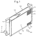
- Fig.1 is a perspective view of the duplex heat exchanger 100 of the first embodiment viewed from the upstream side of the airflow.
- Fig.2 is a perspective view from the water-cooled engine side (downstream side of the airflow).
- the condenser and the radiator are arranged in series in the direction of airflow so that the condenser is positioned on the upstream side of the radiator.
- reference numeral 110 denotes a condenser (first heat exchanger) for conducting heat-exchange between the refrigerant circulating in the refrigeration cycle system and air to cool the refrigerant.
- the condenser 110 comprises a plurality of condenser tubes 111 in which the refrigerant (first fluid) flows, condenser fins (first fins) 112 which are provided on the outer surface between each two condenser tubes 111 to accelerate the heat exchange between the refrigerant and the air, header tanks 113 and 114 which are arranged at the both ends in the longitudinal direction of the condenser tubes 111 and are connected to the condenser tubes 111, etc.
- the header tank 113 at the right side in the figure supplies and distributes the refrigerant to each condenser tube 111, and the header tank 114 at the left side in the figure collects the refrigerant after heat exchanging in each condenser tube 111.
- the condenser tubes 111 are of a multi-hole structure in which many refrigerant paths 111a are formed, and are formed flat in the manner of extrusion work or drawing work, as shown in Fig.4A.
- the condenser fins 112 are integrated with the after-mentioned radiator fins 122, and the details are discussed later.
- radiator 120 denotes a radiator for conducting heat-exchange between the cooling water flowing out from the water-cooled engine and air to cool the cooling water.
- the radiator 120 comprises a plurality of radiator tubes 121 in which cooling water (second fluid) flows, radiator fins (second fins) 122 which are provided between each two condenser tubes 111 to accelerate the heat exchange between the cooling water and air, header tanks 123 and 124 which are arranged at the both ends in the longitudinal direction of the radiator tubes 121 and are connected to each radiator tube 121, etc.
- the reference numeral 130 denotes a side-plate which is arranged at the end of the condenser 110 and the radiator 120 to reinforce both of the condenser 110 and the radiator 120.
- the tubes 111 and 121, the fins 112 and 122, the header tanks 113, 114, 123, and 124, and the side-plates 130 are integrated by soldering.
- the fins 112, 122 are discussed below.
- the fins 112, 122 are formed in a single piece by a roller forming method as shown in Fig.3, and are wave form corrugated fins consisting of a plurality of crest portions 112a, 122a, trough portions 112b, 122b, and flat portions 112c, 122c which connect adjacent crest portions 112a, 122a, and trough portions 112b, 122b.
- louvers 112d, 122d are formed in louver board style by cutting and setting up part of the flat portions 112c, 122c to disturb the airflow passing through the fins 112, 122 to prevent growth of a temperature boundary layer.
- connecting portions f are provided at intervals of a plurality of crest portions to connect the fins 112 and 122 so as to keep a distance of more than predetermined length W between the condenser fin 112 and the radiator fin 122.
- the predetermined length W is at least more than the thickness of the fin 112 or 122, and a slit (space) S which is provided by keeping a distance of more than predetermined length W between the condenser fin 112 and the radiator fin 122 functions as a heat transfer suppressing means for suppressing the heat transfer from the radiator 120 side to the condenser 110 side.
- a protrusion portion 112e is provided which protrudes from an end of the condenser tube 111 in the width direction of the tube to the radiator tube 121, in the direction perpendicular to the longitudinal direction of the condenser tube 111.
- a protrusion portion 122e is provided which protrudes from an end of the radiator tube 121 in the width direction of the tube to the condenser tube 111, in the direction perpendicular to the longitudinal direction of the radiator tube 121.
- uneven portions 112f, 122f are formed in wave form in the manner of plastic deformation by a roller forming machine without cutting part of the protrusion portions 112e, 122e to increase the surface area of the fins 112, 122.
- the uneven portions 112f, 122f are also formed so that the ridge direction Dw of the uneven portions 112f, 122f is substantially parallel with a cutting direction Dr of the louvers 112d, 122d.
- the ridge direction Dw of the protrusion portions 112f, 122f is the direction ranging the summits of the crest portions 112g, 122g (see Fig.4B) of the wave form uneven portions 112f, 122f, and the cutting direction Dr of the louvers 112d, 122d is the direction substantially perpendicular to the ridge direction Df ranging the summits of the crest portions 112a, 122a of the fins 112, 122.
- the uneven portions 112f, 122f are provided on the protrusion portions 112e, 122e without cutting part of the protrusion portions 112e, 122e, and thereby the surface area of the protrusion portions 112e, 122e may be increased without decreasing the thermal conductive area of the fins extending to the end of the protrusion portions 112e, 122e.
- a sufficient amount of heat may be conducted from the tubes 111, 121 to the fins 112, 122 (especially to the protrusion portions 112e, 122e), and the improvement in radiation ability appropriate to the increase in radiation area may be achieved accordingly.
- the uneven portions 112f, 122f do not disturb the airflow as much as the louver 112d, 122d because the uneven portion 112f, 122f are not formed by cutting part of the fins in contrast to the louvers 112d, 122d, thereby decreasing the airflow resistance more than the louvers.
- the heat transfer coefficient of the protrusion portions 112e, 122e may be lower than that of the other portions (flat portions 112c, 122c) or the protrusion portion 112e, 122e, on which the louvers 112d, 122d are provided, the surface area of the protrusion portions 112e, 122e is increased without decreasing the thermal conductive area of the protrusion portions 112e, 122e, and the air volume is increased due to the decrease of airflow resistance, and thereby the radiation ability may be improved.
- the uneven portions 112f, 122f are also formed so that the ridge direction Dw of the uneven portions 112f, 122f is substantially parallel with a cutting direction Dr of the louvers 112d, 122d, the ridge direction Dw and the cutting direction Dr are both substantially perpendicular to the fin material moving direction of the roller forming machine, and thereby the uneven portions 112f and 122f, and the louvers 112d and 122d may be formed without using a special roller forming machine. For this reason, productivity of the fins 112 and 122 may be improved, and production cost of the fins 112 and 122 (the duplex heat exchanger 100) may be reduced accordingly.
- the uneven portions 112f and 122f are formed in a wave form, but in this embodiment, the uneven portions 112f and 122f are formed with dice-formed unevenness (dimples) as shown in Fig.6.
- the uneven portions 112f, 122f are formed on the protrusion portions 112e, 122e without cutting part of the protrusion portions 112e, 122e.
- the uneven portions 112f, 122f are not provided, but dimensions of lovers (called protrusion portion louvers 112d, 122d hereinafter) formed on the protrusion portions 112e, 122e are different from dimensions of louvers (called flat portion louvers 112d, 122d hereinafter) formed on the other portions than the protrusion portion 112e, 122e.
- the cutting length L of the protrusion portion louvers 112d, 122d is determined to be decreased with increasing proximity to the protrusion end of the protrusion portions 112e, 122e as shown in Fig.7.
- the airflow resistance of the protrusion portion louvers 112d, 122d may be reduced, and thereby the improvement in radiation ability appropriate to the increase in radiation area may be achieved.
- the airflow resistance is reduced by decreasing the cutting length L of the protrusion portion louver 112d, 122d at the end of the protrusion portion 112e, 122e where the cooling efficiency is very low.
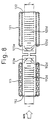
- cutting length L of the protrusion portion louver 112d, 122d is determined to be increased with increasing proximity to the protrusion end of the protrusion portion 112e, 122e as shown in Fig.8.
- the airflow resistance of the protrusion portion louver 112d, 122d may be reduced, and the radiation ability may be improved accordingly.
- the cutting length L at the basal portion side (tube 111, 121 side) of the protrusion portions 112e, 122e having high cooling efficiency is decreased to increase the thermal conductive area, and thereby sufficient amount of heat may be conducted to the basal portion side of the protrusion portions 112e, 122e having high cooling efficiency. For this reason, the improvement in radiation ability appropriate to the increase in radiation area may be surely achieved.
- the flat portion 112h, 122h is provided on which protrusion portion louvers 112d, 122d are not formed.
- the airflow resistance of the region corresponding to the main flow having large flow rate may be reduced, and thereby airflow resistance may be reduced effectively, and the improvement in radiation ability appropriate to the increase in radiation area may be achieved accordingly.
- the flat portions 112h, 122h are provided so that the cutting length L of the protrusion portion louvers 112d, 122d is increased with increasing proximity to the protrusion end of the protrusion portions 112e, 122e as shown in Fig.9, but the flat portion 112h, 122h may be provided so that the cutting length L of the protrusion portion louvers 112d, 122d is decreased with increasing proximity to the protrusion end of the protrusion portions 112e, 122e.
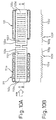
- the cutting angle ⁇ of the protrusion portion louvers 112d, 122d is determined to be decreased with increasing proximity to the protrusion end of the protrusion portions 112e, 122e as shown in Fig.10B.
- the airflow resistance of the protrusion portion louvers 112d, 122d may be reduced, and thereby the improvement in radiation ability appropriate to the increase in radiation area may be achieved.
- the heat exchanger of the aforementioned embodiment is a duplex heat exchanger in which a condenser and a radiator are integrated but the present invention may also provide a single heat exchanger such as a condenser or a radiator.
- Fig.11A ⁇ 11D show a radiator to which the spirit of the first embodiment of the present invention is implemented. It is apparent from Fig.11C that protrusion portion 122e of the fin 122 may be provided at both side ends of the fin 122.
Landscapes
- Engineering & Computer Science (AREA)
- Physics & Mathematics (AREA)
- Thermal Sciences (AREA)
- Mechanical Engineering (AREA)
- General Engineering & Computer Science (AREA)
- Geometry (AREA)
- Heat-Exchange Devices With Radiators And Conduit Assemblies (AREA)
- Air-Conditioning For Vehicles (AREA)
- Cooling Or The Like Of Electrical Apparatus (AREA)
Abstract
Description
Claims (11)
- A heat exchanger comprising a plurality of tubes (111, 121) in which fluid flows and which extend in the direction perpendicular to the direction of airflow, and fins (112, 122) which are provided on the outer surface of the tubes (111, 121) to accelerate the heat exchange between air and the fluid, wherein the fins (112, 122) have protrusion portions (112e, 122e) protruded from an end of the tubes (111, 121) in the width direction of the tube to the direction perpendicular to the longitudinal direction of the tubes (111, 121), and uneven portions (112f, 122f) are formed on the protrusion portions (112e, 122e) without cutting part of the protrusion portions (112e, 122e) to increase the surface area of the fins (112, 122).
- The heat exchanger of claim 1, wherein louvers (112d, 122d) are formed in louver board style by cutting and setting up part of the fins (112, 122) on the other portions than the protrusion portions (112e, 122e) of the fins (112, 122).
- The heat exchanger of claim 2, wherein the uneven portions (112f, 122f) are formed in wave form, and a ridge direction (Dw) ranging over the summits of the crest portions (112g, 122g) of the uneven portions (112f, 122f) is substantially parallel with a cutting direction (Dr) of the louvers 112d, 122d.
- A heat exchanger comprising a plurality of tubes (111, 121) in which fluid flows and which extend in the direction perpendicular to the direction of airflow, and fins (112, 122) which are provided on the outer surface of the tubes (111, 121) to accelerate the heat exchange between air and the fluid, and on which louvers are formed in louver board style by cutting and setting up part of the fins (112, 122), wherein the fins (112, 122) have protrusion portions (112e, 122e) protruded from an end of the tubes (111, 122) in the width direction of the tube to a direction perpendicular to the longitudinal direction of the tubes (111, 121), and the louvers (112d, 122d) formed on the protrusion portions (112e, 122e) are different from the louvers (112d, 122d) formed on the other portions than the protrusion portions (112e, 122e) of the fins (112, 122).
- The heat exchanger of claim 4, wherein the cutting length L of the louvers (112d, 122d) formed on the protrusion portions (112e, 122e) is determined to be decreased with increasing proximity to the protrusion end of the protrusion portions (112e, 122e).
- The heat exchanger of claim 4, wherein the cutting length L of the louvers (112d, 122d) formed on the protrusion portions (112e, 122e) is determined to be increased with increasing proximity to the protrusion end of the protrusion portions (112e, 122e).
- The heat exchanger of claim 4, wherein flat portions (112h, 122h), on which the louvers (112d, 122d) are not formed, are provided in the region on the protrusion portions (112e, 122e) corresponding to the main flow path of air flowing between tubes (111, 121).
- The heat exchanger of claim 4, wherein the cutting angle β, of the louvers (112d, 122d) formed on the protrusion portions (112e, 122e), is determined to be decreased with increasing proximity to the protrusion end of the protrusion portions (112e, 122e).
- A duplex heat exchanger comprising a first heat exchanger (110) which is a heat exchanger of any one of claims 1 to 8, and a second heat exchanger (120) which is a heat exchanger of any one of claims 1 to 8, arranged in series with the first heat exchanger (110) in the direction of airflow, wherein the protrusion portions (112e) of the first heat exchanger (110) are protruded toward the second heat exchanger (120), and the protrusion portions (122e) of the second heat exchanger (120) are protruded toward the first heat exchanger (110).
- The duplex heat exchanger of claim 9, wherein the fin (112) of the first heat exchanger (110) and the fin (122) of the second heat exchanger (120) are integrated.
- The duplex heat exchanger of claim 10, wherein a heat transfer suppressing means (S) for suppressing the heat transfer is provided between the fin (112) of the first heat exchanger (110) and the fin (122) of the second heat exchanger (120).
Applications Claiming Priority (3)
| Application Number | Priority Date | Filing Date | Title |
|---|---|---|---|
| JP35481999 | 1999-12-14 | ||
| JP35481999A JP4482991B2 (en) | 1999-12-14 | 1999-12-14 | Double heat exchanger |
| PCT/JP2000/008827 WO2001044741A1 (en) | 1999-12-14 | 2000-12-13 | Heat exchanger |
Publications (3)
| Publication Number | Publication Date |
|---|---|
| EP1164345A1 true EP1164345A1 (en) | 2001-12-19 |
| EP1164345A4 EP1164345A4 (en) | 2006-04-26 |
| EP1164345B1 EP1164345B1 (en) | 2008-01-23 |
Family
ID=18440121
Family Applications (1)
| Application Number | Title | Priority Date | Filing Date |
|---|---|---|---|
| EP00981693A Expired - Lifetime EP1164345B1 (en) | 1999-12-14 | 2000-12-13 | Heat exchanger |
Country Status (6)
| Country | Link |
|---|---|
| US (1) | US6662861B2 (en) |
| EP (1) | EP1164345B1 (en) |
| JP (1) | JP4482991B2 (en) |
| KR (1) | KR100486923B1 (en) |
| DE (1) | DE60037879T2 (en) |
| WO (1) | WO2001044741A1 (en) |
Cited By (12)
| Publication number | Priority date | Publication date | Assignee | Title |
|---|---|---|---|---|
| EP1229296A1 (en) * | 2001-01-31 | 2002-08-07 | Calsonic Kansei Corporation | Louvered fin for a heat exchanger |
| EP1167909A3 (en) * | 2000-02-08 | 2005-10-12 | Calsonic Kansei Corporation | Core structure of integral heat-exchanger |
| EP1647341A2 (en) | 2004-10-14 | 2006-04-19 | Behr GmbH & Co. KG | Method for making a corrugated fin and heat exchange block containing these corrugated fins |
| EP1712865A1 (en) * | 2005-04-14 | 2006-10-18 | Calsonic Kansei Corporation | Corrugate fin for integrally assembled heat exchangers |
| FR2907887A1 (en) * | 2006-10-25 | 2008-05-02 | Valeo Systemes Thermiques | Heat exchanger for motor vehicle, has fin portions respectively fixed in contact with fluid circulation tubes, where tubes are covered with filler metal plating at level of contact and fin portions are free from plating near rupture |
| EP2336701A3 (en) * | 2009-12-14 | 2017-05-31 | MAHLE International GmbH | Low pressure drop fin with selective micro surface enhancement |
| EP3255368A1 (en) * | 2016-06-09 | 2017-12-13 | Valeo Systemes Thermiques | Heat exchanger, especially a gas radiator or a condenser for a car |
| EP3330657A1 (en) * | 2016-12-01 | 2018-06-06 | Modine Manufacturing Company | Air fin for a heat exchanger, and method of making the same |
| FR3064733A1 (en) * | 2017-04-03 | 2018-10-05 | Valeo Systemes Thermiques | EVAPORATOR FOR AIR CONDITIONING INSTALLATION |
| FR3065519A1 (en) * | 2017-04-21 | 2018-10-26 | Valeo Systemes Thermiques | EVAPORATOR FOR AIR CONDITIONING INSTALLATION |
| EP1632742B1 (en) * | 2004-09-01 | 2018-12-19 | MAHLE Behr GmbH & Co. KG | Heat exchanger, more particularly for air conditioning system |
| EP3483544A4 (en) * | 2016-07-07 | 2019-10-09 | Mitsubishi Electric Corporation | HEAT EXCHANGER |
Families Citing this family (36)
| Publication number | Priority date | Publication date | Assignee | Title |
|---|---|---|---|---|
| US6964296B2 (en) * | 2001-02-07 | 2005-11-15 | Modine Manufacturing Company | Heat exchanger |
| KR100833479B1 (en) * | 2001-12-07 | 2008-05-29 | 한라공조주식회사 | Fin for heat exchanger, heat exchanger having same, and heat exchanger assembly |
| JP4029000B2 (en) * | 2002-01-25 | 2008-01-09 | カルソニックカンセイ株式会社 | Manufacturing method of integrated heat exchanger and integrated heat exchanger |
| DE10218912A1 (en) * | 2002-04-27 | 2003-11-06 | Modine Mfg Co | Corrugated heat exchanger body |
| KR20040014039A (en) * | 2002-08-09 | 2004-02-14 | 한라공조주식회사 | Fin and heat exchanger utilizing the same |
| KR100486565B1 (en) * | 2002-08-20 | 2005-05-03 | 엘지전자 주식회사 | Radiator of heat exchanger |
| KR100492579B1 (en) * | 2002-10-31 | 2005-06-03 | 엘지전자 주식회사 | Drainage apparatus for regenerator |
| FR2849174B1 (en) * | 2002-12-23 | 2006-01-06 | Valeo Thermique Moteur Sa | HEAT EXCHANGE FINISH, ESPECIALLY COOLING, HEAT EXCHANGE MODULE COMPRISING SUCH FIN AND METHOD OF MANUFACTURING HEAT EXCHANGERS USING THE SAME |
| DE10344219A1 (en) * | 2003-09-22 | 2005-04-14 | Behr Gmbh & Co. Kg | Heat exchanger module for a motor vehicle |
| US20050230089A1 (en) * | 2004-04-05 | 2005-10-20 | Denso Corporation | Heat exchanger capable of preventing heat stress |
| JP2006078035A (en) * | 2004-09-08 | 2006-03-23 | Denso Corp | Heat exchanger |
| KR100690891B1 (en) | 2005-05-26 | 2007-03-09 | 엘지전자 주식회사 | Heat exchanger for dryer and condenser dryer using same |
| US20070012430A1 (en) * | 2005-07-18 | 2007-01-18 | Duke Brian E | Heat exchangers with corrugated heat exchange elements of improved strength |
| US7886537B2 (en) * | 2005-09-15 | 2011-02-15 | Cotherm Of America Corporation | Power generation system and associated methods |
| JP2007163083A (en) * | 2005-12-16 | 2007-06-28 | Denso Corp | Corrugated fin and heat exchanger using the same |
| CN101379360A (en) * | 2006-02-01 | 2009-03-04 | 康奈可关精株式会社 | Heat exchanger for vehicle |
| US20070240865A1 (en) * | 2006-04-13 | 2007-10-18 | Zhang Chao A | High performance louvered fin for heat exchanger |
| US20070284086A1 (en) * | 2006-05-04 | 2007-12-13 | Jerome Matter | Transition assembly and method of connecting to a heat exchanger |
| US20090260789A1 (en) * | 2008-04-21 | 2009-10-22 | Dana Canada Corporation | Heat exchanger with expanded metal turbulizer |
| US8196646B2 (en) * | 2008-12-15 | 2012-06-12 | Delphi Technologies, Inc. | Heat exchanger assembly |
| JP5523495B2 (en) * | 2011-04-22 | 2014-06-18 | 三菱電機株式会社 | Finned tube heat exchanger and refrigeration cycle apparatus |
| JP5920179B2 (en) * | 2011-12-05 | 2016-05-18 | 株式会社デンソー | Heat exchanger and heat pump cycle including the same |
| JP2014001869A (en) * | 2012-06-15 | 2014-01-09 | Mitsubishi Electric Corp | Heat exchanger and refrigeration cycle device |
| JP6050995B2 (en) * | 2012-09-18 | 2016-12-21 | 株式会社ケーヒン・サーマル・テクノロジー | Evaporator |
| KR101672092B1 (en) | 2014-07-25 | 2016-11-03 | 두산중공업 주식회사 | Heat exchange tube module |
| CN105890399A (en) * | 2014-10-31 | 2016-08-24 | 丹佛斯微通道换热器(嘉兴)有限公司 | Heat exchanger |
| EP3330637B1 (en) * | 2015-07-29 | 2021-08-25 | Mitsubishi Electric Corporation | Heat exchanger and refrigeration cycle apparatus |
| DE102015119408A1 (en) * | 2015-11-11 | 2017-05-11 | Hanon Systems | Heat exchanger with several cooling circuits |
| DE102016210159A1 (en) * | 2016-06-08 | 2017-12-14 | Mahle International Gmbh | Ribbed element for a heat exchanger |
| JP2018132247A (en) * | 2017-02-15 | 2018-08-23 | 富士電機株式会社 | vending machine |
| CN106985637B (en) * | 2017-03-22 | 2019-07-26 | 广西易德科技有限责任公司 | A kind of automobile air-conditioning refrigeration equipment |
| WO2018230430A1 (en) * | 2017-06-12 | 2018-12-20 | 株式会社デンソー | Heat exchanger and corrugated fin |
| KR102676298B1 (en) * | 2019-05-28 | 2024-06-19 | 한온시스템 주식회사 | Tube-fin type heat exchanger |
| USD967361S1 (en) * | 2020-08-17 | 2022-10-18 | Mercracing, Llc | Heat exchanger |
| CN112228977B (en) * | 2020-11-18 | 2024-04-30 | 珠海格力电器股份有限公司 | Heat pump system and control method, device, air conditioning equipment, and storage medium thereof |
| JP7133063B1 (en) * | 2021-04-14 | 2022-09-07 | マレリ株式会社 | Heat exchanger |
Family Cites Families (23)
| Publication number | Priority date | Publication date | Assignee | Title |
|---|---|---|---|---|
| US1557467A (en) * | 1920-05-10 | 1925-10-13 | Arthur B Modine | Radiator |
| US3298432A (en) * | 1964-05-22 | 1967-01-17 | Przyborowski Stanislaus | Radiators |
| US3437134A (en) * | 1965-10-24 | 1969-04-08 | Borg Warner | Heat exchanger |
| JPS5573184U (en) * | 1978-11-08 | 1980-05-20 | ||
| US4328861A (en) * | 1979-06-21 | 1982-05-11 | Borg-Warner Corporation | Louvred fins for heat exchangers |
| JPS5852471U (en) * | 1981-09-29 | 1983-04-09 | カルソニックカンセイ株式会社 | Corrugated fin type heat exchanger |
| JPS6159195A (en) * | 1984-08-30 | 1986-03-26 | Toyo Radiator Kk | Heat exchanger core |
| JPS6218583U (en) * | 1985-07-18 | 1987-02-04 | ||
| JPS6314092A (en) * | 1986-07-03 | 1988-01-21 | Nippon Denso Co Ltd | Heat exchanger |
| JPH0214582U (en) | 1988-07-08 | 1990-01-30 | ||
| DE3938842A1 (en) * | 1989-06-06 | 1991-05-29 | Thermal Waerme Kaelte Klima | CONDENSER FOR A VEHICLE AIR CONDITIONING REFRIGERANT |
| US4984626A (en) * | 1989-11-24 | 1991-01-15 | Carrier Corporation | Embossed vortex generator enhanced plate fin |
| DE4201791A1 (en) * | 1991-06-20 | 1993-07-29 | Thermal Waerme Kaelte Klima | FLAT TUBES FOR INSTALLATION IN A FLAT TUBE HEAT EXCHANGER AND METHOD FOR SEPARATING THE FLAT TUBES |
| JPH06147785A (en) * | 1992-11-04 | 1994-05-27 | Hitachi Ltd | Outdoor heat exchanger for heat pump |
| US5360060A (en) * | 1992-12-08 | 1994-11-01 | Hitachi, Ltd. | Fin-tube type heat exchanger |
| DE69507070T2 (en) * | 1994-04-12 | 1999-06-10 | Showa Aluminum Corp., Sakai, Osaka | Double heat exchanger in stacked construction |
| US5992514A (en) * | 1995-11-13 | 1999-11-30 | Denso Corporation | Heat exchanger having several exchanging portions |
| JP3630201B2 (en) * | 1996-06-19 | 2005-03-16 | カルソニックカンセイ株式会社 | Integrated heat exchanger |
| WO1998025092A1 (en) * | 1996-12-04 | 1998-06-11 | Zexel Corporation | Heat exchanger |
| US5752567A (en) * | 1996-12-04 | 1998-05-19 | York International Corporation | Heat exchanger fin structure |
| JPH10281693A (en) * | 1997-03-31 | 1998-10-23 | Zexel Corp | Duplx type integral heat-exchanger |
| JP4019113B2 (en) * | 1997-11-13 | 2007-12-12 | 株式会社ティラド | Integrated heat exchanger fin and method of manufacturing the same |
| JP4117429B2 (en) * | 1999-02-01 | 2008-07-16 | 株式会社デンソー | Heat exchanger fins |
-
1999
- 1999-12-14 JP JP35481999A patent/JP4482991B2/en not_active Expired - Fee Related
-
2000
- 2000-12-13 KR KR10-2001-7010117A patent/KR100486923B1/en not_active Expired - Fee Related
- 2000-12-13 WO PCT/JP2000/008827 patent/WO2001044741A1/en not_active Ceased
- 2000-12-13 EP EP00981693A patent/EP1164345B1/en not_active Expired - Lifetime
- 2000-12-13 DE DE60037879T patent/DE60037879T2/en not_active Expired - Lifetime
-
2001
- 2001-08-14 US US09/929,635 patent/US6662861B2/en not_active Expired - Lifetime
Cited By (18)
| Publication number | Priority date | Publication date | Assignee | Title |
|---|---|---|---|---|
| EP1167909A3 (en) * | 2000-02-08 | 2005-10-12 | Calsonic Kansei Corporation | Core structure of integral heat-exchanger |
| US7246438B2 (en) | 2001-01-31 | 2007-07-24 | Calsonic Kansei Corporation | Method for producing a heat exchanger with a louvered fin |
| EP1229296A1 (en) * | 2001-01-31 | 2002-08-07 | Calsonic Kansei Corporation | Louvered fin for a heat exchanger |
| EP1632742B1 (en) * | 2004-09-01 | 2018-12-19 | MAHLE Behr GmbH & Co. KG | Heat exchanger, more particularly for air conditioning system |
| EP1647341A2 (en) | 2004-10-14 | 2006-04-19 | Behr GmbH & Co. KG | Method for making a corrugated fin and heat exchange block containing these corrugated fins |
| EP1712865A1 (en) * | 2005-04-14 | 2006-10-18 | Calsonic Kansei Corporation | Corrugate fin for integrally assembled heat exchangers |
| US7478669B2 (en) | 2005-04-14 | 2009-01-20 | Calsonic Kansei Corporation | Corrugated fin for integrally assembled heat exchangers |
| FR2907887A1 (en) * | 2006-10-25 | 2008-05-02 | Valeo Systemes Thermiques | Heat exchanger for motor vehicle, has fin portions respectively fixed in contact with fluid circulation tubes, where tubes are covered with filler metal plating at level of contact and fin portions are free from plating near rupture |
| EP2336701A3 (en) * | 2009-12-14 | 2017-05-31 | MAHLE International GmbH | Low pressure drop fin with selective micro surface enhancement |
| EP3255368A1 (en) * | 2016-06-09 | 2017-12-13 | Valeo Systemes Thermiques | Heat exchanger, especially a gas radiator or a condenser for a car |
| EP3483544A4 (en) * | 2016-07-07 | 2019-10-09 | Mitsubishi Electric Corporation | HEAT EXCHANGER |
| CN108131980A (en) * | 2016-12-01 | 2018-06-08 | 摩丁制造公司 | Fin for heat exchanger and method of manufacturing the same |
| EP3330657A1 (en) * | 2016-12-01 | 2018-06-06 | Modine Manufacturing Company | Air fin for a heat exchanger, and method of making the same |
| US10436156B2 (en) | 2016-12-01 | 2019-10-08 | Modine Manufacturing Company | Air fin for a heat exchanger, and method of making the same |
| CN108131980B (en) * | 2016-12-01 | 2020-09-08 | 摩丁制造公司 | Fin for heat exchanger and method of making the same |
| US11162742B2 (en) * | 2016-12-01 | 2021-11-02 | Modine Manufacturing Company | Air fin for a heat exchanger |
| FR3064733A1 (en) * | 2017-04-03 | 2018-10-05 | Valeo Systemes Thermiques | EVAPORATOR FOR AIR CONDITIONING INSTALLATION |
| FR3065519A1 (en) * | 2017-04-21 | 2018-10-26 | Valeo Systemes Thermiques | EVAPORATOR FOR AIR CONDITIONING INSTALLATION |
Also Published As
| Publication number | Publication date |
|---|---|
| US20020017381A1 (en) | 2002-02-14 |
| KR20010105346A (en) | 2001-11-28 |
| KR100486923B1 (en) | 2005-05-03 |
| EP1164345A4 (en) | 2006-04-26 |
| US6662861B2 (en) | 2003-12-16 |
| JP4482991B2 (en) | 2010-06-16 |
| DE60037879T2 (en) | 2009-02-19 |
| JP2001174179A (en) | 2001-06-29 |
| EP1164345B1 (en) | 2008-01-23 |
| WO2001044741A1 (en) | 2001-06-21 |
| DE60037879D1 (en) | 2008-03-13 |
Similar Documents
| Publication | Publication Date | Title |
|---|---|---|
| EP1164345A1 (en) | Heat exchanger | |
| US6213196B1 (en) | Double heat exchanger for vehicle air conditioner | |
| JP4117429B2 (en) | Heat exchanger fins | |
| JP4674602B2 (en) | Heat exchanger | |
| JP4379967B2 (en) | Double heat exchanger | |
| US6918432B2 (en) | Heat exchanger | |
| US20090314475A1 (en) | Heat exchanger | |
| EP2778592B1 (en) | Heat exchanger assembly having split mini-louvered fins | |
| US6889757B2 (en) | Core structure of integral heat-exchanger | |
| US20090173477A1 (en) | Heat exchanger fin | |
| US20090301696A1 (en) | Heat exchanger for vehicle | |
| KR100821180B1 (en) | Heat sink fin for heat exchanger | |
| EP1519133A2 (en) | Heat exchanging apparatus | |
| US20070051502A1 (en) | Heat exchanger fin, heat exchanger, condensers, and evaporators | |
| JP2006078035A (en) | Heat exchanger | |
| US20090173479A1 (en) | Louvered air center for compact heat exchanger | |
| US5975200A (en) | Plate-fin type heat exchanger | |
| US20130075071A1 (en) | Heat Exchanger | |
| US20210389057A1 (en) | Heat exchanger | |
| EP0803695B1 (en) | Plate-fin heat exchanger | |
| EP3575728B1 (en) | A core of a heat exchanger comprising corrugated fins | |
| JP5772608B2 (en) | Heat exchanger | |
| KR100812500B1 (en) | Integral fins of compound heat exchanger | |
| US10655530B2 (en) | Intercooler | |
| JP2001255096A (en) | Heat exchanger |
Legal Events
| Date | Code | Title | Description |
|---|---|---|---|
| PUAI | Public reference made under article 153(3) epc to a published international application that has entered the european phase |
Free format text: ORIGINAL CODE: 0009012 |
|
| 17P | Request for examination filed |
Effective date: 20010810 |
|
| AK | Designated contracting states |
Kind code of ref document: A1 Designated state(s): AT BE CH CY DE DK ES FI FR GB GR IE IT LI LU MC NL PT SE TR |
|
| RBV | Designated contracting states (corrected) |
Designated state(s): DE FR |
|
| A4 | Supplementary search report drawn up and despatched |
Effective date: 20060310 |
|
| 17Q | First examination report despatched |
Effective date: 20060907 |
|
| GRAP | Despatch of communication of intention to grant a patent |
Free format text: ORIGINAL CODE: EPIDOSNIGR1 |
|
| GRAS | Grant fee paid |
Free format text: ORIGINAL CODE: EPIDOSNIGR3 |
|
| GRAA | (expected) grant |
Free format text: ORIGINAL CODE: 0009210 |
|
| AK | Designated contracting states |
Kind code of ref document: B1 Designated state(s): DE FR |
|
| REF | Corresponds to: |
Ref document number: 60037879 Country of ref document: DE Date of ref document: 20080313 Kind code of ref document: P |
|
| ET | Fr: translation filed | ||
| PLBE | No opposition filed within time limit |
Free format text: ORIGINAL CODE: 0009261 |
|
| STAA | Information on the status of an ep patent application or granted ep patent |
Free format text: STATUS: NO OPPOSITION FILED WITHIN TIME LIMIT |
|
| 26N | No opposition filed |
Effective date: 20081024 |
|
| REG | Reference to a national code |
Ref country code: FR Ref legal event code: PLFP Year of fee payment: 16 |
|
| REG | Reference to a national code |
Ref country code: FR Ref legal event code: PLFP Year of fee payment: 17 |
|
| REG | Reference to a national code |
Ref country code: FR Ref legal event code: PLFP Year of fee payment: 18 |
|
| PGFP | Annual fee paid to national office [announced via postgrant information from national office to epo] |
Ref country code: DE Payment date: 20171211 Year of fee payment: 18 Ref country code: FR Payment date: 20171221 Year of fee payment: 18 |
|
| REG | Reference to a national code |
Ref country code: DE Ref legal event code: R119 Ref document number: 60037879 Country of ref document: DE |
|
| PG25 | Lapsed in a contracting state [announced via postgrant information from national office to epo] |
Ref country code: DE Free format text: LAPSE BECAUSE OF NON-PAYMENT OF DUE FEES Effective date: 20190702 Ref country code: FR Free format text: LAPSE BECAUSE OF NON-PAYMENT OF DUE FEES Effective date: 20181231 |