EP1164034B1 - Boítier de capteur de pression de pneumatique de véhicule automobile - Google Patents
Boítier de capteur de pression de pneumatique de véhicule automobile Download PDFInfo
- Publication number
- EP1164034B1 EP1164034B1 EP01401554A EP01401554A EP1164034B1 EP 1164034 B1 EP1164034 B1 EP 1164034B1 EP 01401554 A EP01401554 A EP 01401554A EP 01401554 A EP01401554 A EP 01401554A EP 1164034 B1 EP1164034 B1 EP 1164034B1
- Authority
- EP
- European Patent Office
- Prior art keywords
- pressure sensor
- rim
- sensor housing
- housing
- housing according
- Prior art date
- Legal status (The legal status is an assumption and is not a legal conclusion. Google has not performed a legal analysis and makes no representation as to the accuracy of the status listed.)
- Expired - Lifetime
Links
- 210000002105 tongue Anatomy 0.000 abstract description 4
- DOSMHBDKKKMIEF-UHFFFAOYSA-N 2-[3-(diethylamino)-6-diethylazaniumylidenexanthen-9-yl]-5-[3-[3-[4-(1-methylindol-3-yl)-2,5-dioxopyrrol-3-yl]indol-1-yl]propylsulfamoyl]benzenesulfonate Chemical compound C1=CC(=[N+](CC)CC)C=C2OC3=CC(N(CC)CC)=CC=C3C(C=3C(=CC(=CC=3)S(=O)(=O)NCCCN3C4=CC=CC=C4C(C=4C(NC(=O)C=4C=4C5=CC=CC=C5N(C)C=4)=O)=C3)S([O-])(=O)=O)=C21 DOSMHBDKKKMIEF-UHFFFAOYSA-N 0.000 description 17
- 230000005856 abnormality Effects 0.000 description 1
- 230000001133 acceleration Effects 0.000 description 1
- 238000001514 detection method Methods 0.000 description 1
- XOFYZVNMUHMLCC-ZPOLXVRWSA-N prednisone Chemical compound O=C1C=C[C@]2(C)[C@H]3C(=O)C[C@](C)([C@@](CC4)(O)C(=O)CO)[C@@H]4[C@@H]3CCC2=C1 XOFYZVNMUHMLCC-ZPOLXVRWSA-N 0.000 description 1
- 230000000717 retained effect Effects 0.000 description 1
Images
Classifications
-
- B—PERFORMING OPERATIONS; TRANSPORTING
- B60—VEHICLES IN GENERAL
- B60C—VEHICLE TYRES; TYRE INFLATION; TYRE CHANGING; CONNECTING VALVES TO INFLATABLE ELASTIC BODIES IN GENERAL; DEVICES OR ARRANGEMENTS RELATED TO TYRES
- B60C23/00—Devices for measuring, signalling, controlling, or distributing tyre pressure or temperature, specially adapted for mounting on vehicles; Arrangement of tyre inflating devices on vehicles, e.g. of pumps or of tanks; Tyre cooling arrangements
- B60C23/02—Signalling devices actuated by tyre pressure
- B60C23/04—Signalling devices actuated by tyre pressure mounted on the wheel or tyre
- B60C23/0408—Signalling devices actuated by tyre pressure mounted on the wheel or tyre transmitting the signals by non-mechanical means from the wheel or tyre to a vehicle body mounted receiver
-
- Y—GENERAL TAGGING OF NEW TECHNOLOGICAL DEVELOPMENTS; GENERAL TAGGING OF CROSS-SECTIONAL TECHNOLOGIES SPANNING OVER SEVERAL SECTIONS OF THE IPC; TECHNICAL SUBJECTS COVERED BY FORMER USPC CROSS-REFERENCE ART COLLECTIONS [XRACs] AND DIGESTS
- Y10—TECHNICAL SUBJECTS COVERED BY FORMER USPC
- Y10T—TECHNICAL SUBJECTS COVERED BY FORMER US CLASSIFICATION
- Y10T137/00—Fluid handling
- Y10T137/3584—Inflatable article [e.g., tire filling chuck and/or stem]
- Y10T137/3662—With gauge or indicator
Definitions
- Automotive tire wheel pressure sensor used to signal to the driver, through the on-board computer, any abnormality of the tire, which may compromise its safety.
- the sensor is placed in the tire and, precisely, is attached to the circumferential periphery of the rim and plated on it to avoid the vibrations. Since the rims are not universal and there are several diameters of rims, so it is necessary so many types of housing of sensor than rim types. A type of housing is described in JP 04 146 806.
- the housings can therefore be manufactured only by limited series.
- the present invention aims to provide pressure sensor housings universal.
- the invention relates to a pressure sensor housing of automotive vehicle wheel tire arranged to be mounted on the rim of the wheel, characterized by the fact that it comprises support wings of variable height and a receiving well of a fixing dowel integral with the rim.
- height means the distance between the plane of the bearing lines of the wings and the opposite external plane of the housing, a priori fixed in position by relative to the axis of the rims.
- this height corresponds to the radial template of the sensor of the invention.
- the housing can therefore be supported on rims of any radius of curvature.
- the housing can be fixed without any need to adjust to rims of different diameters, while remaining well plated.
- the support wings are elastically deformable.
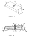
- the housing of the first form of embodiment comprises a body 7 of substantially parallelepiped shape rectangle extending in the circumferential direction of a rim 1 of motor vehicle wheel that carries the housing.
- the casing body 7 is extended at both ends in its direction extension, by two respective wings 3 and 4, of support on the rim 1, and precisely on the surface portion thereof substantially shaped cylindrical on which will be mounted the tire.
- the wings 3, 4, here elastically deformable, are of variable height and are supported by the rim 1 by two curved end portions 31, 32.
- the wings 3, 4 are therefore supported on two zones of the rim 1 angularly distant and the casing body 7 extends in the angular sector considered, with a radial gap between the surface of the rim 1, which is a circle in FIG. and the surface 72, here called lower, of the casing body 7, that is to say that turned inwards, towards the rim 1.
- the wings 3, 4 each extend substantially in a plane parallel to the axis of the rim 1, and precisely they are, at rest, substantially parallel to the end faces of the body 7 to which they attach respectively.
- the wings 3, 4 are attached here to the body 7 substantially to the height of the surface 71, said upper body 7 turned towards the outside, opposite the rim 1.
- a pin 21 is fixed to the cylindrical surface of the rim 1 and protrudes radially outwardly to receive the housing 3, 4, 7 which comprises for this purpose a well 6 for receiving the fixing pin 21, the well 6 being here central and therefore located midway between the two lateral wings 3, 4.
- the radial direction designates, unless indicated contrary, a direction orthogonal to the axis of rotation of the rim 1 and more precisely, it designates the radial direction directed along the axis 20 of the stud 21 and well 6.
- here is meant by horizontal plane all plane perpendicular to this radial detection, considered here as being a vertical. It is conceivable that this is a special case facilitate the description and in no way any limitation of the invention.
- a printed circuit board 9 parallel to the horizontal surfaces 71, 72, carrying active sensor components, and a battery 40 feeding card 9, arranged on the other side.
- the stud 21 has, in the zone of its free end, a throat circular 22, extending in a so-called horizontal plane, intended to cooperate with a vertical crown of elastic tongues or ratchets of clipping 8, secured to the body 7 and extending radially outwardly from the area of the upper surface 71 surrounding the hole of the well 6.
- the radial distance from the rim 1 to the groove 22 is sufficient to guarantee the existence of the radial gap, mentioned above, between the lower surface 72 of the body 7 and the rim 1.
- the wings 3, 4 compensate, by their elasticity, the variations of the height of the body of casing 7 according to the value of the diameter of the rim 1 these variations of height being considered in the vertical direction of stud 21, the length determines the mounting height of the casing body 7 on the rim 1.
- the housing 3, 4, 7 is thus fixed with locking in position, the ratchets 8 preventing any upward withdrawal of the body 7 relative to the stud 21, under the action of acceleration and / or elastic wings 3, 4 which tend to push it away from the rim 1.
- the wings 3, 4 cling, through the body 7 and the pawls 8, on the free end of the stud 21, to exert a elastic return force of their bearing ends 31, 32 towards the rim 1.
- the pawls 8 allow a quick assembly by clipping the housing 3, 4, 7 on the rim 1 since they lock it in position as soon as the groove 22 sufficiently emerges from well 6. As shown, the clicks 8 provide an unmountable fixation.
- the groove 22 presents a upper slope of conical shape, and no longer in a horizontal plane, which allows to separate the pawls 8 by exerting on the housing 7 a force pulling up intensity exceeding the resistance threshold of the ratchets 8.
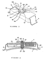
- Figures 3 and 4 illustrate the second embodiment. The elements similar to those in Figures 1 and 2 have retained their reference. Figures 3 and 4 are intended primarily to illustrate another fastening mechanism of the casing body 7 on the bolt 21 comprising the groove 22.
- the clip 10 is in the form of a plate comprising, at a end, two protuberances 12, 13 constituting a fork sone intended to partially surround the stud 21 by engaging in the 22 to thereby block any vertical movement between the stud 21 and the clips 10, in order to block any subsequent sliding of the housing 7 on the stud 21.
- the clip 10 slides on the upper surface 71 and cooperates with two opposing lateral guides 18, 19 which make it possible to slide front in the direction of the horizontal arrow 30, to reach its functional position above cooperation with the throat 22, and in back to clear it.
- the direction of the arrow 30 is the direction of extension of the housing 7.
- the direction of the arrow 30 maneuvering the clip 10 is substantially orthogonal the support wings 3, 4 which are substantially parallel to the faces corresponding ends of the body 7, extending in planes substantially vertical and one of which is visible on the right side of the figure 3.
- the surface 71 on which slides the clips 10 and the guides 18, 19 therefore form a kind of fitted sleeve allowing no that the sliding clip 10 in one direction or the other according to the direction of the arrow 30.
- this one has two lateral resilient tongues 14, 15, deformable in the plane of the clips 10, each having an external lateral zone 16, 17 forming a wedge, extending in a vertical plane inclined relative to the direction of the arrow 30 and partially turned in this direction.
- two lateral stops 31, 32 in the form of vertical rods secured to the surface 71, have a spacing slightly less than the size of the portion of the tabs 14, 15 comprising the inclined zones 16, 17.
- the unlocking of the clip 10 is done manually, by pressing laterally on the two tabs 14, 15, to bring them together in order to engage between the stops 31, 32 by sliding back the clip 10.
- the stops 31, 32 nonreturn also have, in this example, a function of coarse lateral guidance of the base 11 of the clip 10 opposite to the protuberances 12, 13 and they therefore cooperate with the guides 18, 19.
Landscapes
- Engineering & Computer Science (AREA)
- Mechanical Engineering (AREA)
- Measuring Fluid Pressure (AREA)
- Snaps, Bayonet Connections, Set Pins, And Snap Rings (AREA)
- Clamps And Clips (AREA)
- Arrangements For Transmission Of Measured Signals (AREA)
Description
- la figure 1 est une vue en perspective de la première forme de réalisation du boítier de l'invention,
- la figure 2 est une vue en coupe du boítier de la figure 1 dans un plan radial d'une jante sur laquelle il est monté,
- la figure 3 est une vue en perspective de la deuxième forme de réalisation du boítier de l'invention et
- la figure 4 est une vue en coupe du boítier de la figure 3 dans un plan radial d'une jante sur laquelle il est monté.
Claims (8)
- Boítier de capteur de pression de pneumatique de véhicule automobile agencé pour être monté sur une jante (1), caractérisé par le fait qu'il comporte des ailes d'appui (3, 4) de hauteur variable et un puits (6) de réception d'un goujon de fixation (21) solidaire de la jante (1).
- Boítier selon la revendication 1, dans lequel les ailes d'appui (3, 4) sont élastiquement déformables.
- Boítier de capteur de pression selon l'une des revendications 1 et 2, dans lequel il est prévu des moyens (8; 10, 18, 19, 31, 32) de fixation et de verrouillage en position.
- Boítier de capteur de pression selon la revendication 3, dans lequel les moyens de fixation et de verrouillage sont des moyens de clipsage (8; 10).
- Boítier de capteur de pression selon la revendication 3, dans lequel les moyens de verrouillage (8) sont déverrouillables.
- Boítier de capteur de pression selon la revendication 5, dans lequel les moyens de verrouillage comprennent un clips amovible (10).
- Boítier de capteur de pression selon la revendication 6, dans lequel le clips amovible (10) est monté mobile sensiblement orthogonalement aux ailes d'appui (3, 4).
- Boítier de capteur de pression selon l'une des revendications 1 à 7, dans lequel le puits de réception (6) est central et situé à mi-distance des ailes d'appui (3, 4).
Applications Claiming Priority (2)
| Application Number | Priority Date | Filing Date | Title |
|---|---|---|---|
| FR0007625A FR2810272B1 (fr) | 2000-06-15 | 2000-06-15 | Boitier de capteur de pression de pneumatique de vehicule automobile |
| FR0007625 | 2000-06-15 |
Publications (2)
| Publication Number | Publication Date |
|---|---|
| EP1164034A1 EP1164034A1 (fr) | 2001-12-19 |
| EP1164034B1 true EP1164034B1 (fr) | 2005-11-23 |
Family
ID=8851282
Family Applications (1)
| Application Number | Title | Priority Date | Filing Date |
|---|---|---|---|
| EP01401554A Expired - Lifetime EP1164034B1 (fr) | 2000-06-15 | 2001-06-14 | Boítier de capteur de pression de pneumatique de véhicule automobile |
Country Status (6)
| Country | Link |
|---|---|
| US (1) | US6672150B2 (fr) |
| EP (1) | EP1164034B1 (fr) |
| JP (1) | JP2002039900A (fr) |
| AT (1) | ATE310647T1 (fr) |
| DE (1) | DE60115146D1 (fr) |
| FR (1) | FR2810272B1 (fr) |
Families Citing this family (32)
| Publication number | Priority date | Publication date | Assignee | Title |
|---|---|---|---|---|
| US8266465B2 (en) | 2000-07-26 | 2012-09-11 | Bridgestone Americas Tire Operation, LLC | System for conserving battery life in a battery operated device |
| US7161476B2 (en) * | 2000-07-26 | 2007-01-09 | Bridgestone Firestone North American Tire, Llc | Electronic tire management system |
| FR2828657B1 (fr) * | 2001-08-16 | 2003-11-21 | Siemens Automotive Sa | Capteur de pression destine a etre monte dans un pneumatique |
| FR2839683B1 (fr) * | 2002-05-15 | 2005-02-18 | Johnson Contr Automotive Elect | Capteur de pression sur valve de pneumatique |
| US6952160B1 (en) * | 2002-08-07 | 2005-10-04 | Ford Global Technologies, Llc | Method and apparatus, for identifying the location of pressure sensors in a tire pressure monitoring system |
| JP4040488B2 (ja) * | 2003-02-12 | 2008-01-30 | 本田技研工業株式会社 | タイヤ空気圧検知装置の取付構造 |
| DE10314498A1 (de) * | 2003-03-27 | 2004-10-14 | Beru Ag | Formteil zur Verbindung mit einer Felge und Felge, die mit einem Formteil verbunden ist |
| US20060220812A1 (en) * | 2003-06-02 | 2006-10-05 | Siemens Vdo Automotive | Wheel unit for motor vehicle tyre pressure monitoring device |
| JP2005067543A (ja) * | 2003-08-27 | 2005-03-17 | Pacific Ind Co Ltd | タイヤ状態監視装置用送信機のケーシング構造 |
| JP4166735B2 (ja) * | 2004-08-04 | 2008-10-15 | 太平洋工業株式会社 | タイヤ状態監視装置における送信機ユニット |
| DE102004037956A1 (de) * | 2004-08-05 | 2006-02-23 | Dr.Ing.H.C. F. Porsche Ag | Radsensor für Reifendruckkontrolleirichtung mit Halterung |
| US6904795B1 (en) * | 2004-09-14 | 2005-06-14 | Lear Corporation | Sealed mounting of tire monitoring assembly |
| US7224269B2 (en) * | 2004-12-15 | 2007-05-29 | Ford Global Technologies, Llc | Method and system for resetting tire pressure monitoring system for an automotive vehicle |
| US7082817B1 (en) * | 2004-12-20 | 2006-08-01 | Mobiletron Electronics Co., Ltd. | Wireless tire pressure monitoring device (WTPMD) shell structure |
| JP4209395B2 (ja) | 2005-01-21 | 2009-01-14 | 太平洋工業株式会社 | タイヤ監視ユニット |
| US7404427B2 (en) * | 2005-02-02 | 2008-07-29 | Hunter Engineering Company | Vehicle tire changer with integrated detector for tire pressure sensors |
| US7441452B2 (en) * | 2005-05-09 | 2008-10-28 | Ford Global Technologies, Llc | TPMS sensor assembly and method therefore |
| US7369043B2 (en) | 2005-05-11 | 2008-05-06 | Ford Global Technologies, Llc | Method and apparatus for automatically identifying the location of pressure sensors in a tire pressure monitoring system |
| US7281421B2 (en) * | 2005-06-03 | 2007-10-16 | Temic Automotive Of North America, Inc. | Package for a tire pressure sensor assembly |
| US7284418B2 (en) * | 2005-06-03 | 2007-10-23 | Temic Automotive Of North America, Inc. | Tire pressure sensor assembly |
| US7570157B2 (en) * | 2005-10-24 | 2009-08-04 | Ford Global Technologies, Llc | Method and apparatus for adjusting the pressure sensor measurement range in a tire pressure monitoring system |
| US7705717B2 (en) * | 2005-11-30 | 2010-04-27 | Ford Global Technologies | Method and apparatus for receiving signals from a sensor into a tire pressure monitoring system |
| US7421902B2 (en) * | 2006-10-13 | 2008-09-09 | Smartire Systems, Inc. | Fluid pressure sensing method and apparatus |
| CN201045599Y (zh) * | 2007-04-20 | 2008-04-09 | 车王电子股份有限公司 | 胎压侦测器 |
| US7937998B2 (en) * | 2009-03-19 | 2011-05-10 | Deere & Company | Sensor mount with self-tightening device |
| JP5417058B2 (ja) * | 2009-06-23 | 2014-02-12 | 株式会社ブリヂストン | 部品固定機構及びタイヤ組立体 |
| US8640534B2 (en) | 2011-08-22 | 2014-02-04 | Bendix Commercial Vehicle Systems Llc | Mounting method and device for tire pressure monitoring sensor |
| DE102014011949A1 (de) * | 2014-08-14 | 2016-02-18 | Huf Hülsbeck & Fürst Gmbh & Co. Kg | Reifendrucküberwachungseinheit mit einem Zweikomponentengehäuse |
| CN106965634B (zh) * | 2017-04-19 | 2019-07-16 | 铁将军汽车电子股份有限公司 | 胎压传感装置及汽车 |
| DE202019104976U1 (de) * | 2019-09-09 | 2020-12-10 | Maxion Wheels Holding Gmbh | Fahrzeugrad mit Überwachungseinrichtung und Überwachungseinrichtung für Fahrzeugräder |
| GB2599613B (en) * | 2020-04-29 | 2022-09-28 | Tpms Tape Ltd | Internal sensor fixing |
| US11698145B2 (en) * | 2021-04-28 | 2023-07-11 | Battelle Energy Alliance, Llc | Devices and systems for measuring the state of a valve, and related methods |
Family Cites Families (7)
| Publication number | Priority date | Publication date | Assignee | Title |
|---|---|---|---|---|
| US4000639A (en) * | 1975-04-08 | 1977-01-04 | Postema Leonard F | Tool and method for trueing wheel rims |
| FR2308518A1 (fr) * | 1975-04-21 | 1976-11-19 | Michelin & Cie | Perfectionnements aux detecteurs de variation de la pression de gonflage de pneumatiques |
| US4036273A (en) * | 1975-06-16 | 1977-07-19 | Kemper Kenneth E | Traction augmenting road grips |
| FR2661373B1 (fr) * | 1990-04-27 | 1994-10-28 | Jaeger | Detecteur de pression de pneumatiques. |
| US5731754A (en) * | 1994-06-03 | 1998-03-24 | Computer Methods Corporation | Transponder and sensor apparatus for sensing and transmitting vehicle tire parameter data |
| US5637926A (en) * | 1996-02-20 | 1997-06-10 | Delco Electronics Corp. | Battery powered electronic assembly for wheel attachment |
| US6082192A (en) * | 1998-11-13 | 2000-07-04 | Bridgestone/Firestone, Inc. | Non-attached monitoring assembly for pneumatic tire |
-
2000
- 2000-06-15 FR FR0007625A patent/FR2810272B1/fr not_active Expired - Fee Related
-
2001
- 2001-06-12 US US09/879,614 patent/US6672150B2/en not_active Expired - Fee Related
- 2001-06-12 JP JP2001176975A patent/JP2002039900A/ja active Pending
- 2001-06-14 DE DE60115146T patent/DE60115146D1/de not_active Expired - Lifetime
- 2001-06-14 AT AT01401554T patent/ATE310647T1/de not_active IP Right Cessation
- 2001-06-14 EP EP01401554A patent/EP1164034B1/fr not_active Expired - Lifetime
Also Published As
| Publication number | Publication date |
|---|---|
| ATE310647T1 (de) | 2005-12-15 |
| FR2810272A1 (fr) | 2001-12-21 |
| DE60115146D1 (de) | 2005-12-29 |
| JP2002039900A (ja) | 2002-02-06 |
| US6672150B2 (en) | 2004-01-06 |
| US20020029627A1 (en) | 2002-03-14 |
| FR2810272B1 (fr) | 2002-08-30 |
| EP1164034A1 (fr) | 2001-12-19 |
Similar Documents
| Publication | Publication Date | Title |
|---|---|---|
| FR2810272A1 (fr) | Boitier de capteur de pression de pneumatique de vehicule automobile | |
| FR2887830A1 (fr) | Fixation d'un mecanisme d'entrainement d'un dispositif d'essuyage sur un element de structure de caisse | |
| EP0444996B1 (fr) | Dispositif de fixation d'une colonne de direction sur la carrosserie d'un véhicule automobile | |
| EP3095684B1 (fr) | Patte de derailleur | |
| EP0455558B1 (fr) | Dispositif d'immobilisation axiale temporaire d'un axe dans un corps tel qu'un tube enveloppé de colonne de direction | |
| EP1870602B1 (fr) | Pièce d'assemblage de deux éléments entre eux, dispositif d'assemblage associé et application au domaine de l'automobile | |
| EP1681223A1 (fr) | Dispositif de blocage en position d'une colonne de direction réglable de véhicule automobile, ensemble comprenant un tel dispositif, et véhicule automobile comprenant un tel ensemble | |
| FR3098166A1 (fr) | Dispositif de montage amovible d’un module de coussin gonflable sur un volant | |
| FR2768203A1 (fr) | Securite d'engagement a basculement d'un dispositif de maintien en position d'un systeme de serrage de deux elements | |
| EP2678212A1 (fr) | Dispositif destine a la fixation d'une roue de secours d'un vehicule | |
| EP3209908A1 (fr) | Dispositif permettant de contrôler la position d'un levier de commande d'une boîte de vitesses | |
| FR2814702A1 (fr) | Boitier pour capteur de pression de pneumatique de vehicule automobile | |
| EP1179469B1 (fr) | Colonne de direction pour un système de direction de véhicule automobile | |
| EP4321384B1 (fr) | Porte-charge d'un véhicule automobile | |
| EP2214950B1 (fr) | Dispositif de fixation d'une roue de secours d'un vehicule automobile | |
| EP0018240A1 (fr) | Fixation pour conteneur suspendu | |
| EP1721795B1 (fr) | Dispositif et procédé de fixation d'un mécanisme d'essuie-vitre sur une partie de caisse de véhicule, et véhicule automobile équipé d'un tel dispositif | |
| FR2998535A1 (fr) | Dispositif de fixation d'une roue dans un logement d'un vehicule et vehicule comportant un tel dispositif de fixation | |
| EP1762279A1 (fr) | Equipement de golf comprenant un sac de golf et un chariot de support de celui-ci | |
| FR2750102A1 (fr) | Boite-cale pour maintenir un vehicule afin d'eviter le deplacement intempestif du vehicule | |
| EP1870287A1 (fr) | Boîtier d'outillage logé dans la roue de secours d'un véhicule automobile | |
| EP3119620B1 (fr) | Système d'accouplement d'une gamme de porte-charge avec un crochet a rotule fixé a la structure arrière d'un véhicule automobile | |
| EP0964167B1 (fr) | Dispositif pour la fixation d'une unité hydraulique, notamment d'un système antiblocage de roues, dans le compartiment moteur d'un véhicule automobile | |
| FR3157482A1 (fr) | dispositif d’attache | |
| FR3161385A1 (fr) | Enjoliveur pour une jante d’une roue d’un véhicule automobile |
Legal Events
| Date | Code | Title | Description |
|---|---|---|---|
| PUAI | Public reference made under article 153(3) epc to a published international application that has entered the european phase |
Free format text: ORIGINAL CODE: 0009012 |
|
| AK | Designated contracting states |
Kind code of ref document: A1 Designated state(s): AT BE CH CY DE DK ES FI FR GB GR IE IT LI LU MC NL PT SE TR |
|
| AX | Request for extension of the european patent |
Free format text: AL;LT;LV;MK;RO;SI |
|
| 17P | Request for examination filed |
Effective date: 20020618 |
|
| AKX | Designation fees paid |
Free format text: AT BE CH CY DE DK ES FI FR GB GR IE IT LI LU MC NL PT SE TR |
|
| RAP1 | Party data changed (applicant data changed or rights of an application transferred) |
Owner name: JOHNSON CONTROLS AUTOMOTIVE ELECTRONICS |
|
| 17Q | First examination report despatched |
Effective date: 20041116 |
|
| GRAP | Despatch of communication of intention to grant a patent |
Free format text: ORIGINAL CODE: EPIDOSNIGR1 |
|
| GRAS | Grant fee paid |
Free format text: ORIGINAL CODE: EPIDOSNIGR3 |
|
| GRAA | (expected) grant |
Free format text: ORIGINAL CODE: 0009210 |
|
| AK | Designated contracting states |
Kind code of ref document: B1 Designated state(s): AT BE CH CY DE DK ES FI FR GB GR IE IT LI LU MC NL PT SE TR |
|
| PG25 | Lapsed in a contracting state [announced via postgrant information from national office to epo] |
Ref country code: IT Free format text: LAPSE BECAUSE OF FAILURE TO SUBMIT A TRANSLATION OF THE DESCRIPTION OR TO PAY THE FEE WITHIN THE PRESCRIBED TIME-LIMIT;WARNING: LAPSES OF ITALIAN PATENTS WITH EFFECTIVE DATE BEFORE 2007 MAY HAVE OCCURRED AT ANY TIME BEFORE 2007. THE CORRECT EFFECTIVE DATE MAY BE DIFFERENT FROM THE ONE RECORDED. Effective date: 20051123 Ref country code: IE Free format text: LAPSE BECAUSE OF FAILURE TO SUBMIT A TRANSLATION OF THE DESCRIPTION OR TO PAY THE FEE WITHIN THE PRESCRIBED TIME-LIMIT Effective date: 20051123 Ref country code: GB Free format text: LAPSE BECAUSE OF FAILURE TO SUBMIT A TRANSLATION OF THE DESCRIPTION OR TO PAY THE FEE WITHIN THE PRESCRIBED TIME-LIMIT Effective date: 20051123 Ref country code: NL Free format text: LAPSE BECAUSE OF FAILURE TO SUBMIT A TRANSLATION OF THE DESCRIPTION OR TO PAY THE FEE WITHIN THE PRESCRIBED TIME-LIMIT Effective date: 20051123 Ref country code: AT Free format text: LAPSE BECAUSE OF FAILURE TO SUBMIT A TRANSLATION OF THE DESCRIPTION OR TO PAY THE FEE WITHIN THE PRESCRIBED TIME-LIMIT Effective date: 20051123 Ref country code: FI Free format text: LAPSE BECAUSE OF FAILURE TO SUBMIT A TRANSLATION OF THE DESCRIPTION OR TO PAY THE FEE WITHIN THE PRESCRIBED TIME-LIMIT Effective date: 20051123 |
|
| REG | Reference to a national code |
Ref country code: GB Ref legal event code: FG4D Free format text: NOT ENGLISH |
|
| REG | Reference to a national code |
Ref country code: CH Ref legal event code: EP |
|
| REF | Corresponds to: |
Ref document number: 60115146 Country of ref document: DE Date of ref document: 20051229 Kind code of ref document: P |
|
| REG | Reference to a national code |
Ref country code: IE Ref legal event code: FG4D Free format text: LANGUAGE OF EP DOCUMENT: FRENCH |
|
| PG25 | Lapsed in a contracting state [announced via postgrant information from national office to epo] |
Ref country code: GR Free format text: LAPSE BECAUSE OF FAILURE TO SUBMIT A TRANSLATION OF THE DESCRIPTION OR TO PAY THE FEE WITHIN THE PRESCRIBED TIME-LIMIT Effective date: 20060223 Ref country code: DK Free format text: LAPSE BECAUSE OF FAILURE TO SUBMIT A TRANSLATION OF THE DESCRIPTION OR TO PAY THE FEE WITHIN THE PRESCRIBED TIME-LIMIT Effective date: 20060223 Ref country code: SE Free format text: LAPSE BECAUSE OF FAILURE TO SUBMIT A TRANSLATION OF THE DESCRIPTION OR TO PAY THE FEE WITHIN THE PRESCRIBED TIME-LIMIT Effective date: 20060223 |
|
| PG25 | Lapsed in a contracting state [announced via postgrant information from national office to epo] |
Ref country code: DE Free format text: LAPSE BECAUSE OF FAILURE TO SUBMIT A TRANSLATION OF THE DESCRIPTION OR TO PAY THE FEE WITHIN THE PRESCRIBED TIME-LIMIT Effective date: 20060224 |
|
| PG25 | Lapsed in a contracting state [announced via postgrant information from national office to epo] |
Ref country code: ES Free format text: LAPSE BECAUSE OF FAILURE TO SUBMIT A TRANSLATION OF THE DESCRIPTION OR TO PAY THE FEE WITHIN THE PRESCRIBED TIME-LIMIT Effective date: 20060306 |
|
| PG25 | Lapsed in a contracting state [announced via postgrant information from national office to epo] |
Ref country code: PT Free format text: LAPSE BECAUSE OF FAILURE TO SUBMIT A TRANSLATION OF THE DESCRIPTION OR TO PAY THE FEE WITHIN THE PRESCRIBED TIME-LIMIT Effective date: 20060424 |
|
| NLV1 | Nl: lapsed or annulled due to failure to fulfill the requirements of art. 29p and 29m of the patents act | ||
| GBV | Gb: ep patent (uk) treated as always having been void in accordance with gb section 77(7)/1977 [no translation filed] |
Effective date: 20051123 |
|
| REG | Reference to a national code |
Ref country code: IE Ref legal event code: FD4D |
|
| PG25 | Lapsed in a contracting state [announced via postgrant information from national office to epo] |
Ref country code: CH Free format text: LAPSE BECAUSE OF NON-PAYMENT OF DUE FEES Effective date: 20060630 Ref country code: MC Free format text: LAPSE BECAUSE OF NON-PAYMENT OF DUE FEES Effective date: 20060630 Ref country code: LI Free format text: LAPSE BECAUSE OF NON-PAYMENT OF DUE FEES Effective date: 20060630 Ref country code: BE Free format text: LAPSE BECAUSE OF NON-PAYMENT OF DUE FEES Effective date: 20060630 |
|
| PLBE | No opposition filed within time limit |
Free format text: ORIGINAL CODE: 0009261 |
|
| STAA | Information on the status of an ep patent application or granted ep patent |
Free format text: STATUS: NO OPPOSITION FILED WITHIN TIME LIMIT |
|
| 26N | No opposition filed |
Effective date: 20060824 |
|
| REG | Reference to a national code |
Ref country code: CH Ref legal event code: PL |
|
| REG | Reference to a national code |
Ref country code: FR Ref legal event code: ST Effective date: 20070228 |
|
| BERE | Be: lapsed |
Owner name: JOHNSON CONTROLS AUTOMOTIVE ELECTRONICS Effective date: 20060630 |
|
| PG25 | Lapsed in a contracting state [announced via postgrant information from national office to epo] |
Ref country code: FR Free format text: LAPSE BECAUSE OF NON-PAYMENT OF DUE FEES Effective date: 20060630 |
|
| PG25 | Lapsed in a contracting state [announced via postgrant information from national office to epo] |
Ref country code: LU Free format text: LAPSE BECAUSE OF NON-PAYMENT OF DUE FEES Effective date: 20060614 Ref country code: TR Free format text: LAPSE BECAUSE OF FAILURE TO SUBMIT A TRANSLATION OF THE DESCRIPTION OR TO PAY THE FEE WITHIN THE PRESCRIBED TIME-LIMIT Effective date: 20051123 |
|
| PG25 | Lapsed in a contracting state [announced via postgrant information from national office to epo] |
Ref country code: CY Free format text: LAPSE BECAUSE OF FAILURE TO SUBMIT A TRANSLATION OF THE DESCRIPTION OR TO PAY THE FEE WITHIN THE PRESCRIBED TIME-LIMIT Effective date: 20051123 |