EP1162488A2 - Optical fiber aerial cable and manufacturing method - Google Patents
Optical fiber aerial cable and manufacturing method Download PDFInfo
- Publication number
- EP1162488A2 EP1162488A2 EP01112747A EP01112747A EP1162488A2 EP 1162488 A2 EP1162488 A2 EP 1162488A2 EP 01112747 A EP01112747 A EP 01112747A EP 01112747 A EP01112747 A EP 01112747A EP 1162488 A2 EP1162488 A2 EP 1162488A2
- Authority
- EP
- European Patent Office
- Prior art keywords
- cable according
- air cable
- cable
- elements
- polymer
- Prior art date
- Legal status (The legal status is an assumption and is not a legal conclusion. Google has not performed a legal analysis and makes no representation as to the accuracy of the status listed.)
- Withdrawn
Links
Images

Classifications
-
- G—PHYSICS
- G02—OPTICS
- G02B—OPTICAL ELEMENTS, SYSTEMS OR APPARATUS
- G02B6/00—Light guides; Structural details of arrangements comprising light guides and other optical elements, e.g. couplings
- G02B6/44—Mechanical structures for providing tensile strength and external protection for fibres, e.g. optical transmission cables
- G02B6/4401—Optical cables
- G02B6/4415—Cables for special applications
- G02B6/4416—Heterogeneous cables
- G02B6/4417—High voltage aspects, e.g. in cladding
- G02B6/4419—Preventing corona discharge
-
- G—PHYSICS
- G02—OPTICS
- G02B—OPTICAL ELEMENTS, SYSTEMS OR APPARATUS
- G02B6/00—Light guides; Structural details of arrangements comprising light guides and other optical elements, e.g. couplings
- G02B6/44—Mechanical structures for providing tensile strength and external protection for fibres, e.g. optical transmission cables
- G02B6/4401—Optical cables
- G02B6/4415—Cables for special applications
- G02B6/4416—Heterogeneous cables
- G02B6/4422—Heterogeneous cables of the overhead type
Definitions
- optical fiber aerial cables in their central and high-voltage roads enable energy supply companies to all conurbations in a region as well as their larger towns and cities bypassing the networks state and / or private telecommunications companies to connect with each other in terms of communications.
- ADL cable A ll- D ielectric- L ash
- self-supporting overhead cables with non-metallic strain relief elements A ll- D ielectric- S eleven S upporting- or ADSS cable
- ADL cable not have their own supporting members. They are usually attached to an already installed earth or phase cable of the high-voltage overhead line using an adhesive or lashing tape.
- An overview relating to optical aerial cables can be found, for example, in G. Mahlke; P. Gössing: "Optical fiber cable”; Publicis MCD publishing house; 5th edition 1998, pp. 157 - 162.
- the invention relates to a versatile Air cable, especially one in the electrical field of a high-voltage overhead line removable, purely dielectric optical Communication cable, the sheath of which has a long service life having.
- the cable should be comparatively simple, can be produced variably and inexpensively.
- an air cable comprising: at least one optical transmission element arranged in a protective sheath, at least one tensile element, an outer sheath and a plurality of strand-like or thread-like elements completely embedded in the sheath material, the strand-like or thread-like elements consisting of one semiconducting polymer or a semiconducting polymer mixture and the electrical resistance of the polymer or polymer mixture is in the range of 10 5 ⁇ / m and 10 9 ⁇ / m.
- the dependent claims have preferred configurations and developments of the aerial cable to the subject.
- the method for producing such a cable is carried out by Provide at least one optical transmission element containing cable core with an outer jacket, several melted strands or threads from a semiconducting properties having polymer or a semiconducting properties having polymer mixture by using the Technique of coextrusion into the molten jacket material be embedded.
- the induced electrical charges by means of semiconducting, in the PE sheath of completely embedded melt threads guy spirals attached to the mast and at ground potential derived. Even on the still wet and only in places Dried coat surface can therefore no larger Potential differences occur in the longitudinal direction of the cable.
- the melt threads can be more easily Way in the desired number, the required thickness and with a specified radial distance to the longitudinal axis of the cable running parallel to the longitudinal axis of the cable in the jacket material embed. The latter contributes significantly to the homogenization of the Field course along the cable at.
- optical fibers optionally stranded together and each consisting of a glass core (refractive index n K ), a glass jacket ("cladding"; refractive index n C ⁇ n K ) and an outer, usually colored lacquer layer ("coating"; refractive index n Coa > n K ) 3 are arranged with excess length ( ⁇ 5 ⁇ ) in the tubular protective sheath of the maxi loose tube 2 and are therefore not subjected to any or only weak tensile forces even in the tensioned ADSS cable 1.
- a chemically neutral, slightly thixotropic substance 4 that does not drip or freeze in the temperature range between -40 ° C. and + 70 ° C. prevents water from penetrating into the loose tube 2 and spreading in the direction of the longitudinal axis of the cable.
- the tensile forces acting on the ADSS cable 1 are determined by the arranged symmetrically with respect to the longitudinal axis of the cable, in Cross section elliptical or circular and for example consisting of bundled aramid yarns or threads (Kevlar) Elements 5/5 'added.
- the cable manufacturer must do so Make sure that the aramid yarns and threads and the extruded Do not bake the jacket material together.
- Aramid yarns can of course also be used other tensile materials, especially glass fibers (rovings) or ultra high molecular weight polyolefin fibers (trade name Use "Dynema").
- the 1.7 mm thick outer jacket 6 of the aerial cable, for example 1 is preferably made of polyethylene (PE), especially that with the help of catalysts in a special low-pressure process manufactured LMDPE (Linear-Medium-Density-PE).
- PE polyethylene
- LMDPE Linear-Medium-Density-PE
- the heavily used, the weather and intense solar radiation exposed PE contains the usual additives such as carbon black, antioxidants, degradation inhibitors, pigments etc. in the amounts required for the respective application (see for example WO 99/04300).
- the outer sheath 6 contains a plurality of melt threads, which are preferably aligned parallel to one another and are arranged symmetrically with respect to the longitudinal axis of the cable 7/7 ', whose electrical resistance is in the range between 10 5 ⁇ / m and 10 9 ⁇ / m.
- the conductivity of the melt threads 7/7 'consisting of a polymer or a polymer mixture (compound) is essentially based on the content of carbon or carbon black, the proportion of which in the polymer matrix is 10% by weight to max. Is 40% by weight.
- the polymer or the polymer mixture can also contain an antioxidant (for example Irganox 1010) in a proportion of 0.1-0.2% by weight.
- N 2-100 and approximately 0.1 mm - 1 mm thick melt threads 7/7 'are embedded in the still molten or viscous jacket material by using the technique of coextrusion using the extruder heads described in US Pat. No. 5,932,149 or US Pat. No. 5,360,497 .
- the number of melt threads 7/7 'to be produced and their cross-sectional area are to be dimensioned such that a safe dissipation of the induced charges, that is to say a sufficiently high electrical conductivity, is ensured, but the outer jacket 6 as such still has a high electrical resistance of, for example, 10 12 ⁇ / m in the longitudinal direction of the cable.
- ADSS cable Cross-sectional area of the aramid yarns 7.2 - 36 mm 2 outer diameter 9.6 - 13.9 mm
- Coefficient of thermal expansion -2 x 10 -6 / K modulus of elasticity 120 kN / mm 2 calculated tensile strength 17 - 86 kN Cable weight 70 - 190 kg / km Max.
- FIG. 2 shows a device for tensioning the ADSS cable 1 on the mast of a power transmission line.
- she consists from the so-called protective spiral 8 with a large number, the cable jacket helically tightly wrapping metal wires, the also made of metal, on the mast side in one tubular approach 9 merging guy spiral 10 and the tubular extension 9 holding, attached to the mast and thus thimble 11 lying on the ground.
- the field control serving shrink tube 12 builds Voltage peaks in the area of the transition from aerial cable 1 to Guy coil 10 and thus prevents corona discharges.
- the preferably from a semiconducting polyolefin compound existing shrink tube 12 is on the cable side with a conductive melt adhesive coating.
- the fat this coating on the cable side is dimensioned so that that the heated when applying the shrink tube 12 and thereby liquefied hot melt adhesive into the between Shrink tube 12, protective spiral 8 and ADSS cable 1 available Cavities penetrates and completely fills them.
- the Shrink tube 12 or a shrink sleeve that can also be used extends beyond the end of the protective spiral 8 and still encloses the ADSS cable 1 for a length of at least 5 - 100 cm.
- the ADSS cable 1 * shown in cross section in FIG. 3 differs essentially only in building his soul of the air cable 1 described above.
- the aramid yarns absorbing the tensile forces are again with 6 the MDPE outer jacket and with 7/7 'by coextrusion carbon embedded in the cladding material or soot-containing melt threads.
- FIG. 4 shows an ADL cable 21 according to the invention in cross section. It consists of the already mentioned maxi loose tube 2, the two diagonally opposite strain relief elements 17/17 '(aramid yarns) and a PE outer jacket 18 with the carbon-containing melt threads 19/19' embedded therein. Some other design features and mechanical data characterizing the ADL cable 21 are given in Table 2.
- (ADL cable) Number of optical fibers 12-48 Cable diameter 5.9 - 6.5 mm Cable weight 27-34 kg / km Max. Tensile strength 100 N min. Bending radius 130 mm
Landscapes
- Physics & Mathematics (AREA)
- General Physics & Mathematics (AREA)
- Optics & Photonics (AREA)
- Insulated Conductors (AREA)
- Communication Cables (AREA)
Abstract
Description
Die Verlegung von Lichtwellenleiter-Luftkabeln in ihren Mittel- und Hochspannungstrassen ermöglicht es Energieversorgungsunternehmen, alle Ballungszentren einer Region sowie deren größeren Städte und Gemeinden unter Umgehung der Netze staatlicher und/oder privater Telekommunikationsgesellschaften nachrichtentechnisch miteinander zu verbinden.The laying of optical fiber aerial cables in their central and high-voltage roads enable energy supply companies to all conurbations in a region as well as their larger towns and cities bypassing the networks state and / or private telecommunications companies to connect with each other in terms of communications.
Zum Einsatz kommen hierbei insbesondere selbsttragende, d.h. eigenständig abspannbare Luftkabel und sogenannte ADL-Kabel (All-Dielectric-Lash). Während selbsttragende Luftkabel mit nichtmetallischen Zugentlastungselementen (All-Dielectric-Self-Supporting- oder ADSS-Kabel) oder mit einem die Zugkräfte aufnehmenden Trägerseil (Figur-8-Kabel) ausgestattet sind, besitzen ADL-Kabel keine eigenen Tragelemente. Sie werden üblicherweise mittels eines Klebe- oder Laschbandes an einem bereits montierten Erd- oder Phasenseil der Hochspannungs-Freileitung befestigt. Eine optische Luftkabel betreffende Übersicht findet sich beispielsweise in G. Mahlke; P. Gössing: "Lichtwellenleiterkabel"; Publicis MCD Verlag; 5. Auflage 1998, S. 157 - 162.In particular, self-supporting, ie independently detachable air cables and so-called ADL cables ( A ll- D ielectric- L ash) are used. While self-supporting overhead cables with non-metallic strain relief elements (A ll- D ielectric- S eleven S upporting- or ADSS cable) or with the tensile forces receiving support cable (figure 8 cable) are equipped, ADL cable not have their own supporting members. They are usually attached to an already installed earth or phase cable of the high-voltage overhead line using an adhesive or lashing tape. An overview relating to optical aerial cables can be found, for example, in G. Mahlke; P. Gössing: "Optical fiber cable"; Publicis MCD publishing house; 5th edition 1998, pp. 157 - 162.
Wie die Erd- und Phasenseile, unterliegt auch das zwischen den Masten einer Hochspannungs-Freileitung abgespannte ADSS-Kabel erheblichen, durch Wind, Vereisung oder große Temperaturschwankungen hervorgerufenen mechanischen Belastungen. Neben der geforderten Zugfestigkeit muß der Kabelhersteller auch den zu einer beschleunigten Alterung und letztendlich zur Beschädigung bzw. Zerstörung des Kabelmantels führenden elektrischen Streßmechanismen, also insbesondere der Corona-Entladung im Bereich der Abspannspiralen und dem sogenannten Tracking-Effekt ("dry-band-arcing") durch konstruktive Maßnahmen und die Verwendung spezieller Mantelmaterialien Rechnung tragen.Like the earth and phase ropes, this is also subject to between ADSS cables that are attached to the masts of a high-voltage overhead line considerable, due to wind, icing or large temperature fluctuations mechanical loads. Next the required tensile strength must be the cable manufacturer also to accelerate aging and ultimately lead to damage or destruction of the cable jacket electrical stress mechanisms, in particular the corona discharge in the area of the tension spirals and the so-called Tracking effect ("dry band arcing") through constructive measures and the use of special jacket materials wear.
Zur Unterdrückung dieser Effekte wurde u.a. vorgeschlagen,
- den Mantel des Luftkabels aus einem selbstlöschenden, teilentladungs- und kriechstromfesten Kunststoff zu fertigen oder ihn mit einer Tracking-resistenten Außenschicht zu versehen (siehe US 4,673,247 und WO 99/04300),
- die als zugfeste Elemente dienenden Aramidgarne mit einer schwach leitenden Flüssigkeit zu tränken (siehe US 4,776,665) und
- elektrisch leitende, nicht miteinander verbundene, in axialer Richtung teilweise überlappende Elemente zwischen der Kabelseele und dem Außenmantel anzuordnen (siehe EP 0 695 431 B1).
- to manufacture the sheath of the aerial cable from a self-extinguishing, partially discharge and leakage-proof plastic or to provide it with a tracking-resistant outer layer (see US 4,673,247 and WO 99/04300),
- to impregnate the aramid yarns serving as tensile elements with a weakly conductive liquid (see US Pat. No. 4,776,665) and
- to arrange electrically conductive, not interconnected, partially overlapping elements in the axial direction between the cable core and the outer jacket (see EP 0 695 431 B1).
In US 5,563,976 wird angeregt, die durch kapazitive Aufladung des ADSS-Kabels induzierten Ladungen mittels mehrerer, die Kabelseele spiral- oder wendelförmig umschlingender, kohlenstoffhaltiger Faserstränge zum Mast abzuleiten. Die zwischen 65 Gew.% und 92 Gew.% Kohlenstoff enthaltenden Faserstränge erzeugt man vergleichsweise aufwendig durch Pyrolyse von Polyacrylonnitril. Außerdem läßt sich die den Spannungsverlauf entlang des Kabels beeinflussende Verteilung der Faserstränge im Luftkabel nicht oder nur unzureichend den jeweiligen Gegebenheiten und/oder Vorgaben anpassen.In US 5,563,976 is excited by capacitive charging of the ADSS cable induced charges using several that Cable core spiral or helical, carbon-containing Derive fiber strands to the mast. The between Fiber strands containing 65% by weight and 92% by weight carbon is comparatively expensive to produce by pyrolysis of polyacrylonitrile. In addition, the voltage curve Distribution of the fiber strands influencing the cable in the aerial cable not or only insufficiently to the respective circumstances and / or adjust specifications.
Gegenstand der Erfindung ist ein vielseitig einsetzbares Luftkabel, insbesondere ein im elektrischen Feld einer Hochspannungs-Freileitung abspannbares, rein dielektrisches optisches Nachrichtenkabel, dessen Mantel eine hohe Lebensdauer aufweist. Außerdem soll sich das Kabel vergleichsweise einfach, variabel und kostengünstig herstellen lassen.The invention relates to a versatile Air cable, especially one in the electrical field of a high-voltage overhead line removable, purely dielectric optical Communication cable, the sheath of which has a long service life having. In addition, the cable should be comparatively simple, can be produced variably and inexpensively.
Diese Anforderungen werden erfüllt durch ein Luftkabel, enthaltend: mindestens ein in einer Schutzhülle angeordnetes optisches Übertragungselement, mindestens ein zugfestes Element, einen Außenmantel und mehrere, in das Mantelmaterial vollständig eingebettete, strang- oder fadenförmige Elemente, wobei die strang- oder fadenförmigen Elemente aus einem halbleitende Eigenschaften aufweisenden Polymer oder einer halbleitende Eigenschaften aufweisenden Polymermischung bestehen und der elektrische Widerstand des Polymers oder der Polymermischung im Bereich von 105 Ω/m und 109 Ω/m liegt.These requirements are met by an air cable, comprising: at least one optical transmission element arranged in a protective sheath, at least one tensile element, an outer sheath and a plurality of strand-like or thread-like elements completely embedded in the sheath material, the strand-like or thread-like elements consisting of one semiconducting polymer or a semiconducting polymer mixture and the electrical resistance of the polymer or polymer mixture is in the range of 10 5 Ω / m and 10 9 Ω / m.
Die abhängigen Patentansprüche haben bevorzugte Ausgestaltungen und Weiterbildungen des Luftkabels zum Gegenstand. Ein Verfahren zur Herstellung eines solchen Kabels erfolgt durch Versehen einer mindestens ein optisches Übertragungselement enthaltenden Kabelseele mit einem Außenmantel, wobei mehrere schmelzflüssige Stränge oder Fäden aus einem halbleitende Eigenschaften aufweisenden Polymer oder einer halbleitende Eigenschaften aufweisenden Polymermischung durch Anwendung der Technik der Koextrussion in das schmelzflüssige Mantelmaterial eingebettet werden.The dependent claims have preferred configurations and developments of the aerial cable to the subject. On The method for producing such a cable is carried out by Provide at least one optical transmission element containing cable core with an outer jacket, several melted strands or threads from a semiconducting properties having polymer or a semiconducting properties having polymer mixture by using the Technique of coextrusion into the molten jacket material be embedded.
In einem gemäß der Erfindung aufgebauten Luftkabel werden die induzierten elektrischen Ladungen mittels halbleitender, in den PE-Mantel vollständig eingebetteter Schmelzefäden zu den am Mast befestigten, auf Erdpotential liegenden Abspannspiralen abgeleitet. Auch auf der noch nassen und nur stellenweise abgetrockneten Manteloberfläche können somit keine größeren Potentialdifferenzen in Längsrichtung des Kabels auftreten. Außerdem lassen sich die Schmelzefäden in einfacher Weise in der gewünschten Anzahl, der erforderlichen Dicke und mit vorgegebenen radialen Abstand zur Kabellängsachse exakt parallel zur Kabellängsachse verlaufend in das Mantelmaterial einbetten. Letzteres trägt wesentlich zur Homogenisierung des Feldverlaufs entlang des Kabels bei.In an air cable constructed according to the invention, the induced electrical charges by means of semiconducting, in the PE sheath of completely embedded melt threads guy spirals attached to the mast and at ground potential derived. Even on the still wet and only in places Dried coat surface can therefore no larger Potential differences occur in the longitudinal direction of the cable. In addition, the melt threads can be more easily Way in the desired number, the required thickness and with a specified radial distance to the longitudinal axis of the cable running parallel to the longitudinal axis of the cable in the jacket material embed. The latter contributes significantly to the homogenization of the Field course along the cable at.
Die Erfindung wird im folgenden anhand von Ausführungsbeispielen und diesen Ausführungsbeispielen zugeordnete Zeichnungen erläutert. Es zeigen:
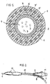
Figur 1- ein gemäß der Erfindung aufgebautes ADSS-Luftkabel im Querschnitt,
Figur 2- eine Vorrichtung zur Abspannung des ADSS-Luftkabels am Mast einer Hochspannungs-Freileitung,
Figur 3- ein zweites Ausführungsbeispiel eines ADSS-Luftkabels im Querschnitt und
Figur 4- ein erfindungsgemäßes ADL-Kabel im Querschnitt.
- Figure 1
- an ADSS air cable constructed according to the invention in cross section,
- Figure 2
- a device for tensioning the ADSS air cable on the mast of a high-voltage overhead line,
- Figure 3
- a second embodiment of an ADSS air cable in cross section and
- Figure 4
- an ADL cable according to the invention in cross section.
Grundelement des in Figur 1 nicht maßstabsgetreu dargestellten, selbsttragenden, rein dielektrischen Luftkabels 1 (ADSS-Kabel) ist die zentral angeordnete Maxibündelader 2 (Außendurchmesser ≈ 6 mm), deren als Schutzhülle für die 12 - 48 Lichtwellenleiter 3 (LWL) dienender Mantel aus einem extrudierbaren, vergleichsweise harten Kunststoff besteht. Als Hüllenmaterialien eignen sich insbesondere Polyamid (PA), Polypropylen (PP) und Polybutylentherephthalat (PBTP). Soll eine zweischichtige Schutzhülle zum Einsatz kommen, können deren Innenschicht beispielsweise aus Polycarbonat (PC), die aufextrudierte Außenschicht aus PBTP gefertigt sein.Basic element of the not shown to scale in Figure 1, self-supporting, purely dielectric air cable 1 (ADSS cable) is the centrally located maxi loose tube 2 (outer diameter ≈ 6 mm), whose protective cover for the 12 - 48 Optical waveguide 3 (LWL) serving jacket from an extrudable, comparatively hard plastic. As Shell materials are particularly suitable for polyamide (PA) and polypropylene (PP) and polybutylene terephthalate (PBTP). Should one two-layer protective cover can be used Inner layer made of polycarbonate (PC), for example extruded outer layer made of PBTP.
Die gegebenenfalls miteinander verseilten und jeweils aus einem
Glaskern (Brechungsindex nK), einem Glasmantel ("Cladding";
Brechungsindex nC < nK) und einer äußeren, üblicherweise
eingefärbten Lackschicht ("Coating"; Brechungsindex nCoa
> nK) bestehenden Lichtwellenleiter 3 sind mit Überlänge (≈ 5
‰) in der rohrförmigen Schutzhülle der Maxibündelader 2 angeordnet
und damit auch im abgespannten ADSS-Kabel 1 keinen
oder nur schwachen Zugkräften ausgesetzt. Eine chemisch neutrale,
im Temperaturbereich zwischen -40°C und +70°C nicht
tropfende oder gefrierende, leicht thixotrope Substanz 4 verhindert,
daß Wasser in die Bündelader 2 eindringen und sich
in Richtung der Kabellängsachse ausbreiten kann. The optical fibers optionally stranded together and each consisting of a glass core (refractive index n K ), a glass jacket ("cladding"; refractive index n C <n K ) and an outer, usually colored lacquer layer ("coating"; refractive index n Coa > n K ) 3 are arranged with excess length (≈ 5 ‰) in the tubular protective sheath of the maxi
Die auf das ADSS-Kabel 1 wirkenden Zugkräfte werden von den
symmetrisch bezüglich der Kabellängsachse angeordneten, im
Querschnitt elliptischen oder kreisförmigen und beispielsweise
aus gebündelten Aramidgarnen oder -fäden (Kevlar) bestehenden
Elementen 5/5' aufgenommen. Um deren Flexibilität
bzw. Biegbarkeit zu erhalten, muß der Kabelhersteller dafür
Sorge tragen, daß die Aramidgarne bzw. -fäden und das aufextrudierte
Mantelmaterial nicht miteinander verbacken. Anstelle
von Aramidgarnen lassen sich selbstverständlich auch
andere zugfeste Materialien, insbesondere Glasfasern (Rovings)
oder ultrahochmolekulare Polyolefinfasern (Handelsname
"Dynema") verwenden.The tensile forces acting on the
Der beispielsweise 1,7 mm dicke Außenmantel 6 des Luftkabels
1 besteht vorzugsweise aus Polyethylen (PE), insbesondere dem
mit Hilfe von Katalysatoren in einem speziellen Niederdruckverfahren
hergestellten LMDPE (Linear-Medium-Density-PE). Das
stark beanspruchte, der Witterung und intensiver Sonnenstrahlung
ausgesetzte PE enthält die üblichen Zusätze und Additive
wie Ruß, Antioxidationsmittel, Degradationshemmer, Pigmente
usw. in den für die jeweilige Anwendung erforderlichen Mengen
(siehe beispielsweise WO 99/04300).The 1.7 mm thick
Um die durch das elektrische Feld der Phasenseile im ADSS-Kabel
1 induzierten Ladungen über die auf Erdpotential liegenden,
am Mast befestigten Abspannspiralen (Figur 2) abzuleiten,
enthält der Außenmantel 6 mehrere, aus fertigungstechnischen
Gründen vorzugsweise parallel ausgerichtete und
symmetrisch bezüglich der Kabellängsachse angeordnete Schmelzefäden
7/7', deren elektrischer Widerstand im Bereich zwischen
105 Ω/m und 109 Ω/m liegt. Die Leitfähigkeit der aus
einem Polymer oder einer Polymermischung (Compound) bestehenden
Schmelzefäden 7/7' beruht im wesentlichen auf dem Gehalt
von Kohlenstoff bzw. Ruß, dessen Anteil an der Polymermatrix
10 Gew% bis max. 40 Gew% beträgt. Zu einer besonders innigen
und damit dauerhaften Verbindung zwischen dem als Mantelmaterial
dienenden PE und den darin vollständig eingebetteten, im
gezeigten Ausführungsbeispiel N = 20, jeweils 0,1 mm dicken
Schmelzefäden 7/7' kommt es, wenn auch die Schmelzefäden 7/7'
aus PE bestehen, bzw. PE mit ca. 50 - 90 Gew% die Hauptkomponente
der Polymermischung bildet. Durch den Zusatz von 0,1
Gew% Polyorganosiloxan ("Silikon") läßt sich die Temparaturbeständigkeit
der Schmelzefäden 7/7' verbessern. Außerdem
kann das Polymer oder die Polymermischung noch ein Antioxydationsmittel
(z.B. Irganox 1010) mit einem Anteil von 0,1 -
0,2 Gew% enthalten.In order to discharge the charges induced by the electrical field of the phase ropes in the
Die Einbettung der beispielsweise N = 2 - 100 und etwa 0,1 mm
- 1 mm dicken Schmelzefäden 7/7' in das noch schmelz- oder
zähflüssige Mantelmaterial erfolgt durch Anwendung der Technik
der Koextrusion unter Verwendung der in US 5,932,149 oder
US 5,360,497 beschriebenen Extruderköpfe. Die Anzahl der zu
erzeugenden Schmelzefäden 7/7' und deren Querschnittsfläche
sind hierbei so zu bemessen, daß eine sichere Ableitung der
induzierten Ladungen, also eine ausreichend hohe elektrische
Leitfähigkeit gewährleistet ist, der Außenmantel 6 als solcher
aber noch einen hohen elektrischen Widerstand von beispielsweise
1012 Ω/m in Kabellängsrichtung aufweist.The, for example, N = 2-100 and approximately 0.1 mm - 1 mm
In Tabelle 1 sind einige weitere, das ADSS-Kabel 1 kennzeichnenden
konstruktiven Merkmale und mechanische Daten angegeben:
Die Figur 2 zeigt eine Einrichtung zur Abspannung des ADSS-Kabels
1 am Mast einer Hochspannungsfreileitung. Sie besteht
aus der sog. Schutzspirale 8 mit einer Vielzahl, den Kabelmantel
wendelförmig eng umschlingenden Metalldrähten, der
ebenfalls aus Metall gefertigten, mastseitig in einen
schlauchförmigen Ansatz 9 übergehenden Abspannspirale 10 sowie
der den schlauchförmigen Ansatz 9 haltenden, am Mast befestigten
und damit auf Masse liegenden Kausche 11. Ein geerdeter,
der Feldsteuerung dienender Schrumpfschlauch 12 baut
Spannungsspitzen im Bereich des Übergangs von Luftkabel 1 zu
Abspannspirale 10 ab und verhindert damit Corona-Entladungen.
Der vorzugsweise aus einem halbleitenden Polyolefin-Compound
bestehende Schrumpfschlauch 12 ist kabelseitig mit einer
leitfähigen Schmelzkleberbeschichtung versehen. Die Dicke
dieser kabelseitigen Beschichtung ist hierbei so bemessen,
daß der beim Aufbringen des Schrumpfschlauches 12 erwärmte
und dadurch verflüssigte Schmelzkleber in die zwischen
Schrumpfschlauch 12, Schutzspirale 8 und ADSS-Kabel 1 vorhandenen
Hohlräume eindringt und diese vollständig ausfüllt. Der
Schrumpfschlauch 12 oder eine ebenfalls einsetzbare Schrumpfmanschette
reicht über das Ende der Schutzspirale 8 hinaus
und umschließt das ADSS-Kabel 1 noch auf einer Länge von mindestens
5 - 100 cm. Um das Abfließen der induzierten Ladungen
von den Schmelzefäden 7/7' zur Abspannspirale 10 zu erleichtern,
kann die Leitfähigkeit des Kabelmantels 6 durch einen
höheren Rußanteil verbessert werden.FIG. 2 shows a device for tensioning the
Das in Figur 3 im Querschnitt dargestellte ADSS-Kabel 1* unterscheidet
sich im wesentlichen nur im Aufbau seiner Seele
von dem oben beschriebenen Luftkabel 1. Diese besteht aus einem
zentralen Stützelement 13 (gegebenenfalls ummantelter
Stab aus glasfaserverstärkten Kunststoff), mehreren darauf
aufgeseilten Lichtwellenleiterhohl- oder Bündeladern 14 (Mantelmaterial
PBTP) mit jeweils N = 1 (Hohlader; Außendurchmesser
= 1,4 mm) bzw. N = 2 - 12 (Bündelader; Außendurchmesser
= 1,8 - 3,5 mm), in eine thixotrope Masse eingebetteten,
Ein- oder Mehrmoden Lichtwellenleiter 15 und einem rußgeschwärzten
PE-Innenmantel 16 bzw. einer Seelenbespinnung.
Mit 5/5' sind wieder die die Zugkräfte aufnehmenden Aramidgarne,
mit 6 der MDPE-Außenmantel und mit 7/7' die durch Koextrusion
in das Mantelmaterial eingebetteten, Kohlenstoff
bzw. Ruß enthaltenden Schmelzefäden bezeichnet.The
Die Figur 4 zeigt ein erfindungsgemäßes ADL-Kabel 21 im Querschnitt.
Es besteht aus der schon erwähnten Maxibündelader 2,
den beiden diagonal gegenüberliegend angeordneten Zugentlastungselementen
17/17' (Aramidgarne) und einem PE-Außenmantel
18 mit den darin eingebetteten, kohlenstoffhaltigen Schmelzefäden
19/19'. Einige weitere, das ADL-Kabel 21 charakterisierenden
konstruktiven Merkmale und mechanische Daten sind in
Tabelle 2 angegeben.
Die Erfindung beschränkt sich selbstverständlich nicht auf die oben beschriebenen Ausführungsbeispiele. So sind folgende Ausgestaltungen und Weiterbildungen ohne weiteres möglich,
- den Außenmantel des Kabels nicht aus PE (LDPE, MDPE, LDPE, LLDPE), sondern aus Polypropylen (PP), Copolymeren des Propylens mit einem anderen Olefin oder Ethylen - Vinylazetat (EVA) zu fertigen,
- die halbleitenden Schmelzefäden spiralförmig längs der Ka belachse verlaufend in den Kabelmantel einzubetten,
- das PE-Compound LE 0563 der Firma Borealis Deutschland GmbH als Material für die halbleitenden Schmelzefäden zu verwenden,
- die halbleitenden Schmelzfäden aus 10 - 40 Gew% Kohlenstoff oder Ruß enthaltendem PP zu fertigen
- mehrere, konzentrisch bezüglich der Kabellängsachse angeordnete Lagen von halbleitenden Schmelzefäden im Außenmantel vorzusehen,
- die Lichtwellenleiter in den Bündeladern zu verseilen,
- LWL-Bändchen, d.h. mehrere, insbesondere bis zu 16 parallel ausgerichtete und durch eine äußere Hülle mechanisch zusammengehaltene LWL oder LWL-Bändchen stapelförmig in den gefüllten oder ungefüllten Bündeladern anzuordnen,
- mehrere Lagen von Bündel- oder Hohladern auf das Zentralelement aufzuseilen und
- ein mehrere, jeweils nach Außen offene, spiral- oder wendelförmig umlaufende Kammern aufweisendes Zentralelement in der Kabelseele vorzusehen ("Kammerkabel").
- not to manufacture the outer sheath of the cable from PE (LDPE, MDPE, LDPE, LLDPE), but from polypropylene (PP), copolymers of propylene with another olefin or ethylene-vinyl acetate (EVA),
- to embed the semiconducting melt threads in a spiral along the cable axis in the cable sheath,
- to use the PE compound LE 0563 from Borealis Deutschland GmbH as material for the semiconducting melt threads,
- to manufacture the semiconducting melting threads from PP containing 10-40% by weight of carbon or carbon black
- to provide a plurality of layers of semiconducting melt threads arranged concentrically with respect to the longitudinal axis of the cable in the outer jacket,
- to strand the optical fibers in the loose tubes,
- LWL tapes, ie several, in particular up to 16 parallel aligned and mechanically held together by an outer sleeve LWL or LWL tapes to be stacked in the filled or unfilled loose tubes,
- to rope several layers of bundle or hollow veins onto the central element and
- to provide a central element in the cable core which has a plurality of, in each case open to the outside, spiral or helical circumferential chambers ("chamber cable").
Claims (15)
dadurch gekennzeichnet, daß die strang- oder fadenförmigen Elemente (7/7', 19/19') gleichzeitig mit dem Außenmantel (6) durch Koextrussion hergestellt sind.Air cable according to claim 1,
characterized in that the strand or thread-like elements (7/7 ', 19/19') are produced simultaneously with the outer jacket (6) by coextrusion.
dadurch gekennzeichnet, daß die halbleitenden Eigenschaften des Polymers oder der Polymermischung auf dem Zusatz von Kohlenstoff oder Ruß beruhen.Air cable according to claim 1 or 2,
characterized in that the semiconducting properties of the polymer or the polymer mixture are based on the addition of carbon or carbon black.
dadurch gekennzeichnet, daß der Anteil des Kohlenstoffs oder des Rußes in der Polymermatrix 10 Gew.% bis maximal 40 Gew.% beträgt.Air cable according to claim 3,
characterized in that the proportion of carbon or carbon black in the polymer matrix is 10% by weight to a maximum of 40% by weight.
dadurch gekennzeichnet, daß dem Polymer oder die Polymermischung Polyorganosiloxan beigemischt ist. Air cable according to one of claims 1 to 4,
characterized in that the polymer or the polymer mixture is mixed with polyorganosiloxane.
dadurch gekennzeichnet, daß die strang- oder fadenförmigen Elemente (7/7', 19/19') zu mehr als 50 Gew.% aus PE oder PP bestehen.Air cable according to one of claims 1 to 5,
characterized in that the strand or thread-like elements (7/7 ', 19/19') consist of more than 50% by weight of PE or PP.
dadurch gekennzeichnet, daß die strang- oder fadenförmigen Elemente (7/7', 19/19') parallel ausgerichtet und symmetrisch bezüglich der Längsachse des Luftkabels im Außenmantel (6) angeordnet sind.Air cable according to one of claims 1 to 6,
characterized in that the strand-like or thread-like elements (7/7 ', 19/19') are aligned in parallel and arranged symmetrically with respect to the longitudinal axis of the air cable in the outer jacket (6).
dadurch gekennzeichnet, daß die faden- oder strangförmigen Elemente (7/7', 19/19') radial in der Mitte des Außenmantels (6) angeordnet sind.Air cable according to claim 7,
characterized in that the thread-like or strand-like elements (7/7 ', 19/19') are arranged radially in the middle of the outer casing (6).
dadurch gekennzeichnet, daß der Durchmesser der strang- oder fadenförmigen Elemente (7/7', 19/19') im Bereich von 0,01 mm bis 1 mm liegt und deren Anzahl N = 1 bis 100, vorzugsweise N = 2 - 50 beträgt.Air cable according to one of claims 1 to 8,
characterized in that the diameter of the strand-like or thread-like elements (7/7 ', 19/19') is in the range from 0.01 mm to 1 mm and their number is N = 1 to 100, preferably N = 2-50 .
dadurch gekennzeichnet, daß der Außenmantel (6) aus einem Polyolefin oder Copolymeren verschiedener Olefine besteht.Air cable according to one of claims 1 to 9,
characterized in that the outer jacket (6) consists of a polyolefin or copolymers of different olefins.
dadurch gekennzeichnet, daß der Außenmantel (6) aus HDPE, MDPE, LDPE, LLDPE, PP oder EVA besteht.Air cable according to claim 10,
characterized in that the outer jacket (6) consists of HDPE, MDPE, LDPE, LLDPE, PP or EVA.
dadurch gekennzeichnet, daß das optische Übertragungselement (3) mit Überlänge in der rohrförmigen Schutzhülle (2, 14) angeordnet ist. Air cable according to one of claims 1 to 11,
characterized in that the optical transmission element (3) with excess length is arranged in the tubular protective cover (2, 14).
dadurch gekennzeichnet, daß die Schutzhülle (2, 14) mit einer gelartigen, thixotrope Eigenschaften aufweisenden Substanz oder Masse gefüllt ist.Air cable according to one of claims 1 to 12,
characterized in that the protective cover (2, 14) is filled with a gel-like substance or mass having thixotropic properties.
dadurch gekennzeichnet, daß mehrere zugfeste Elemente (5/5', 17/17') zwischen der Schutzhülle (2) und dem Außenmantel (6) symmetrisch bezüglich der Kabellängsachse angeordnet sind.Air cable according to one of claims 1 to 13,
characterized in that several tensile elements (5/5 ', 17/17') are arranged symmetrically with respect to the longitudinal axis of the cable between the protective sheath (2) and the outer jacket (6).
Applications Claiming Priority (2)
| Application Number | Priority Date | Filing Date | Title |
|---|---|---|---|
| DE10028562A DE10028562A1 (en) | 2000-06-09 | 2000-06-09 | Air cable containing optical transmission elements and method of manufacturing an air cable |
| DE10028562 | 2000-06-09 |
Publications (2)
| Publication Number | Publication Date |
|---|---|
| EP1162488A2 true EP1162488A2 (en) | 2001-12-12 |
| EP1162488A3 EP1162488A3 (en) | 2004-03-03 |
Family
ID=7645225
Family Applications (1)
| Application Number | Title | Priority Date | Filing Date |
|---|---|---|---|
| EP01112747A Withdrawn EP1162488A3 (en) | 2000-06-09 | 2001-05-25 | Optical fiber aerial cable and manufacturing method |
Country Status (3)
| Country | Link |
|---|---|
| US (1) | US6519396B2 (en) |
| EP (1) | EP1162488A3 (en) |
| DE (1) | DE10028562A1 (en) |
Families Citing this family (43)
| Publication number | Priority date | Publication date | Assignee | Title |
|---|---|---|---|---|
| US6845789B2 (en) * | 2001-11-30 | 2005-01-25 | Corning Cable Systems Llc | High density fiber optic cable inner ducts |
| US20040184749A1 (en) * | 2003-03-20 | 2004-09-23 | Herbst Brian G. | Fiber optic cable and method of manufacturing same |
| DE10355308A1 (en) * | 2003-11-27 | 2005-07-07 | CCS Technology, Inc., Wilmington | Cap, assembly and method for fastening and / or sealing an optical transmission element |
| US7822306B2 (en) * | 2007-01-08 | 2010-10-26 | Commscope, Inc. Of North Carolina | Buoyancy neutral fiber optic cable |
| US7489844B2 (en) * | 2007-01-08 | 2009-02-10 | Commscope, Inc. Of North Carolina | Ruggedized deep-sea rov deployment cable |
| WO2010104538A1 (en) | 2009-03-02 | 2010-09-16 | Coleman Cable, Inc. | Flexible cable having a dual layer jacket |
| US8885999B2 (en) * | 2010-03-19 | 2014-11-11 | Corning Cable Systems Llc | Optical USB cable with controlled fiber positioning |
| JP6017415B2 (en) | 2010-04-30 | 2016-11-02 | コーニング オプティカル コミュニケイションズ リミテッド ライアビリティ カンパニー | Optical fiber cable with access feature and method of manufacturing the same |
| RU142326U1 (en) | 2010-10-28 | 2014-06-27 | КОРНИНГ КЭЙБЛ СИСТЕМЗ ЭлЭлСи | FIBER OPTICAL CABLES WITH EXTRUDED ACCESS ELEMENTS AND METHODS FOR MANUFACTURING FIBER OPTICAL CABLES |
| ES2955526T3 (en) | 2010-11-23 | 2023-12-04 | Corning Optical Communications LLC | Fiber optic cables with access characteristics and manufacturing method |
| AU2012212429A1 (en) * | 2011-01-31 | 2013-08-15 | Afl Telecommunications Llc | All-dielectric self-supporting (ADSS) fiber optic cable with a semi-conducting co-extruded tracking resistant jacket |
| EP2718758B1 (en) | 2011-06-10 | 2015-08-12 | Corning Cable Systems LLC | Fiber optic cables allowing fiber translation to reduce bend attenuation |
| US9274302B2 (en) | 2011-10-13 | 2016-03-01 | Corning Cable Systems Llc | Fiber optic cables with extruded access features for access to a cable cavity |
| US8682124B2 (en) | 2011-10-13 | 2014-03-25 | Corning Cable Systems Llc | Access features of armored flat fiber optic cable |
| US9323022B2 (en) | 2012-10-08 | 2016-04-26 | Corning Cable Systems Llc | Methods of making and accessing cables having access features |
| US9201208B2 (en) | 2011-10-27 | 2015-12-01 | Corning Cable Systems Llc | Cable having core, jacket and polymeric jacket access features located in the jacket |
| US9176293B2 (en) | 2011-10-28 | 2015-11-03 | Corning Cable Systems Llc | Buffered fibers with access features |
| US8676012B2 (en) | 2012-01-20 | 2014-03-18 | Corning Cable Systems Llc | Fiber optic cable for very-short-distance networks |
| US8620123B2 (en) * | 2012-02-13 | 2013-12-31 | Corning Cable Systems Llc | Visual tracer system for fiber optic cable |
| US8909014B2 (en) | 2012-04-27 | 2014-12-09 | Corning Cable Systems Llc | Fiber optic cable with access features and jacket-to-core coupling, and methods of making the same |
| US9170389B2 (en) | 2012-08-28 | 2015-10-27 | Corning Cable Systems Llc | Hybrid fiber optic cable systems |
| US9482839B2 (en) | 2013-08-09 | 2016-11-01 | Corning Cable Systems Llc | Optical fiber cable with anti-split feature |
| US9429731B2 (en) | 2013-08-12 | 2016-08-30 | Corning Optical Communications LLC | Optical fiber cable assembly comprising optical tracer fiber |
| JP5719052B1 (en) * | 2014-03-06 | 2015-05-13 | 株式会社フジクラ | Optical cable |
| BR112017004119B1 (en) * | 2014-09-25 | 2022-03-15 | Draka Comteq B.V. | optical cable |
| US10379309B2 (en) | 2014-11-18 | 2019-08-13 | Corning Optical Communications LLC | Traceable optical fiber cable and filtered viewing device for enhanced traceability |
| US10228526B2 (en) | 2015-03-31 | 2019-03-12 | Corning Optical Communications LLC | Traceable cable with side-emitting optical fiber and method of forming the same |
| US10101553B2 (en) | 2015-05-20 | 2018-10-16 | Corning Optical Communications LLC | Traceable cable with side-emitting optical fiber and method of forming the same |
| EP3325876A1 (en) | 2015-07-17 | 2018-05-30 | Corning Optical Communications LLC | Systems and methods for traceable cables |
| CN107850737A (en) | 2015-07-17 | 2018-03-27 | 康宁光电通信有限责任公司 | For tracking the system and method for cable and cable for such system and method |
| US10101545B2 (en) | 2015-10-30 | 2018-10-16 | Corning Optical Communications LLC | Traceable cable assembly and connector |
| CN109154702A (en) | 2016-04-08 | 2019-01-04 | 康宁光电通信有限责任公司 | Traceable endpoint CA cable assembly |
| US10107983B2 (en) | 2016-04-29 | 2018-10-23 | Corning Optical Communications LLC | Preferential mode coupling for enhanced traceable patch cord performance |
| US10222560B2 (en) | 2016-12-21 | 2019-03-05 | Corning Research & Development Corporation | Traceable fiber optic cable assembly with fiber guide and tracing optical fibers for carrying light received from a light launch device |
| CN106772855B (en) * | 2016-12-28 | 2023-09-05 | 国网浙江省电力公司湖州供电公司 | ADSS optical cable line protection device for preventing animal damage |
| US10234614B2 (en) | 2017-01-20 | 2019-03-19 | Corning Research & Development Corporation | Light source assemblies and systems and methods with mode homogenization |
| JP7074124B2 (en) * | 2017-03-21 | 2022-05-24 | 住友電気工業株式会社 | Fiber optic cable |
| JP6927760B2 (en) * | 2017-06-23 | 2021-09-01 | 三菱電線工業株式会社 | Optical fiber core wire protection structure |
| US20190080819A1 (en) * | 2017-09-12 | 2019-03-14 | General Cable Technologies Corporation | Low-smoke, halogen-free flexible cords |
| US10539747B2 (en) | 2017-12-05 | 2020-01-21 | Corning Research & Development Corporation | Bend induced light scattering fiber and cable assemblies and method of making |
| US10539758B2 (en) | 2017-12-05 | 2020-01-21 | Corning Research & Development Corporation | Traceable fiber optic cable assembly with indication of polarity |
| US10120152B1 (en) | 2018-02-13 | 2018-11-06 | Superior Essex International LP | All dielectric self-supporting fiber optic cable |
| US20220146563A1 (en) * | 2019-03-06 | 2022-05-12 | Ctc Global Corporation | Overhead electrical cable interrogation systems and methods |
Citations (5)
| Publication number | Priority date | Publication date | Assignee | Title |
|---|---|---|---|---|
| US4645298A (en) * | 1983-07-28 | 1987-02-24 | At&T Bell Laboratories | Optical fiber cable |
| US4776665A (en) * | 1985-08-12 | 1988-10-11 | Siemens Aktiengesellschaft | Metal-free, self-bearing optical cable for high-tension overhead lines |
| GB2240189A (en) * | 1990-01-17 | 1991-07-24 | Telephone Cables Ltd | Optical cables |
| DE19605276A1 (en) * | 1996-02-13 | 1997-08-14 | Siemens Ag | Method and device for manufacturing an optical cable |
| EP0660149B1 (en) * | 1993-12-17 | 2000-08-23 | Corning Communications Limited | Optical cable with semiconductive component |
Family Cites Families (11)
| Publication number | Priority date | Publication date | Assignee | Title |
|---|---|---|---|---|
| DD110905A1 (en) | 1973-10-12 | 1975-01-12 | ||
| DD153616A1 (en) | 1980-10-15 | 1982-01-20 | Rolf Arnold | ROLLING PRODUCT AND METHOD FOR THE PRODUCTION THEREOF |
| DE3113528C2 (en) | 1981-04-02 | 1983-05-05 | Siemens AG, 1000 Berlin und 8000 München | Device for wrapping stranding elements of electrical and / or optical cables |
| US4557560A (en) * | 1983-11-15 | 1985-12-10 | At&T Technologies, Inc. | Rodent and lightning protective sheath system for cables |
| DE3504041A1 (en) * | 1984-06-29 | 1986-01-02 | Siemens AG, 1000 Berlin und 8000 München | OPTICAL CABLE FOR HIGH VOLTAGE LEADERS |
| DE3618659C2 (en) * | 1986-06-03 | 1997-04-10 | Rheydt Kabelwerk Ag | Metal-free aerial cable with fiber optic wires |
| US5018825A (en) * | 1989-06-14 | 1991-05-28 | Bicc Public Limited Company | Overhead optical transmission system |
| DE4142047C2 (en) * | 1991-12-19 | 2001-03-01 | Siemens Ag | Method for covering at least one optical waveguide with a protective layer and for attaching reinforcing elements |
| GB9308361D0 (en) | 1993-04-22 | 1993-06-09 | Bicc Plc | Optical cable |
| DE19546773B4 (en) | 1995-02-20 | 2006-01-12 | CCS Technology, Inc., Wilmington | Method and device for longitudinally applying at least one elongate retaining element to a continuous bundle |
| CA2296361C (en) * | 1997-07-18 | 2008-09-30 | Pirelli Cavi E Sistemi S.P.A. | Optical fibre cable having high tracking resistance |
-
2000
- 2000-06-09 DE DE10028562A patent/DE10028562A1/en not_active Withdrawn
-
2001
- 2001-05-25 EP EP01112747A patent/EP1162488A3/en not_active Withdrawn
- 2001-06-08 US US09/877,722 patent/US6519396B2/en not_active Expired - Fee Related
Patent Citations (5)
| Publication number | Priority date | Publication date | Assignee | Title |
|---|---|---|---|---|
| US4645298A (en) * | 1983-07-28 | 1987-02-24 | At&T Bell Laboratories | Optical fiber cable |
| US4776665A (en) * | 1985-08-12 | 1988-10-11 | Siemens Aktiengesellschaft | Metal-free, self-bearing optical cable for high-tension overhead lines |
| GB2240189A (en) * | 1990-01-17 | 1991-07-24 | Telephone Cables Ltd | Optical cables |
| EP0660149B1 (en) * | 1993-12-17 | 2000-08-23 | Corning Communications Limited | Optical cable with semiconductive component |
| DE19605276A1 (en) * | 1996-02-13 | 1997-08-14 | Siemens Ag | Method and device for manufacturing an optical cable |
Also Published As
| Publication number | Publication date |
|---|---|
| US20020041743A1 (en) | 2002-04-11 |
| US6519396B2 (en) | 2003-02-11 |
| EP1162488A3 (en) | 2004-03-03 |
| DE10028562A1 (en) | 2001-12-13 |
Similar Documents
| Publication | Publication Date | Title |
|---|---|---|
| EP1162488A2 (en) | Optical fiber aerial cable and manufacturing method | |
| DE69325046T2 (en) | Hybrid communication cable to improve the transmission capacity | |
| EP0874262A2 (en) | Optical cable and method of manufacturing an optical cable | |
| DE3518909A1 (en) | STRONG POWER CABLE, ESPECIALLY FOR VOLTAGES FROM 6 TO 60 KV, WITH INSERTED FOCUS | |
| DE9013175U1 (en) | Electro-optical overhead cable with 24 or more optical fibers | |
| EP0834755A2 (en) | Optical cable or element | |
| DE2815563A1 (en) | OPTICAL CABLE | |
| DE3232108A1 (en) | Optical cable | |
| DE3023669C2 (en) | Self-supporting optical communication cable | |
| DE3538664C2 (en) | ||
| EP1970487B1 (en) | Funicular support rope | |
| DE4416545A1 (en) | Cable with electrical and optical conductors | |
| EP0992826A2 (en) | Anchorable cable for installation in a drainage or pipe system | |
| DE2847384A1 (en) | High tension proof optical communication cable - with polyurethane epoxy! or polyester filling and sheath of polyethylene, polypropylene, polyurethane or polyester | |
| WO2011035450A2 (en) | Electro-optical cable | |
| EP0509299B1 (en) | Optical cable | |
| DE29518024U1 (en) | Communication cable | |
| EP1024381A1 (en) | Optical cable for use along high voltage overhead lines | |
| DE9321083U1 (en) | Power transmission cable with fiber optic element | |
| DE3606589C2 (en) | ||
| DE102021131881B4 (en) | Internal metal-free armored fiber optic cable | |
| DE2841828A1 (en) | Optical fibre communications cable - has a plastic mass to fill hollow zone in cable | |
| DE202005008731U1 (en) | Hybrid cable e.g. telecommunications cable with copper and optical elements, has number of stranding elements twisted around power supply cable | |
| EP0666576B1 (en) | Power cable | |
| DE4333827C2 (en) | Power transmission cable with fiber optic element |
Legal Events
| Date | Code | Title | Description |
|---|---|---|---|
| PUAI | Public reference made under article 153(3) epc to a published international application that has entered the european phase |
Free format text: ORIGINAL CODE: 0009012 |
|
| AK | Designated contracting states |
Kind code of ref document: A2 Designated state(s): AT BE CH CY DE DK ES FI FR GB GR IE IT LI LU MC NL PT SE TR |
|
| AX | Request for extension of the european patent |
Free format text: AL;LT;LV;MK;RO;SI |
|
| PUAL | Search report despatched |
Free format text: ORIGINAL CODE: 0009013 |
|
| AK | Designated contracting states |
Kind code of ref document: A3 Designated state(s): AT BE CH CY DE DK ES FI FR GB GR IE IT LI LU MC NL PT SE TR |
|
| AX | Request for extension of the european patent |
Extension state: AL LT LV MK RO SI |
|
| STAA | Information on the status of an ep patent application or granted ep patent |
Free format text: STATUS: THE APPLICATION IS DEEMED TO BE WITHDRAWN |
|
| 18D | Application deemed to be withdrawn |
Effective date: 20031202 |