EP0874262A2 - Optical cable and method of manufacturing an optical cable - Google Patents
Optical cable and method of manufacturing an optical cable Download PDFInfo
- Publication number
- EP0874262A2 EP0874262A2 EP98400795A EP98400795A EP0874262A2 EP 0874262 A2 EP0874262 A2 EP 0874262A2 EP 98400795 A EP98400795 A EP 98400795A EP 98400795 A EP98400795 A EP 98400795A EP 0874262 A2 EP0874262 A2 EP 0874262A2
- Authority
- EP
- European Patent Office
- Prior art keywords
- optical cable
- tubular
- outer layer
- tubular sheath
- inner layer
- Prior art date
- Legal status (The legal status is an assumption and is not a legal conclusion. Google has not performed a legal analysis and makes no representation as to the accuracy of the status listed.)
- Withdrawn
Links
Images


Classifications
-
- G—PHYSICS
- G02—OPTICS
- G02B—OPTICAL ELEMENTS, SYSTEMS OR APPARATUS
- G02B6/00—Light guides; Structural details of arrangements comprising light guides and other optical elements, e.g. couplings
- G02B6/46—Processes or apparatus adapted for installing or repairing optical fibres or optical cables
- G02B6/48—Overhead installation
- G02B6/483—Installation of aerial type
-
- G—PHYSICS
- G02—OPTICS
- G02B—OPTICAL ELEMENTS, SYSTEMS OR APPARATUS
- G02B6/00—Light guides; Structural details of arrangements comprising light guides and other optical elements, e.g. couplings
- G02B6/44—Mechanical structures for providing tensile strength and external protection for fibres, e.g. optical transmission cables
- G02B6/4401—Optical cables
- G02B6/4429—Means specially adapted for strengthening or protecting the cables
- G02B6/443—Protective covering
- G02B6/4432—Protective covering with fibre reinforcements
-
- G—PHYSICS
- G02—OPTICS
- G02B—OPTICAL ELEMENTS, SYSTEMS OR APPARATUS
- G02B6/00—Light guides; Structural details of arrangements comprising light guides and other optical elements, e.g. couplings
- G02B6/44—Mechanical structures for providing tensile strength and external protection for fibres, e.g. optical transmission cables
- G02B6/4479—Manufacturing methods of optical cables
Abstract
Description
Die Erfindung betrifft ein optisches Kabel mit wenigstens einer optischen Faser, die von einer eine innere Schicht und eine äußere Schicht aufweisenden und in einem Arbeitsschritt extrudierten rohrförmigen Hülle umschlossen ist, bzw. ein Verfahren zum Herstellen eines wenigstens eine von einer rohrförmigen Hülle umschlossene optische Faser aufweisenden optischen Kabels, bei dem eine innere Schicht und eine äußere Schicht der rohrförmigen Hülle in einem Arbeitsschritt gemeinsam um die optische Faser extrudiert werden.The invention relates to an optical cable with at least an optical fiber consisting of an inner layer and an outer layer and in one step extruded tubular shell is enclosed, or a Method of making at least one of one having tubular casing enclosed optical fiber optical cable, with an inner layer and an outer Layer of tubular casing in one step extruded together around the optical fiber.
Optische Fasern reagieren auf Dehnungs-, Biege- und Torsionsbeanspruchungen mit einer Dämpfungserhöhung. Darüber hinaus weisen sie eine relativ niedrige Bruchdehnung auf, so daß es schon bei vergleichsweise geringen mechanischen Beanspruchungen der optischen Fasern zu Schäden kommen kann. Es ist daher für den Einsatz von optischen Fasern in Kabeln unbedingt erforderlich, die optischen Fasern weitgehend frei von äußeren Einflüssen zu halten, indem sie von einer geeigneten Umhüllung umschlossen sind. So ist es bekannt, eine oder mehrere optische Fasern in einer durch ein Kunststoffröhrchen gebildeten rohrförmigen Hülle unterzubringen. Derartige rohrförmige Hüllen müssen eine ausreichende mechanische Festigkeit und eine gute Alterungsbeständigkeit aufweisen und dabei vergleichsweise flexibel sein. Um diesen Anforderungen gerecht zu werden, werden zweischichtige Kunststoffröhrchen verwendet, die aus einer inneren Schicht mit einem sehr niedrigen Reibungskoeffizienten und einer äußeren, mechanisch stabilen und alterungsbeständigen Schicht bestehen. Solche zweischichtigen rohrförmigen Hüllen werden üblicherweise in einem kontinuierlichen Prozeß mittels zwei hintereinander angeordneten Extrudern hergestellt. Zur Vereinfachung der Fertigung ist es ebenfalls bekannt, die beiden Schichten einer eine oder mehrere optische Fasern lose umschließenden zweischichtigen rohrförmigen Hülle in einem einzigen Arbeitsschritt mittels einer sogenannten Co-Extrusion in einer einzigen Extrusionseinrichtung herzustellen. Um bei einer eventuellen Beschädigung einer solchen optischen Hohl- oder Bündelader ein Entlangwandern von Wasser oder einer anderen Flüssigkeit innerhalb der rohrförmigen Hülle zu vermeiden, kann die rohrförmige Hülle mit einer geeigneten thixotropen Masse gefüllt sein.Optical fibers react to stretching, bending and Torsional stresses with an increase in damping. About that they also have a relatively low elongation at break, so that it is already at comparatively low mechanical Strains on the optical fibers can lead to damage. It is therefore for the use of optical fibers in cables absolutely necessary, the optical fibers largely free from external influences by being from a suitable wrapping are enclosed. So it is known one or more optical fibers in one by one Plastic tube formed tubular shell to accommodate. Such tubular casings must be one sufficient mechanical strength and good Have aging resistance and comparatively to be flexible. To meet these requirements, two-layer plastic tubes are used, which are made of an inner layer with a very low one Friction coefficient and an outer, mechanically stable and aging-resistant layer. Such two-layer tubular casings are commonly used in a continuous process using two in a row arranged extruders manufactured. To simplify the It is also known to manufacture the two layers of one loosely enclosing one or more optical fibers two-layer tubular casing in a single Working step by means of a so-called co-extrusion in one manufacture single extrusion device. To at one possible damage to such an optical hollow or Loose tube a migration of water or another To avoid liquid within the tubular envelope can the tubular shell with a suitable thixotropic Mass be filled.
Für die unterschiedlichen Verwendungszwecke und Installationsarten von optischen Kabeln sind die verschiedensten Kabelaufbauten bekannt. So ist beispielsweise in telcom report 17 (1994), Heft 4, Seiten 170 bis 172, ein Luftkabel dargestellt, das über einer zentralen Bündelader, die durch eine eine Mehrzahl von optischen Fasern aufweisende rohrförmige Hülle gebildet ist, eine Aramidgarnbewicklung zur Zugentlastung des Kabels sowie einen Außenmantel aufweist. Die Aramidgarnbewicklung und der Außenmantel führen dabei zu einem gegenüber dem Durchmesser der Bündelader wesentlich vergrößerten Durchmesser des Kabels.For the different uses and Types of installation of optical cables are various cable structures known. For example in telcom report 17 (1994), volume 4, pages 170 to 172 Aerial cable shown above a central loose tube, that by a plurality of optical fibers tubular sheath is formed, an aramid yarn winding Strain relief of the cable and an outer jacket. The Aramid yarn winding and the outer jacket lead to one compared to the diameter of the loose tube enlarged diameter of the cable.
Ausgehend von diesem Stand der Technik liegt der Erfindung das Problem zugrunde, ein optisches Kabel zu schaffen, das einen kleinen Außendurchmesser und ein geringes Gewicht aufweist und das die vor mechanischen Beanspruchungen wirkungsvoll geschützte Unterbringung einer Vielzahl von optischen Fasern ermöglicht.Based on this prior art, the invention is Problem to create an optical cable that one has small outer diameter and light weight and effective against mechanical stress protected housing of a variety of optical fibers enables.
Dieses Problem wird durch die Erfindung gelöst, indem in der rohrförmigen Hülle zugfeste Elemente eingebettet sind, bzw. bei der Extrusion der inneren Schicht und der äußeren Schicht zugfeste Elemente in die rohrförmige Hülle eingebracht werden.This problem is solved by the invention in that tubular casing tensile elements are embedded, or in the extrusion of the inner layer and the outer layer tensile elements are introduced into the tubular shell.
Die durch die Erfindung erzielbaren Vorteile bestehen insbesondere darin, daß das lediglich aus der einzigen rohrförmigen Hülle und in dieser verlaufenden optischen Fasern bestehende optische Kabel durch den Verzicht auf eine auf die rohrförmige Hülle aufgebrachte Bewehrung und auf einen darüber angeordneten Außenmantel einen kleinen Außendurchmesser und ein geringes Gewicht je Längeneinheit aufweist. Selbst bei einem sehr kleinen Außendurchmesser der rohrförmigen Hülle kann eine Vielzahl von optischen Fasern in dem optischen Kabel untergebracht werden. Die in der rohrförmigen Hülle des Kabels eingebetteten zugfesten Elemente gewährleisten eine ausreichende Zugentlastung der optischen Fasern. Das erfindungsgemäße optische Kabel eignet sich als Innenraumkabel, insbesondere aber auch als nichtselbsttragendes Luftkabel zur Installation an einem Tragseil wie z. B. einem Erdseil oder einem Phasenseil einer Hochspannungsfreileitung. In dem letztgenannten Anwendungsfall sind das geringe Gewicht und der geringe Außendurchmesser des optischen Kabels für eine einfache und kostengünstige Installation von besonderem Vorteil, da mit den bekannten Verlege- und Installationsvorrichtungen sehr große Lauflängen des optischen Kabels an einem an Masten aufgehängten Tragseil installiert werden können. Darüber hinaus ist das erfindungsgemäße optische Kabel einfach und kostengünstig herstellbar.The advantages that can be achieved by the invention exist especially in the fact that it's just the only one tubular shell and optical fibers running in it existing optical cables by dispensing with one tubular reinforcement applied to and over one arranged outer jacket a small outer diameter and has a low weight per unit length. Even at a very small outer diameter of the tubular casing can have a variety of optical fibers in the optical cable be accommodated. The one in the tubular sheath of the cable embedded tensile elements ensure a sufficient strain relief for the optical fibers. The Optical cable according to the invention is suitable as Indoor cable, but especially as non-self-supporting aerial cable for installation on one Suspension rope such. B. a ground rope or a phase rope Power transmission line. In the latter application are the low weight and the small outside diameter of the optical cable for easy and inexpensive Installation of particular advantage, as with the known Laying and installation devices very long run lengths of the optical cable on a suspension cable suspended from masts can be installed. Beyond that it is optical cable according to the invention simple and inexpensive producible.
Durch die in den Unteransprüchen aufgeführten Merkmale sind vorteilhafte Weiterbildungen und Verbesserungen der Erfindung möglich.By the features listed in the subclaims advantageous developments and improvements of the invention possible.
Für eine einfache Einbringung der zugfesten Elemente in die rohrförmige Hülle des durch die einzige rohrförmige Hülle und in dieser verlaufende optische Fasern gebildeten optischen Kabels und eine wirkungsvolle Zugentlastung der optischen Fasern ist es von Vorteil, wenn die zugfesten Elemente im Bereich zwischen der inneren Schicht und der äußeren Schicht in die rohrförmige Hülle eingebracht werden. Dabei wird die Zugfestigkeit der beiden Schichten der rohrförmigen Hülle in gleichem Maße verbessert.For easy insertion of the tensile elements in the tubular envelope of the through the only tubular envelope and optical fibers formed in this extending optical fibers Cable and an effective strain relief of the optical Fibers, it is advantageous if the tensile elements in the Area between the inner layer and the outer layer be introduced into the tubular casing. The Tensile strength of the two layers of tubular casing in improved to the same extent.
Vorteilhaft ist es ebenfalls, wenn zugfeste Elemente in die äußere Schicht der rohrförmigen Hülle eingebracht werden.It is also advantageous if tensile elements in the outer layer of the tubular shell are introduced.
Wird das optische Kabel an einem Phasenseil oder Erdseil einer Hochspannungsfreileitung installiert, so ist es von Vorteil, wenn die innere Schicht der rohrförmigen Hülle aus einem hochtemperaturfesten Kunststoff ausgebildet ist, der eine Schmelztemperatur von zumindest 160°C aufweist, so daß die rohrförmige Hülle auch bei höheren thermischen Belastungen einen zuverlässigen mechanischen Schutz der optischen Fasern gewährleistet.If the optical cable is connected to a phase cable or earth cable High-voltage overhead line installed, so it is advantageous if the inner layer of the tubular shell is made of a high temperature resistant plastic is formed, the one Has melting temperature of at least 160 ° C, so that the tubular casing even with higher thermal loads reliable mechanical protection of the optical fibers guaranteed.
Um diesen Anforderungen zu genügen, ist es von Vorteil, wenn die innere Schicht der rohrförmigen Hülle aus einem Polyamid ausgebildet ist. Polyamide haben zudem den Vorteil einer glatten Oberfläche, so daß die Gefahr einer Beschädigung einer optischen Faser bei der Berührung der inneren Wandung der rohrförmigen Hülle vermieden ist.In order to meet these requirements, it is advantageous if the inner layer of the tubular shell made of a polyamide is trained. Polyamides also have the advantage of one smooth surface, so that the risk of damage to a optical fiber when touching the inner wall of the tubular shell is avoided.
Die äußere Schicht der rohrförmigen Hülle des erfindungsgemäßen optischen Kabels, der als äußerste Schicht des Kabels zugleich die Funktion eines Außenmantels zukommt, ist vorzugsweise aus einem gegen UV-Licht und Chemikalien beständigen und eine hohe mechanische Festigkeit aufweisenden Kunststoff ausgebildet. Bei der Installation des optischen Kabels an einem Phasen- oder Erdseil einer Hochspannungsfreileitung ist es besonders vorteilhaft, wenn die äußere Schicht der rohrförmigen Hülle aus einem kriechstromfesten Kunststoff ausgebildet ist.The outer layer of the tubular shell of the optical cable according to the invention, as the outermost layer the cable also has the function of an outer jacket, is preferably made of one against UV light and chemicals resistant and high mechanical strength Plastic trained. When installing the optical Cable on a phase or earth rope High-voltage overhead line, it is particularly advantageous if the outer layer of the tubular shell from a leakage-proof plastic is formed.
Die Erfindung ist in der Zeichnung vereinfacht dargestellt und in der nachfolgenden Beschreibung näher erläutert. Es zeigen die Fig. 1 ein Ausführungsbeispiel eines erfindungsgemäßen optischen Kabels, die Fig. 2 die Installation eines erfindungsgemäßen optischen Kabels an einem Tragelement und die Fig. 3 eine Vorrichtung zum Herstellen eines erfindungsgemäßen optischen Kabels.The invention is shown in simplified form in the drawing and explained in more detail in the following description. Show it 1 shows an embodiment of an inventive optical cable, Fig. 2 the installation of a optical cable according to the invention on a support element and 3 shows a device for producing a optical cable according to the invention.
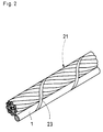
Das in der Fig. 1 beispielhaft dargestellte optische Kabel 1,
das sich insbesondere als an einem Erd- oder Phasenseil einer
Hochspannungsfreileitung befestigtes nicht-selbsttragendes
optisches Luftkabel eignet, hat eine Mehrzahl von optischen
Fasern 3, die gemeinsam von einer einzigen rohrförmigen Hülle
5 umschlossen sind. Dabei können die optischen Fasern 3
gegenüber der rohrförmigen Hülle 5 eine Überlänge von mehr als
10 % aufweisen. Die rohrförmige Hülle 5 ist aus einer aus
einem Kunststoff bestehenden inneren Schicht 7 und einer
unmittelbar darüber liegenden, aus einem Kunststoff
bestehenden äußeren Schicht 9 gebildet, die beide in einem
gemeinsamen Arbeitsschritt extrudiert sind. Beispielsweise im
Bereich zwischen der inneren Schicht 7 und der äußeren Schicht
9 sind in die rohrförmige Hülle 5 zugfeste Elemente 11
eingebettet, die in Längsrichtung des optischen Kabels 1
verlaufen. Zusätzlich sind bei dem dargestellten
Ausführungsbeispiel in der äußeren Schicht 9 der rohrförmigen
Hülle 5 ebenfalls in Längsrichtung des optischen Kabels 1
verlaufende zugfeste Elemente 11' eingebettet. Bei den
zugfesten Elementen 11 und 11' handelt es sich z. B. um
Aramidfasern oder um Aramidfasern enthaltende Elemente. Es
können aber auch beliebige andere hochzugfeste Elemente
verwendet werden. Die rohrförmige Hülle 5 kann zum Schutz der
optischen Fasern 3 vor Feuchtigkeit mit einer geeigneten
thixotropen Masse gefüllt sein.The
Die innere Schicht 7 der rohrförmigen Hülle 5 ist
beispielsweise aus einem einen möglichst hohen amorphen Anteil
und eine entsprechend hohe Glasübergangstemperatur von
zumindest 100°C sowie eine glatte Oberfläche aufweisenden
Kunststoff wie einem teilkristallinen Polyamid ausgebildet.
Für die äußere Schicht 9 der rohrförmigen Hülle 5, die die
äußerste Schicht des optischen Kabels 1 bildet, kommt es bei
der Verlegung des optischen Kabels 1 im Freien darauf an, daß
der verwendete Werkstoff gegenüber UV-Licht und Chemikalien
beständig ist, eine hohe mechanische Festigkeit aufweist und
zudem im Falle der Befestigung des optischen Kabels 1 an einem
Erd- oder Phasenseil eine hohe Kriechstromfestigkeit hat. Aus
diesen Gründen ist die äußere Schicht 9 z. B. aus Polypropylen
ausgebildet. Sie kann aber beispielsweise auch aus einem
geeigneten Polyethylen oder Fluorpolymer ausgebildet sein.The
Die Fig. 2 zeigt ein erfindungsgemäßes optisches Kabel 1, das
an einem Tragseil 21 angeordnet ist. Bei dem Tragseil 21
handelt es sich z. B. um ein Erdseil oder ein Phasenseil einer
Hochspannungsfreileitung. Das optische Kabel 1 ist an dem
Tragseil 21 beispielsweise mittels eines wendelförmig um
Tragseil und optisches Kabel herumgelegten Haltebandes 23
gehalten.Fig. 2 shows an
In der Fig. 3 ist beispielhaft eine Vorrichtung 31 zum
Herstellen eines erfindungsgemäßen optischen Kabels 1
dargestellt. Bei dieser Vorrichtung 31 werden die optischen
Fasern 3 von Vorratsspulen 33 abgezogen und einer
Extrusionseinrichtung 35 zugeführt. Beispielsweise parallel zu
den optischen Fasern 3 gelangen zugfeste Elemente 11 bzw. 11',
die ihrerseits von Vorratsspulen 37 abgezogen werden, in die
Extrusionseinrichtung 35. Die Extrusionseinrichtung 35 weist
beispielsweise zwei Vorratsbehälter für die Kunststoffe der
inneren Schicht und der äußeren Schicht der rohrförmigen Hülle
5 sowie zwei Extruderschnecken auf. In der
Extrusionseinrichtung 35 werden eine innere Schicht und eine
äußere Schicht, die gemeinsam eine zweischichtige rohrförmige
Hülle 5 bilden, in einem Arbeitsschritt zeitgleich mittels
eines gemeinsamen Spritzkopfes gemeinsam um die optischen
Fasern 3 extrudiert. Eine solche gemeinsame Extrusion zweier
Schichten wird auch als Co-Extrusion bezeichnet. Während
dieses Extrusionsprozesses werden die z. B. parallel zu den
optischen Fasern 3 geführten zugfesten Elemente 11 bzw. 11' in
die sich bildende rohrförmige Hülle 5 miteingebracht und in
diese eingebettet.3 is an example of a
Nach der Extrusion ergibt sich ein optisches Kabel 1 mit in
seiner rohrförmigen Hülle 5 eingebetteten zugfesten Elementen
11 bzw. 11', das einen sehr kleinen Außendurchmesser und eine
für viele Anwendungsfälle ausreichende Festigkeit aufweist.After the extrusion, an
Claims (10)
Applications Claiming Priority (2)
| Application Number | Priority Date | Filing Date | Title |
|---|---|---|---|
| DE19717313 | 1997-04-24 | ||
| DE19717313A DE19717313A1 (en) | 1997-04-24 | 1997-04-24 | Optical cable and method for manufacturing an optical cable |
Publications (2)
| Publication Number | Publication Date |
|---|---|
| EP0874262A2 true EP0874262A2 (en) | 1998-10-28 |
| EP0874262A3 EP0874262A3 (en) | 1999-11-17 |
Family
ID=7827616
Family Applications (1)
| Application Number | Title | Priority Date | Filing Date |
|---|---|---|---|
| EP98400795A Withdrawn EP0874262A3 (en) | 1997-04-24 | 1998-04-03 | Optical cable and method of manufacturing an optical cable |
Country Status (6)
| Country | Link |
|---|---|
| US (1) | US6137935A (en) |
| EP (1) | EP0874262A3 (en) |
| BR (1) | BR9801165A (en) |
| CA (1) | CA2232093A1 (en) |
| CO (1) | CO4780032A1 (en) |
| DE (1) | DE19717313A1 (en) |
Cited By (3)
| Publication number | Priority date | Publication date | Assignee | Title |
|---|---|---|---|---|
| EP1302797A3 (en) * | 2001-10-10 | 2004-11-17 | Alcatel | Central strength member with reduced radial stiffness for optical cables |
| EP2105776A2 (en) * | 2008-03-26 | 2009-09-30 | CCS Technology Inc. | Optical cable and method for producing an optical cable |
| CN110631615A (en) * | 2019-08-23 | 2019-12-31 | 华东交通大学 | Method for verifying performance of nano-photonic sensor in contact net metal structure environment |
Families Citing this family (30)
| Publication number | Priority date | Publication date | Assignee | Title |
|---|---|---|---|---|
| DE19605276A1 (en) * | 1996-02-13 | 1997-08-14 | Siemens Ag | Method and device for manufacturing an optical cable |
| WO2003067301A2 (en) * | 2002-02-09 | 2003-08-14 | Ccs Technology, Inc. | Optical fiber cable |
| DE20210216U1 (en) * | 2002-02-09 | 2003-03-20 | Ccs Technology Inc | Optical fiber cable, comprises outer cover and additionally incorporates concentric inner cover which surrounds bundles of optical fibers, takes up tensile loads and functions as support |
| US7206482B2 (en) * | 2004-03-25 | 2007-04-17 | Corning Cable Systems, Llc. | Protective casings for optical fibers |
| US7035513B2 (en) * | 2004-03-25 | 2006-04-25 | Corning Cable Systems Llc | Fiber optic drop cables suitable for outdoor fiber to the subscriber applications |
| WO2007091880A1 (en) * | 2006-02-08 | 2007-08-16 | Draka Comteq B.V. | Optical fiber cable suited for blown installation or pushing installation in microducts of small diameter |
| WO2007091879A1 (en) * | 2006-02-08 | 2007-08-16 | Draka Comteq B.V. | Optical fiber cable suited for blown installation or pushing installation in microducts of small diameter |
| US8885999B2 (en) | 2010-03-19 | 2014-11-11 | Corning Cable Systems Llc | Optical USB cable with controlled fiber positioning |
| CN103620466B (en) | 2011-06-10 | 2017-04-26 | 康宁光缆系统有限责任公司 | Fiber optic cables allowing fiber translation to reduce bend attenuation |
| US8676012B2 (en) | 2012-01-20 | 2014-03-18 | Corning Cable Systems Llc | Fiber optic cable for very-short-distance networks |
| US8620123B2 (en) * | 2012-02-13 | 2013-12-31 | Corning Cable Systems Llc | Visual tracer system for fiber optic cable |
| CN103576270A (en) * | 2012-08-11 | 2014-02-12 | 宁波康润机械科技有限公司 | Optical fiber extrusion device |
| US9170389B2 (en) | 2012-08-28 | 2015-10-27 | Corning Cable Systems Llc | Hybrid fiber optic cable systems |
| US9429731B2 (en) | 2013-08-12 | 2016-08-30 | Corning Optical Communications LLC | Optical fiber cable assembly comprising optical tracer fiber |
| US10379309B2 (en) | 2014-11-18 | 2019-08-13 | Corning Optical Communications LLC | Traceable optical fiber cable and filtered viewing device for enhanced traceability |
| US10228526B2 (en) | 2015-03-31 | 2019-03-12 | Corning Optical Communications LLC | Traceable cable with side-emitting optical fiber and method of forming the same |
| US10101553B2 (en) | 2015-05-20 | 2018-10-16 | Corning Optical Communications LLC | Traceable cable with side-emitting optical fiber and method of forming the same |
| ES2828273T3 (en) * | 2015-06-26 | 2021-05-25 | Prysmian Spa | Procedure for manufacturing a micromodule aerial optical cable |
| WO2017015085A1 (en) | 2015-07-17 | 2017-01-26 | Corning Optical Communications LLC | Systems and methods for tracing cables and cables for such systems and methods |
| WO2017015084A1 (en) | 2015-07-17 | 2017-01-26 | Corning Optical Communications LLC | Systems and methods for traceable cables |
| US10101545B2 (en) | 2015-10-30 | 2018-10-16 | Corning Optical Communications LLC | Traceable cable assembly and connector |
| CN109154701A (en) | 2016-04-08 | 2019-01-04 | 康宁研究与开发公司 | With light structures and for carrying the traceable fiber optical cable assembly from the tracking optical fiber of the received light of light originating device |
| US10107983B2 (en) | 2016-04-29 | 2018-10-23 | Corning Optical Communications LLC | Preferential mode coupling for enhanced traceable patch cord performance |
| US10222560B2 (en) | 2016-12-21 | 2019-03-05 | Corning Research & Development Corporation | Traceable fiber optic cable assembly with fiber guide and tracing optical fibers for carrying light received from a light launch device |
| US10234614B2 (en) | 2017-01-20 | 2019-03-19 | Corning Research & Development Corporation | Light source assemblies and systems and methods with mode homogenization |
| CN107765381B (en) * | 2017-10-17 | 2020-02-18 | 安徽电信器材贸易工业有限责任公司 | Optical cable extrusion device |
| US10539747B2 (en) | 2017-12-05 | 2020-01-21 | Corning Research & Development Corporation | Bend induced light scattering fiber and cable assemblies and method of making |
| US10539758B2 (en) | 2017-12-05 | 2020-01-21 | Corning Research & Development Corporation | Traceable fiber optic cable assembly with indication of polarity |
| WO2023048922A1 (en) * | 2021-09-21 | 2023-03-30 | Corning Research & Development Corporation | Optical fiber cable having tensile strands embedded within cable jacket |
| US20230258902A1 (en) * | 2022-02-16 | 2023-08-17 | Corning Research & Development Corporation | Fanout tube for a furcation of a fiber optic cable and related method |
Citations (7)
| Publication number | Priority date | Publication date | Assignee | Title |
|---|---|---|---|---|
| US4172106A (en) * | 1976-06-24 | 1979-10-23 | Telephone Cables Limited | Optical fibre cables and their manufacture |
| JPS6028611A (en) * | 1983-07-27 | 1985-02-13 | Showa Electric Wire & Cable Co Ltd | Optical fiber core provided with tension wire and optical fiber cable using said core |
| EP0490803A1 (en) * | 1990-12-13 | 1992-06-17 | Cables Pirelli, S.A. | Improvements in dielectric optic fiber cables with anti-inpact protection |
| JPH04186203A (en) * | 1990-11-20 | 1992-07-03 | Mitsubishi Cable Ind Ltd | Optical fiber cable |
| US5360497A (en) * | 1991-12-19 | 1994-11-01 | Siemens Aktiengesellschaft | Method of forming an optical waveguide with a reinforced protective covering |
| FR2725553A1 (en) * | 1994-10-07 | 1996-04-12 | Silec Liaisons Elec | PROCESS FOR PRODUCING A TUBULAR SHEATH COMPRISING FILIFORM CARRIERS, AND TUBULAR SHEATH OBTAINED |
| DE19605276A1 (en) * | 1996-02-13 | 1997-08-14 | Siemens Ag | Method and device for manufacturing an optical cable |
Family Cites Families (4)
| Publication number | Priority date | Publication date | Assignee | Title |
|---|---|---|---|---|
| US5082719A (en) * | 1987-10-30 | 1992-01-21 | At&T Bell Laboratories | Water resistant communications cable |
| US5201020A (en) * | 1990-11-08 | 1993-04-06 | Corning Incorporated | Reinforced protective tube for optical waveguide fibers |
| US5390273A (en) * | 1992-04-02 | 1995-02-14 | Pirelli Cable Corporation | Flame resistant optical fiber cable with optical fibers loosely enclosed in tubes |
| US5748823A (en) * | 1997-01-30 | 1998-05-05 | Siecor Corporation | Single-tube plenum ribbon cable |
-
1997
- 1997-04-24 DE DE19717313A patent/DE19717313A1/en not_active Ceased
-
1998
- 1998-04-03 EP EP98400795A patent/EP0874262A3/en not_active Withdrawn
- 1998-04-15 US US09/060,910 patent/US6137935A/en not_active Expired - Fee Related
- 1998-04-20 CA CA002232093A patent/CA2232093A1/en not_active Abandoned
- 1998-04-21 CO CO98021897A patent/CO4780032A1/en unknown
- 1998-04-22 BR BR9801165-0A patent/BR9801165A/en not_active Application Discontinuation
Patent Citations (7)
| Publication number | Priority date | Publication date | Assignee | Title |
|---|---|---|---|---|
| US4172106A (en) * | 1976-06-24 | 1979-10-23 | Telephone Cables Limited | Optical fibre cables and their manufacture |
| JPS6028611A (en) * | 1983-07-27 | 1985-02-13 | Showa Electric Wire & Cable Co Ltd | Optical fiber core provided with tension wire and optical fiber cable using said core |
| JPH04186203A (en) * | 1990-11-20 | 1992-07-03 | Mitsubishi Cable Ind Ltd | Optical fiber cable |
| EP0490803A1 (en) * | 1990-12-13 | 1992-06-17 | Cables Pirelli, S.A. | Improvements in dielectric optic fiber cables with anti-inpact protection |
| US5360497A (en) * | 1991-12-19 | 1994-11-01 | Siemens Aktiengesellschaft | Method of forming an optical waveguide with a reinforced protective covering |
| FR2725553A1 (en) * | 1994-10-07 | 1996-04-12 | Silec Liaisons Elec | PROCESS FOR PRODUCING A TUBULAR SHEATH COMPRISING FILIFORM CARRIERS, AND TUBULAR SHEATH OBTAINED |
| DE19605276A1 (en) * | 1996-02-13 | 1997-08-14 | Siemens Ag | Method and device for manufacturing an optical cable |
Non-Patent Citations (2)
| Title |
|---|
| PATENT ABSTRACTS OF JAPAN vol. 009, no. 151 (P-367), 26. Juni 1985 (1985-06-26) & JP 60 028611 A (SHOWA DENSEN DENRAN KK), 13. Februar 1985 (1985-02-13) * |
| PATENT ABSTRACTS OF JAPAN vol. 016, no. 511 (P-1441), 21. Oktober 1992 (1992-10-21) & JP 04 186203 A (MITSUBISHI CABLE IND LTD), 3. Juli 1992 (1992-07-03) * |
Cited By (5)
| Publication number | Priority date | Publication date | Assignee | Title |
|---|---|---|---|---|
| EP1302797A3 (en) * | 2001-10-10 | 2004-11-17 | Alcatel | Central strength member with reduced radial stiffness for optical cables |
| EP2105776A2 (en) * | 2008-03-26 | 2009-09-30 | CCS Technology Inc. | Optical cable and method for producing an optical cable |
| EP2105776A3 (en) * | 2008-03-26 | 2014-01-01 | CCS Technology Inc. | Optical cable and method for producing an optical cable |
| CN110631615A (en) * | 2019-08-23 | 2019-12-31 | 华东交通大学 | Method for verifying performance of nano-photonic sensor in contact net metal structure environment |
| CN110631615B (en) * | 2019-08-23 | 2021-08-17 | 华东交通大学 | Method for verifying performance of nano-photonic sensor in contact net metal structure environment |
Also Published As
| Publication number | Publication date |
|---|---|
| CA2232093A1 (en) | 1998-10-24 |
| US6137935A (en) | 2000-10-24 |
| DE19717313A1 (en) | 1998-11-05 |
| CO4780032A1 (en) | 1999-05-26 |
| EP0874262A3 (en) | 1999-11-17 |
| BR9801165A (en) | 1999-10-13 |
Similar Documents
| Publication | Publication Date | Title |
|---|---|---|
| EP0874262A2 (en) | Optical cable and method of manufacturing an optical cable | |
| EP0126509B1 (en) | Optical cable element or cable, and method of making it | |
| DE2820510C2 (en) | Electric overhead conductor | |
| DE10028562A1 (en) | Air cable containing optical transmission elements and method of manufacturing an air cable | |
| DE3118172C2 (en) | ||
| DE2641166A1 (en) | COVERED FIBER OPTIC | |
| DE4020800A1 (en) | METHOD FOR PRODUCING A STRENGTHENED PLASTIC COVER | |
| DE3232108C2 (en) | ||
| EP0072594B1 (en) | Optical telecommunication cable | |
| DE3023669C2 (en) | Self-supporting optical communication cable | |
| DE60211817T2 (en) | Optical hollow conductor cable with fiber ribbon | |
| DE2817045A1 (en) | OPTICAL CABLE | |
| DE19740726A1 (en) | Overhead fiber optic cable | |
| DE2701650C2 (en) | Core for an optical cable or an optical cable element | |
| EP1970487B1 (en) | Funicular support rope | |
| DE3940938A1 (en) | High tensile strength low wt. cable - has double-sheathed optical fibre, non-metallic reinforcing strands, spaces filled with polymer and thin outermost thermoplastic sleeve | |
| DE19508888C2 (en) | Flexible electrical power line | |
| EP0261675A2 (en) | Optical cable | |
| DE3606589C2 (en) | ||
| EP0677759A1 (en) | Optical cable with stain and compression resistant bundels | |
| DE4015568A1 (en) | FO AIR CABLE FOR LARGE CLAMPING LENGTHS | |
| DE3513592C2 (en) | ||
| DE19705920C2 (en) | Process for the production of coated glass bundles | |
| DE3319370A1 (en) | Optical aerial cable having a tubular support element | |
| EP0156097B1 (en) | Cable |
Legal Events
| Date | Code | Title | Description |
|---|---|---|---|
| PUAI | Public reference made under article 153(3) epc to a published international application that has entered the european phase |
Free format text: ORIGINAL CODE: 0009012 |
|
| AK | Designated contracting states |
Kind code of ref document: A2 Designated state(s): DE ES FR GB IT SE |
|
| AX | Request for extension of the european patent |
Free format text: AL;LT;LV;MK;RO;SI |
|
| RAP1 | Party data changed (applicant data changed or rights of an application transferred) |
Owner name: ALCATEL |
|
| PUAL | Search report despatched |
Free format text: ORIGINAL CODE: 0009013 |
|
| AK | Designated contracting states |
Kind code of ref document: A3 Designated state(s): AT BE CH CY DE DK ES FI FR GB GR IE IT LI LU MC NL PT SE |
|
| AX | Request for extension of the european patent |
Free format text: AL;LT;LV;MK;RO;SI |
|
| 17P | Request for examination filed |
Effective date: 19991103 |
|
| 17Q | First examination report despatched |
Effective date: 20000228 |
|
| AKX | Designation fees paid | ||
| REG | Reference to a national code |
Ref country code: DE Ref legal event code: 8566 |
|
| RBV | Designated contracting states (corrected) |
Designated state(s): DE ES FR GB IT SE |
|
| STAA | Information on the status of an ep patent application or granted ep patent |
Free format text: STATUS: THE APPLICATION IS DEEMED TO BE WITHDRAWN |
|
| 18D | Application deemed to be withdrawn |
Effective date: 20000711 |