EP1162371B1 - Verdichter und verfahren zur schmierung des verdichters - Google Patents
Verdichter und verfahren zur schmierung des verdichters Download PDFInfo
- Publication number
- EP1162371B1 EP1162371B1 EP00980044A EP00980044A EP1162371B1 EP 1162371 B1 EP1162371 B1 EP 1162371B1 EP 00980044 A EP00980044 A EP 00980044A EP 00980044 A EP00980044 A EP 00980044A EP 1162371 B1 EP1162371 B1 EP 1162371B1
- Authority
- EP
- European Patent Office
- Prior art keywords
- piston
- outlet
- oil supply
- supply hole
- channel
- Prior art date
- Legal status (The legal status is an assumption and is not a legal conclusion. Google has not performed a legal analysis and makes no representation as to the accuracy of the status listed.)
- Expired - Lifetime
Links
- 238000000034 method Methods 0.000 title description 7
- 230000001050 lubricating effect Effects 0.000 title description 3
- 239000003921 oil Substances 0.000 claims description 70
- 239000000126 substance Substances 0.000 claims description 37
- 239000010687 lubricating oil Substances 0.000 claims description 34
- 239000003507 refrigerant Substances 0.000 claims description 31
- 239000010802 sludge Substances 0.000 claims description 21
- 238000005461 lubrication Methods 0.000 claims description 17
- CURLTUGMZLYLDI-UHFFFAOYSA-N Carbon dioxide Chemical group O=C=O CURLTUGMZLYLDI-UHFFFAOYSA-N 0.000 claims description 9
- 229910002092 carbon dioxide Inorganic materials 0.000 claims description 6
- 239000001569 carbon dioxide Substances 0.000 claims description 6
- 238000000926 separation method Methods 0.000 description 11
- 230000015556 catabolic process Effects 0.000 description 9
- 238000006731 degradation reaction Methods 0.000 description 9
- 230000008569 process Effects 0.000 description 5
- 239000000314 lubricant Substances 0.000 description 4
- 238000010408 sweeping Methods 0.000 description 4
- 230000009471 action Effects 0.000 description 3
- 238000001816 cooling Methods 0.000 description 3
- 238000010586 diagram Methods 0.000 description 3
- 230000007246 mechanism Effects 0.000 description 3
- 238000004519 manufacturing process Methods 0.000 description 2
- 238000004378 air conditioning Methods 0.000 description 1
- 230000006835 compression Effects 0.000 description 1
- 238000007906 compression Methods 0.000 description 1
- 238000007599 discharging Methods 0.000 description 1
- 230000000694 effects Effects 0.000 description 1
- 230000005484 gravity Effects 0.000 description 1
- 238000012986 modification Methods 0.000 description 1
- 230000004048 modification Effects 0.000 description 1
Images


Classifications
-
- F—MECHANICAL ENGINEERING; LIGHTING; HEATING; WEAPONS; BLASTING
- F04—POSITIVE - DISPLACEMENT MACHINES FOR LIQUIDS; PUMPS FOR LIQUIDS OR ELASTIC FLUIDS
- F04B—POSITIVE-DISPLACEMENT MACHINES FOR LIQUIDS; PUMPS
- F04B27/00—Multi-cylinder pumps specially adapted for elastic fluids and characterised by number or arrangement of cylinders
- F04B27/08—Multi-cylinder pumps specially adapted for elastic fluids and characterised by number or arrangement of cylinders having cylinders coaxial with, or parallel or inclined to, main shaft axis
- F04B27/10—Multi-cylinder pumps specially adapted for elastic fluids and characterised by number or arrangement of cylinders having cylinders coaxial with, or parallel or inclined to, main shaft axis having stationary cylinders
- F04B27/1036—Component parts, details, e.g. sealings, lubrication
- F04B27/109—Lubrication
Definitions
- the present invention relates to a compressor that is ideal for a vehicle air-conditioning system, and more specifically to a lubrication technique that guides lubricating oil to lubrication target areas, such as the bearing of a drive shaft and the sliding surface between a piston and a cylinder bore.
- a compressor that guides lubricating oil to the bearing of a drive shaft is disclosed, for example, in Japanese Laid-Open Patent Publication No. 7-27047.
- the compressor described in this publication is a swash plate compressor, in which a refrigerant gas that is discharged into a discharge chamber is guided to an oil separator provided in a cylinder block, thereby separating the lubricating oil from the refrigerant gas, and then the separated lubricating oil is guided to the bearing of a drive shaft via an oil supply hole provided in the cylinder block for lubrication.
- the compressor configured as described above guides the oil separated from the discharged refrigerant to the bearing for lubrication, using the pressure difference between the oil separation chamber, which is at a higher pressure, and a drive chamber, which is at a lower pressure, and then returns the oil to the drive chamber. Consequently, if the diameter of the lubricating oil supply hole formed in the cylinder block is too large, leakage of the discharged refrigerant causes a degradation in performance, and leakage of a large amount of high-temperature lubricating oil heats the refrigerant that has been drawn in, thereby causing performance degradation. On the other hand, if the oil supply hole is too small, foreign substances, such as sludge (oil sludge), tend to clog the oil supply hole, and manufacturing such a small hole is also difficult.
- sludge oil sludge
- the operation pressure difference (the difference between a discharge pressure and a suction pressure) is large (5 MPa or greater) and therefore, said conflicting requirements become more difficult to satisfy.
- DE-A-199 07 492 proposes a CO 2 compressor according to the preamble of claim 1.
- the compressor comprises a fixed member remaining stationary, a movable member slidable relatively with the fixed member, and an intermittent oil supply mechanism in which a part of the oil path opened to the surface of the fixed member is opened or closed by the movable member thereby to allow the lubricating oil to be passed intermittently under pressure to the parts requiring lubrication.
- the intermittent oil supply mechanism supplies the oil to the parts requiring lubrication by adjusting the lubricant flow rate without using any pressure reducing parts for reducing the size of the lubricant flow path.
- the lubricant is supplied to a radial bearing of drive shaft via a slight clearance between the bearing retainer and the cylindrical hole accommodating the radial bearing.
- the intermittent oil supply mechanism shortens the substantial lubrication time and limits the amount of oil supplied, there is still the risk that the clearance between the bearing retainer and the cylindrical hole restricts the flow of the oil to such an extent that the oil path is clogged.
- the present invention has been developed in view of said existing problems, and its objectives are to prevent the clogging of the oil supply hole by foreign substances, such as sludge, and to avoid performance degradation caused by leakage of the discharged refrigerant, especially when the compressor uses CO 2 as the refrigerant.
- a compressor as set forth in claim 1.
- a flow rate restriction channel communicated to the outlet of the oil supply hole restricts the flow of the lubricating oil, thereby reducing the flow rate.
- the channel is defined between a cylindrical hole and a member that rotates or reciprocates inside this cylindrical hole. Consequently, even when foreign substances, such as sludge, flow from the oil supply hole to the channel, the foreign substances are swept out from the outlet of the oil supply hole due to the relative movement of the rotating or reciprocating member.
- the channel is defined by a gap between the cylindrical hole and the member that rotates or reciprocates inside the cylindrical hole, the channel can be formed more easily than a case in which a channel is formed by boring.
- the lubricating oil to be sent to the lubrication target area should preferably be lubricating oil that has been separated from the discharged refrigerant, and should preferably be guided based on the pressure difference between the discharged side and the suction side.
- Such a configuration is especially effective when applied to a compressor that uses carbon dioxide as the refrigerant.
- the foreign substance sweep-out groove on the external surface of the rotating member and the foreign substance sweep-out groove intermittently communicates with the outlet of the oil supply hole.
- the groove faces the outlet of the oil supply hole, foreign substances, such as sludge, that flow in via the oil supply hole can be captured. Therefore, the sweeping of foreign substances, such as sludge, can be more actively performed, making it possible to more effectively prevent the clogging of the oil supply hole.
- the flow rate of the lubricating oil flowing into the sliding surface via the oil supply hole is controlled by the channel defined between the piston and the cylinder bore.
- foreign substances such as sludge
- This action prevents the clogging of the oil supply hole and suppresses leakage of the discharged refrigerant, thereby avoiding performance degradation.
- a stepped surface is provided at the boundary between the gap comprising the channel and the side clearance between the external surface of the piston and the internal surface of the cylinder bore.
- This stepped surface should preferably be provided in a position that crosses the outlet of the oil supply hole when the piston moves toward the bottom dead center.
- foreign substances such as sludge
- flowing in via the oil supply hole can be swept out from the outlet of the oil supply hole by the stepped surface.
- the channel defined between the piston and the cylinder bore should preferably comprise a groove that is provided on the external surface of the piston and that extends in the axial direction.
- the channel can increase the flow-restriction effect, thereby better restricting leakage of the discharged refrigerant.
- the foreign substances swept out from the oil supply hole should preferably be discharged into a drive chamber having a relatively large space.
- FIG 1 is a cross-sectional diagram showing a compressor related to the present embodiment.
- FIG 2 is a magnified cross-sectional diagram showing the rotating member and the oil supply hole.
- FIG 3 is a magnified view of Area A in FIG 1.
- FIG 4 is a cross-sectional diagram showing a compressor that relates to another embodiment.
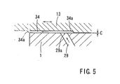
- FIG 5 is a magnified view of Area B in FIG 4.
- FIG 1 the embodiments of the present invention are applied to a swash plate compressor.
- a front housing 2 is joined to the front end of a cylinder block 1, which comprises part of the external frame of the compressor; a rear housing 5, in which an suction chamber 3 and a discharge chamber 4 are defined, is joined to the rear end via a valve plate 6.
- a drive shaft 8 that will be connected to a power source is inserted through the drive chamber 7 formed inside the front housing 2, and the drive shaft 8 is rotatably supported by the cylinder block 1 and the front housing 2 via radial bearings 9 and 10, respectively.
- a swash plate 11 is disposed inside the drive chamber 7 and is secured to the drive shaft 8.
- the cylinder block 1 has multiple cylinder bores 12 that are bored at predetermined intervals in the circumferential direction, and a piston 13 is slidably fitted inside each of the cylinder bores 12. The front end of the piston 13 extends into the drive chamber 7, and at the same time, is engaged with the swash plate 11 via a shoe 14.
- FIG 1 shows the piston 13 at the top dead center (discharge completion position) while bottom portion shows piston 13 at the bottom dead center (suction completion position).
- the urging force of the disc spring 17 is then supported by a thrust bearing 18, which is positioned between the swash plate 11 and the front housing 2.
- a chamber 19 is provided in the center of the cylinder block 1, which faces the valve plate 6, and the chamber 19 communicates with the discharge chamber 4 via a first discharge channel 20 in approximately the mid-section in the vertical direction, and communicates with a cooling circuit, which is an external circuit, via a second discharge channel 21 on the top side.
- the first discharge channel 20 is bored through a fixture 22 used for securing the discharge valve 15 to the valve plate 6.
- a centrifugal separation oil separator 23 which separates the lubricating oil from the high-pressure refrigerant gas sent out to the cooling circuit via the chamber 19, is disposed inside the chamber 19.
- the oil separator 23 consists of a base 25, which has a separation chamber 24 that is in the shape of a circular hole with a bottom, and a flanged gas-guiding tube 26 installed in the base 25 so as to concentrically hang down from the upper opening edge of the separation chamber 24; a throughhole 27, which permits the separation chamber 24 to communicate with the first discharge channel 20, is provided on the side wall of the base 25.
- the throughhole 27 opens almost tangentially toward the inside of the separation chamber 24.
- the lubricating oil that is force-fed and guided into the separation chamber 24 together with the refrigerant gas by circling around the gas-guiding tube 26 from the first discharge channel 20 via the throughhole 27 collides with the perimeter wall of the separation chamber 24 due to centrifugal force, at the same time, is separated from the refrigerant and flows down, and collects on the bottom of the chamber 19 by passing through a throughhole 28 provided on the bottom wall of the separation chamber 24.
- the discharged refrigerant from which the lubricating oil has been separated is sent to the cooling circuit from the gas-guiding tube 26 via the second discharge channel 21.
- an oil supply hole 29 for guiding the lubricating oil collected inside the chamber 19 to the radial bearing 10 of the drive shaft 8 is defined in the cylinder block 1.
- the inlet of the oil supply hole 29 opens to the bottom of the chamber 19 and its outlet 29a (see FIGS. 2 and 3) opens to the part of the internal surface of a circular hole 31 that faces the external surface of a rotating member 30.
- the rotating member 30 is positioned adjacent to the radial bearing 10 and is fitted by the width across flats on the rear end of the drive shaft 8 (see FIG 2), and rotates together with the drive shaft 8.
- the rotating member 30 is fitted into the circular hole 31 formed in the cylinder block 1, with a gap, and one end of this gap faces the side surface of the radial bearing 10. That is, as shown in the magnified view in FIG 3, the gap defines a channel 32 for controlling (reducing) the flow rate of the lubricating oil, and the oil supply hole 29 communicates with the radial bearing 10 of the drive shaft 8 via the channel 32.
- the channel 32 is defined such that the area determined by the perimeter of the outlet 29a and the height of the channel 32 (the gap between the rotating member 30 and the circular hole 31) is significantly smaller compared to the area of the outlet 29a of the oil supply hole 29. In this way, the channel 32 functions as a restricting channel.
- a single groove 33 which extends in the axial direction for actively sweeping out foreign substances, such as sludge, is defined on the external surface of the rotating member 30.
- One end of the groove 33 in the axial direction opens to the bottom of the circular hole 31, and the other end which faces the radial bearing 10 is closed.
- the compressor related to the embodiment of the present invention is configured as described above. Therefore, when the piston 13, which is coupled to the swash plate 11 rotating with the drive shaft 8, reciprocates inside the cylinder bore 12, the compression work begins and the compressed refrigerant gas pushes open the discharge valve 15 and is discharged into the discharge chamber 4, and is then guided from the first discharge channel 20 into the chamber 19. Then, the lubricating oil within the refrigerant gas, which is introduced into the chamber 19 while circulating, is separated from the refrigerant gas by a centrifugal force inside the separation chamber 24, flows down the wall of the separation chamber 24 due to gravity, and is collected via the throughhole 28 on the bottom of the chamber 19.
- the lubricating oil collected inside the chamber 19 is force-fed from the oil supply hole 29 via the channel 32 to the radial bearing 10 of the drive shaft 8, which has a lower pressure than the pressure (discharge pressure) inside the chamber 19, and after lubricating the radial bearing 10, is released into the drive chamber 7.
- the flow rate of the lubricating oil that flows out from the outlet 29a of the oil supply hole 29 is restricted by the channel 32 defined between the external surface of the rotating member 30 and the internal surface of the circular hole 31. That is, the flow rate of the lubricating oil that is fed via the oil supply hole 29 is restricted using the cross-sectional area of the channel (gap) 32 as the minimum throttle when flowing to the radial bearing 10.
- This design can suppress leakage of the discharged refrigerant inside the chamber 19 to the drive chamber 7 via the oil supply hole 29 for the lubricating oil.
- the groove 33 which extends in the axial direction, is formed on the external surface of the rotating member 30, and therefore, by having the groove 33 intermittently face the outlet 29a of the oil supply hole 29, foreign substances can be actively captured and swept out. Clogging of the oil supply hole 29 is thus prevented, and excellent lubricating effects can be obtained by eliminating a lubricating oil shortage that will be caused by a clogged hole. Note that as the volume of the foreign substances captured in the groove 33 increases, the foreign substances are gradually sent out to and are collected on the bottom of the circular hole 31 from the open end of the groove 33. During this process, foreign substances are prevented from flowing out to the radial bearing 10 because the other end of the groove 33 is blocked.
- the channel 32 that communicates with the outlet 29a of the oil supply hole 29 restrict the flow rate, the hole diameter of the oil supply hole 29 can be set large, making the boring process easy. Additionally, because the channel 32 includes the gap between the rotating member 30 and the circular hole 31, manufacturing is easier than a case in which the channel is formed by boring.
- the cylinder bore 12 and the piston 13 that reciprocates inside the cylinder bore 12 are the lubrication target areas.
- the inlet of the oil supply hole 29 provided in the cylinder block 1 opens to the bottom surface of the oil separator 23 and the outlet 29a thereof opens to the internal surface of the cylinder bore 12.
- a groove provides a gap of a predetermined size from the internal surface of the cylinder bore 12 and is defined on the external surface of the piston 13 in a location that faces the outlet 29a of the oil supply hole 29. That is, this groove defines a channel 34 for restricting the flow rate of the lubricating oil, and the channel 34 is defined such that the area defined by the perimeter of the outlet 29a and the height of the channel 34 (the distance from the internal surface of the cylinder bore to the bottom of the gap) is significantly smaller compared to the area of the outlet 29a of the oil supply hole 29. In this way, the channel 34 functions as a restricting channel.
- the piston 13 is fitted into the cylinder bore 12 with a minimum gap C (hereinafter referred to as "the side clearance") necessary for proper reciprocating movements. Because the gap of the channel 34 is larger than side clearance C, a stepped surface 34a is provided at the boundary with side clearance C.
- the stepped surface 34a is designed to actively sweep out foreign substances, such as sludge, from the outlet 29a of the oil supply hole 29, and is provided in a position that crosses at least the outlet 29a of the oil supply hole 29 when the piston 13 is positioned at the bottom dead center during the suction process in which the piston 13 is moved toward the drive chamber 7, and in the present embodiment, in the position outside the cylinder bore 12 (the position indicated by an imaginary line in FIG 5), which is considered optimal for sweeping out foreign substances.
- the stepped surface 34a is provided in certain locations, and therefore, during the suction process of the piston 13, the stepped surface 34a can sweep out any foreign substances, such as sludge, that might be present at the outlet 29a of the oil supply hole 29 and actively discharge the foreign substances to the drive chamber 7, which has a large space.
- the flow rate of the lubricating oil that flows in from the oil supply hole 29 is restricted by the channel 34 having a smaller cross-sectional area than the oil supply hole 29, and such flow rate restriction suppresses leakage of discharged refrigerant and the lubricating oil is actively supplied to the sliding surface between the piston 13 and the cylinder bore 12.
- the single sweep-out groove 33 is provided on the external surface of the rotating member 30.
- this groove may be increased in number or eliminated.
- the rotating member 30 may also be integrally formed with the drive shaft 8.
- the channel 34 is defined on the external surface of the piston 13.
- a gap may be provided around the entire perimeter of the piston, i.e., the channel 34 may be formed between the piston 13 and the cylinder bore 12 by forming a smaller-diameter area.
- the stepped surface 34a formed on the piston 13 is designed to actively sweep out foreign substances, such as sludge, and is provided in the position that crosses the outlet 29a of the oil supply hole 29 during the reciprocating movements of the piston 13, and more preferably in the position outside the cylinder bore 12.
- the stepped surface 34a is not be restricted to said position, and it may be provided in a position that does not cross the outlet 29a when the piston 13 moves to the bottom dead center. Note that such stepped surface 34a will have a function of restricting foreign substances, such as sludge, from discharging toward the head of the piston 13.
- the present invention can of course be applied to other compressors in addition to the swash plate type compressors shown in the figures, and the oil separator 23 also is not limited to the centrifugal type shown in the figures, and other types may be used without any problems.
- the present invention can, in a compressor, prevent clogging of the lubricant oil supply hole by foreign substances, such as sludge, and can avoid performance degradation due to leakage of the discharged refrigerant.
Landscapes
- Engineering & Computer Science (AREA)
- Mechanical Engineering (AREA)
- General Engineering & Computer Science (AREA)
- Compressor (AREA)
- Compressors, Vaccum Pumps And Other Relevant Systems (AREA)
Claims (10)
- Kompressor mit einer zu schmierenden Schmierzielzone (10; 12, 13), einer Ölzuführöffnung (29) zum Leiten des Schmieröls zu der Schmierzielzone und einem mit einem Auslass (29a) der Ölzuführöffnung (29) in Verbindung stehenden Strömungsbegrenzungskanal (32; 34) zur Begrenzung der Strömung des Schmieröls,
dadurch gekennzeichnet, dass
der Strömungsbegrenzungskanal (32; 34) einen zwischen einer Zylinderbohrung (31; 12) und einem Teil (30; 13), das sich dreht oder in der Zylinderbohrung hin- und herbewegt, ausgebildeten Spalt umfasst und so ausgebildet ist, dass die vom Umfang des Auslasses (29a) und der Höhe des Kanals (32; 34) gebildete Zone verglichen mit der Zone des Auslasses (29a) kleiner ist, und Fremdkörper, wie z.B. Schlamm, von dem Auslass (29a) infolge der Bewegung des sich drehenden oder hin- und herbewegenden Teils (30; 13) herausbewegt werden. - Kompressor nach Anspruch 1, der als Kolbenkompressor ausgebildet ist, wobei das Schmieröl von einem Kühlmittel abgetrennt wird und der Schmierzielzone (10; 12, 13) auf der Grundlage einer Druckdifferenz zwischen einer Auslassseite und einer Ansaugseite des Kolbenkompressors zugeleitet wird.
- Kompressor nach Anspruch 2, wobei das Kühlmittel Kohlendioxid ist.
- Kompressor nach einem der Ansprüche 1 bis 3, wobei der Kanal einen zwischen einer Außenfläche des an einer Antriebswelle (8) angeordneten Drehteils (30) und einer Innenfläche der Zylinderbohrung (31), die das Drehteil (30) drehbar lagert, ausgebildeten Spalt (32) umfasst.
- Kompressor nach Anspruch 4, wobei die Außenfläche des Drehteils (30) eine Nut (33) zum Herausbewegen von Fremdkörpern aufweist, die intermittierend mit dem Auslass (29a) der Ölzuführöffnung (29) in Verbindung steht.
- Kompressor nach einem der Ansprüche 1 bis 3, wobei der Kanal einen zwischen einer Außenfläche eines Kolbens (13), der sich linear hin- und herbewegt, und einer Innenfläche der Zylinderbohrung (12), die den Kolben (13) gleitbar lagert, gebildeten Spalt (34) umfasst, und der Spalt (34) größer als ein zwischen der Außenfläche des Kolbens (13) und der Innenfläche der Zylinderbohrung (12) an einer Kopfseite des Kolbens (13) gebildetes Seitenspiel (C) ist, so dass ein Absatz (34a) an der Grenze zu dem Seitenspiel (C) ausgebildet wird.
- Kompressor nach Anspruch 6, wobei der Absatz (34a) an einer Stelle vorgesehen ist, die den Auslass (29a) der Ölzuführöffnung (29) kreuzt, wenn sich der Kolben (13) in Richtung zu seinem unteren Totpunkt bewegt.
- Kompressor nach Anspruch 6 oder 7, wobei der Absatz (34a) sich von der Zylinderbohrung (12) nach außen erstreckt, wenn der Kolben (13) am unteren Totpunkt angeordnet ist.
- Kompressor nach einem der Ansprüche 6 bis 8, wobei der Spalt mittels einer Nut gebildet wird, die auf einer Außenfläche des Kolbens (13) vorgesehen ist und sich in axialer Richtung erstreckt.
- Kompressor nach Anspruch 9, wobei die von dem Auslass (29a) herausbewegten Fremdkörper, wie z.B. Schlamm, in eine Antriebskammer (7), die einem Basisende des Kolbens (13) zugewandt ist, ausgegeben werden.
Applications Claiming Priority (3)
| Application Number | Priority Date | Filing Date | Title |
|---|---|---|---|
| JP35485199 | 1999-12-14 | ||
| JP35485199A JP4026290B2 (ja) | 1999-12-14 | 1999-12-14 | 圧縮機 |
| PCT/JP2000/008754 WO2001044660A1 (fr) | 1999-12-14 | 2000-12-11 | Compresseur et son procede de graissage |
Publications (3)
| Publication Number | Publication Date |
|---|---|
| EP1162371A1 EP1162371A1 (de) | 2001-12-12 |
| EP1162371A4 EP1162371A4 (de) | 2002-11-04 |
| EP1162371B1 true EP1162371B1 (de) | 2005-11-16 |
Family
ID=18440346
Family Applications (1)
| Application Number | Title | Priority Date | Filing Date |
|---|---|---|---|
| EP00980044A Expired - Lifetime EP1162371B1 (de) | 1999-12-14 | 2000-12-11 | Verdichter und verfahren zur schmierung des verdichters |
Country Status (5)
| Country | Link |
|---|---|
| US (1) | US6582202B2 (de) |
| EP (1) | EP1162371B1 (de) |
| JP (1) | JP4026290B2 (de) |
| DE (1) | DE60024068T2 (de) |
| WO (1) | WO2001044660A1 (de) |
Families Citing this family (9)
| Publication number | Priority date | Publication date | Assignee | Title |
|---|---|---|---|---|
| DE10214045B4 (de) * | 2002-03-28 | 2015-07-16 | Volkswagen Ag | R 744-Kompressor für eine Fahrzeug-Klimaanlage |
| EP1490598B1 (de) * | 2002-03-29 | 2006-11-29 | DeVilbiss Air Power Company | Kopfdruckentlastungsanordnung |
| EP1508695B1 (de) * | 2002-05-14 | 2008-05-21 | Zexel Valeo Climate Control Corporation | Hubkolbenkompressor |
| DE10300919A1 (de) | 2003-01-13 | 2004-07-22 | Kunststoff-Technik Scherer & Trier Gmbh & Co Kg | Mehrlagiges Dekorband und Verfahren zur Herstellung eines mehrlagigen Dekorbandes |
| US7060122B2 (en) * | 2003-10-06 | 2006-06-13 | Visteon Global Technologies, Inc. | Oil separator for a compressor |
| US7178450B1 (en) | 2005-10-06 | 2007-02-20 | Delphi Technologies, Inc. | Sealing system for a compressor |
| WO2008072810A1 (en) * | 2006-12-14 | 2008-06-19 | Doowon Technical College | Oil separator for reciprocating compressor having insulation function |
| US20100101269A1 (en) * | 2008-10-24 | 2010-04-29 | Theodore Jr Michael | Compressor with improved oil separation |
| US20140308139A1 (en) * | 2013-04-10 | 2014-10-16 | Medhat Kamel Bahr Khalil | Double swash plate pump with adjustable valve ring concept |
Family Cites Families (14)
| Publication number | Priority date | Publication date | Assignee | Title |
|---|---|---|---|---|
| US2963113A (en) * | 1957-10-03 | 1960-12-06 | Carrier Corp | Compressor lubrication system |
| US3945765A (en) | 1974-04-15 | 1976-03-23 | Sankyo Electric Co., Ltd. | Refrigerant compressor |
| JPS58206826A (ja) * | 1982-05-28 | 1983-12-02 | Aisin Seiki Co Ltd | タ−ボチヤ−ジヤ |
| JPS6320864A (ja) | 1986-07-14 | 1988-01-28 | Nec Corp | 半動体装置 |
| JP2718666B2 (ja) * | 1986-07-21 | 1998-02-25 | 株式会社日立製作所 | スクロール流体機械の給油装置 |
| US5301771A (en) * | 1991-08-22 | 1994-04-12 | Carrier Corporation | Oil channeling in a centrifugal compressor transmission |
| JPH0727047A (ja) | 1993-07-05 | 1995-01-27 | Toyota Autom Loom Works Ltd | 往復動型圧縮機 |
| JPH07332239A (ja) | 1994-06-03 | 1995-12-22 | Toyota Autom Loom Works Ltd | 往復動型圧縮機 |
| JPH08284835A (ja) * | 1995-04-18 | 1996-10-29 | Toyota Autom Loom Works Ltd | 片頭ピストン圧縮機 |
| JPH10141227A (ja) | 1996-11-13 | 1998-05-26 | Matsushita Refrig Co Ltd | 圧縮機 |
| JP3666170B2 (ja) * | 1997-03-04 | 2005-06-29 | 株式会社デンソー | 斜板型圧縮機 |
| JPH11182431A (ja) | 1997-12-24 | 1999-07-06 | Toyota Autom Loom Works Ltd | 圧縮機 |
| JP3851971B2 (ja) * | 1998-02-24 | 2006-11-29 | 株式会社デンソー | Co2用圧縮機 |
| JP4008098B2 (ja) * | 1998-04-10 | 2007-11-14 | イーグル工業株式会社 | 冷凍機コンプレッサの軸封構造 |
-
1999
- 1999-12-14 JP JP35485199A patent/JP4026290B2/ja not_active Expired - Fee Related
-
2000
- 2000-12-11 WO PCT/JP2000/008754 patent/WO2001044660A1/ja not_active Ceased
- 2000-12-11 EP EP00980044A patent/EP1162371B1/de not_active Expired - Lifetime
- 2000-12-11 US US09/913,456 patent/US6582202B2/en not_active Expired - Fee Related
- 2000-12-11 DE DE60024068T patent/DE60024068T2/de not_active Expired - Lifetime
Also Published As
| Publication number | Publication date |
|---|---|
| US20020159894A1 (en) | 2002-10-31 |
| JP4026290B2 (ja) | 2007-12-26 |
| US6582202B2 (en) | 2003-06-24 |
| EP1162371A1 (de) | 2001-12-12 |
| DE60024068D1 (de) | 2005-12-22 |
| WO2001044660A1 (fr) | 2001-06-21 |
| DE60024068T2 (de) | 2006-07-27 |
| EP1162371A4 (de) | 2002-11-04 |
| JP2001165048A (ja) | 2001-06-19 |
Similar Documents
| Publication | Publication Date | Title |
|---|---|---|
| KR100209480B1 (ko) | 가변용량 압축기 | |
| EP1160449B1 (de) | Verdichter und verfahren zur schmierung des kompressors | |
| US8241012B2 (en) | Structure for mounting a filter in a compressor | |
| EP1906015A1 (de) | Verdichter | |
| EP0738832B1 (de) | Schmiervorrichtung für Kolbenverdichter | |
| EP0943802A2 (de) | Schrägscheibenverdichter mit variabler Förderleistung mit Ölabscheider | |
| EP1162371B1 (de) | Verdichter und verfahren zur schmierung des verdichters | |
| US6568917B2 (en) | Reciprocating compressor and method of lubricating the reciprocating compressor | |
| KR20040071579A (ko) | 압축기에 있어서의 윤활구조 | |
| EP1717445A1 (de) | Verdichter | |
| EP1508695B1 (de) | Hubkolbenkompressor | |
| US20090074592A1 (en) | Compressor and method for operating the same | |
| EP1712791A2 (de) | Taumelscheibenverdichter | |
| US5890878A (en) | Valve structure in compressor | |
| KR100818574B1 (ko) | 압축기에서의 오일 회수 구조 | |
| KR101386381B1 (ko) | 피스톤형 압축기 | |
| JPH0361680A (ja) | オイルセパレータ | |
| JP2007127118A (ja) | ピストン型圧縮機 | |
| JP2001003867A (ja) | 横型圧縮機 | |
| KR100799767B1 (ko) | 왕복동식 압축기의 윤활 구조 | |
| JP7164724B2 (ja) | 圧縮機 | |
| JP2005226467A (ja) | 気体圧縮機 | |
| JP2017172386A (ja) | 圧縮機 |
Legal Events
| Date | Code | Title | Description |
|---|---|---|---|
| PUAI | Public reference made under article 153(3) epc to a published international application that has entered the european phase |
Free format text: ORIGINAL CODE: 0009012 |
|
| 17P | Request for examination filed |
Effective date: 20010911 |
|
| AK | Designated contracting states |
Kind code of ref document: A1 Designated state(s): AT BE CH CY DE DK ES FI FR GB GR IE IT LI LU MC NL PT SE TR |
|
| A4 | Supplementary search report drawn up and despatched | ||
| AK | Designated contracting states |
Kind code of ref document: A4 Designated state(s): AT BE CH CY DE DK ES FI FR GB GR IE IT LI LU MC NL PT SE TR |
|
| A4 | Supplementary search report drawn up and despatched |
Effective date: 20021104 |
|
| RIC1 | Information provided on ipc code assigned before grant |
Free format text: 7F 04B 39/02 A, 7F 04B 27/10 B |
|
| 17Q | First examination report despatched |
Effective date: 20031229 |
|
| RBV | Designated contracting states (corrected) |
Designated state(s): DE FR IT |
|
| GRAP | Despatch of communication of intention to grant a patent |
Free format text: ORIGINAL CODE: EPIDOSNIGR1 |
|
| GRAS | Grant fee paid |
Free format text: ORIGINAL CODE: EPIDOSNIGR3 |
|
| GRAA | (expected) grant |
Free format text: ORIGINAL CODE: 0009210 |
|
| AK | Designated contracting states |
Kind code of ref document: B1 Designated state(s): DE FR IT |
|
| REF | Corresponds to: |
Ref document number: 60024068 Country of ref document: DE Date of ref document: 20051222 Kind code of ref document: P |
|
| ET | Fr: translation filed | ||
| PLBE | No opposition filed within time limit |
Free format text: ORIGINAL CODE: 0009261 |
|
| STAA | Information on the status of an ep patent application or granted ep patent |
Free format text: STATUS: NO OPPOSITION FILED WITHIN TIME LIMIT |
|
| 26N | No opposition filed |
Effective date: 20060817 |
|
| PGFP | Annual fee paid to national office [announced via postgrant information from national office to epo] |
Ref country code: IT Payment date: 20091221 Year of fee payment: 10 Ref country code: FR Payment date: 20091221 Year of fee payment: 10 |
|
| PGFP | Annual fee paid to national office [announced via postgrant information from national office to epo] |
Ref country code: DE Payment date: 20091203 Year of fee payment: 10 |
|
| REG | Reference to a national code |
Ref country code: FR Ref legal event code: ST Effective date: 20110831 |
|
| PG25 | Lapsed in a contracting state [announced via postgrant information from national office to epo] |
Ref country code: FR Free format text: LAPSE BECAUSE OF NON-PAYMENT OF DUE FEES Effective date: 20110103 |
|
| REG | Reference to a national code |
Ref country code: DE Ref legal event code: R119 Ref document number: 60024068 Country of ref document: DE Effective date: 20110701 |
|
| PG25 | Lapsed in a contracting state [announced via postgrant information from national office to epo] |
Ref country code: DE Free format text: LAPSE BECAUSE OF NON-PAYMENT OF DUE FEES Effective date: 20110701 |
|
| PG25 | Lapsed in a contracting state [announced via postgrant information from national office to epo] |
Ref country code: IT Free format text: LAPSE BECAUSE OF NON-PAYMENT OF DUE FEES Effective date: 20101211 |