BACKGROUND OF THE INVENTION
-
The present invention relates to a seal for sealing a
housing.
-
A typical compressor of an air conditioner includes a
housing having a plurality of housing members joined to each
other with bolts or the like. A sealing member is provided
between each two adjacent housing members for preventing gas
from leaking.
-
Japanese Unexamined Patent Publications Nos. Hei 8-261150,
Hei 9-42156 and others disclose multi-sealing
mechanisms which have a plurality of sealing members
arranged between two adjacent housing members. The sealing
members are made of rubber.
-
Japanese Unexamined Utility Model Registration
Publication No. Sho 57-156085 discloses a sealing mechanism
for housing members, each of which is applied with a rubber
coating substantially over the entire surface thereof.
-
In recent years, the use of carbon dioxide as a
refrigerant for air conditioners has been proposed in
consideration of environmental problems. However, carbon
dioxide easily penetrates a rubber material. For this
reason, sealing members made of rubber cannot adequately
prevent the gas from leaking.
-
This problem may be solved by using a rubber material
that is resistant to heat and oil, less prone to the
formation of blisters, and less penetrable to gases.
However, such a rubber material is expensive.
-
Furthermore, a multiple sealing structure or thicker
rubber sealing members, intended to improve the seal, will
require the parts of the housing members corresponding to
the sealing members to be larger, which increases the size
of the housing. Also, when carbon dioxide is used as a
refrigerant, gas leakage cannot be adequately prevented.
BRIEF SUMMARY OF THE INVENTION
-
It is an object of the present invention to provide a
sealing mechanism that forms a superior seal is simple in
structure, inexpensive, and capable of reducing the size of
the housing.
-
To achieve the above object, the present invention
provides a sealing mechanism for sealing a housing. The
housing has two adjacent housing members. The housing
members are connected with each other. Resin is applied to
the outer surface of a joint between the housing members.
-
Other aspects and advantages of the invention will
become apparent from the following description, taken in
conjunction with the accompanying drawings, illustrating by
way of example the principles of the invention.
BRIEF DESCRIPTION OF THE SEVERAL VIEWS OF THE DRAWINGS
-
The invention, together with objects and advantages
thereof, may best be understood by reference to the
following description of the presently preferred embodiments
together with the accompanying drawings in which:
- Fig. 1 is a cross-sectional view illustrating a
compressor of a first embodiment of the present invention;
- Fig. 2(a) is an enlarged cross-sectional view
illustrating the seal between a front housing member and a
cylinder block of Fig. 1;
- Fig. 2(b) is an enlarged cross-sectional view
illustrating the seal between the cylinder block and the
rear housing member of Figure 1;
- Fig. 3(a) is an enlarged cross-sectional view like that
in Fig. 2 of a second embodiment;
- Fig. 3(b) is an enlarged cross-sectional view like that
in Fig. 2 of a third embodiment;
- Fig. 3(c) is an enlarged cross-sectional view like that
in Fig. 2 of a fourth embodiment;
- Fig. 3(d) is an enlarged cross-sectional view like that
in Fig. 2 of a fifth embodiment; and
- Fig. 3(e) is an enlarged cross-sectional view like that
in Fig. 2 of a sixth embodiment.
-
DETAILED DESCRIPTION OF THE PREFERRED EMBODIMENTS
-
In the following, a first embodiment of the present
invention, which is a sealing mechanism for a compressor for
use in an air conditioner, will be described with reference
to Figs. 1 and 2.
-
As illustrated in Fig. 1, a compressor 1 is a variable
capacity type compressor. Carbon dioxide is used as a
refrigerant in the compressor 1. A metal front housing
member 2 is joined to the front end of a metal cylinder
block 3. A metal rear housing member 4 is joined to the
rear end of the cylinder block 3. A valve plate assembly 5
is located between the cylinder block 3 and the rear housing
member 4. The valve plate assembly 5 is fitted in a recess
formed on the rear end of the cylinder block 3. A crank
chamber 8 is formed between the front housing member 2 and
the cylinder block 3. The front housing member 2, cylinder
block 3 and rear housing member 3 form a housing.
-
A rotating shaft 9 is supported by the front housing
member 2 and the cylinder block 3 to extend through the
crank chamber 8. A pair of radial bearings 11, 12 for
supporting the rotating shaft 9 are fitted in a through hole
2A formed through the front housing member 2 and a through
hole 3A formed through the cylinder block 3, respectively.
The front end of the rotating shaft 9 is coupled to an
external driving source, not shown.
-
A rotation supporting member 13 is accommodated in the
crank chamber 8 and fixed to the rotating shaft 9. A thrust
bearing 14 is located between the rotation supporting member
13 and an inner wall surface 2B of the front housing member
2. A swash plate 15 is accommodated in the crank chamber 8
and supported on the rotating shaft 9. The swash plate 15
moves along the surface of the rotating shaft 9 and inclines.
A hinge mechanism 16 is located between the rotation
supporting member 13 and the swash plate 15. The hinge
mechanism 16 allows the swash plate 15 to incline move with
respect to the rotating shaft 9 and causes the swash plate
15 to integrally rotate together with the rotating shaft 9.
As the swash plate 15 moves toward the cylinder block 3, the
inclination angle of the swash plate 15 decreases. As the
swash plate 15 moves toward the rotation supporting member
13, the inclination angle of the swash plate 15 increases.
-
A plurality of cylinder bores 17 (only one of which is
shown in Fig. 1) is formed through the cylinder block 3. A
single headed piston 18 is accommodated in each cylinder
bore 17. Each piston 18 is coupled to the outer periphery
of the swash plate 15 through a pair of shoes 19. When the
swash plate 15 rotates, each piston 18 reciprocates within
the corresponding cylinder bore 17.
-
A suction chamber 20 and a discharge chamber 21 are
separately defined in the rear housing member 4. A suction
valve 22, a suction port 23, a discharge valve 24 and a
discharge port 25, corresponding to each cylinder bore 17,
are formed in a valve plate assembly 5. When the piston 18
is moved from a top dead center position to a bottom dead
center position, a refrigerant within the suction chamber 20
flows into the cylinder bore 17 through the suction port 23
and the suction valve 22. When the piston 18 is moved from
the bottom dead center to the top dead center, the
refrigerant gas within the cylinder bore 17 flows into the
discharge chamber 21 through the discharge port 25 and the
discharge valve 24 after it is compressed to a predetermined
pressure.
-
A bleed passage 26 having a restriction communicates
the crank chamber 8 with the suction chamber 20. The
refrigerant within the crank chamber 8 flows out to the
suction chamber 20 through the bleed passage 26. The
discharge chamber 21 is communicated with the crank chamber
8 through a suction passage 27. A control valve 27A is
arranged in the suction passage 27. The control valve 27A
controls the flow rate of the refrigerant supplied from the
discharge chamber 21 to the crank chamber 8. The pressure
within the crank chamber 8 is determined by the flow rate of
the refrigerant flowing from the crank chamber 8 to the
suction chamber 20 through the bleed passage 26 and the flow
rate of the refrigerant flowing from the discharge chamber
21 into the crank chamber 8 through the control valve 27A.
The inclination angle of the swash plate 15 is adjusted by
varying the pressure within the crank chamber 8 to change
the stroke of the piston 18 and the discharge capacity of
the compressor.
-
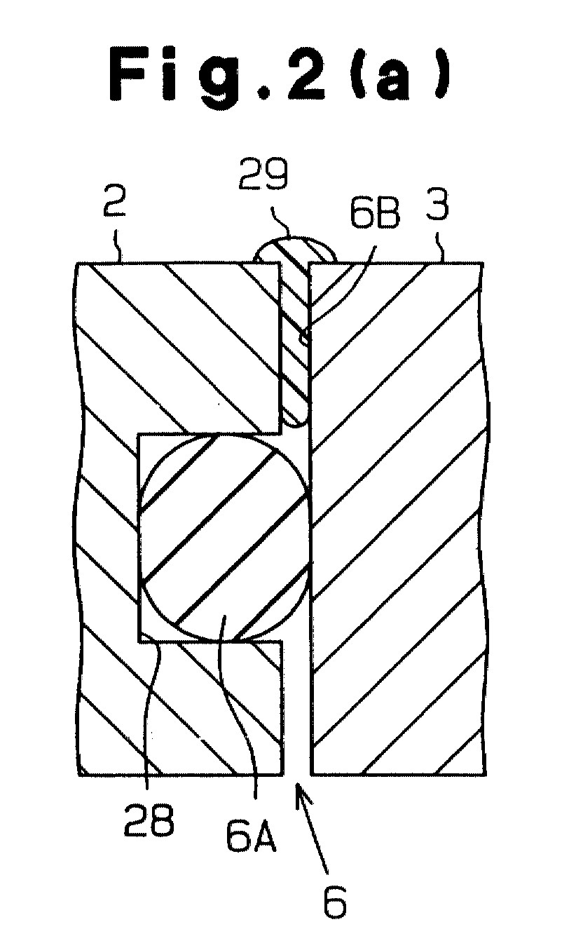
As illustrated in Fig. 2(a), a first seal ring 6A is
fitted in a groove 28 formed in the front housing member 2,
which is joined with the cylinder block 3. The opening of
the groove 28 is covered with the cylinder block 3.
-
A slight gap 6B is formed between the front housing
member 2 and the cylinder block 3 for possible dimensional
errors in the front housing member 2 and the cylinder block
3 and for reasons of an intended design. A resin 29 adheres
to a joint 6 between the front housing member 2 and the
cylinder block 3 for filling the gap 6B. Some of the resin
29 enters the gap 6B. The remainder of the resin 29 swells
from the front housing member 2 and the cylinder block 3 as
illustrated.
-
As illustrated in Fig. 2(b), a second seal ring 7A is
fitted in a groove 50 formed in the rear housing member 4,
which is joined with the cylinder block 3. The opening of
the groove 50 is covered with the cylinder block 3.
-
A slight gap 7B is formed between the cylinder block 3
and the rear housing member 4 for dimensional errors of the
cylinder block 3 and the rear housing member 4 and for
reasons of an intended design. A resin 29 adheres to a
joint 7 between the cylinder block 3 and the rear housing
member 4 for filling the gap 7B. Some of the resin 29
enters the gap 7B. The remainder of the resin 29 swells
from the cylinder block 3 and the rear housing member 4 as
shown. The resin 29 should be such one that resists
penetration by carbon dioxide. Preferably, nylon 66 or high
acrylonitrile containing polymer resin, for example, may be
used for the resin 29.
-
In the foregoing embodiment, the following advantages
are provided.
-
The resin 29 adhering to the joints 6, 7 fills the gaps
6B, 7B. Since the resin 29 resists penetration by carbon
dioxide, the carbon dioxide is prevented from leaking from
the compressor 1.
-
Since the resin 29 forms a good seal, only one of the
seal rings 6A, 7A, which have a relatively small cross
sections, is required for each joint 6, 7. This results in
a simple structure of both joints 6, 7 and a smaller size of
the compressor 1.
-
The resin 29 is chosen to resist penetration by gas.
Therefore, both ring seals 6, 7 may be formed of a material
that is highly penetrable to a gas. For example, it is
possible to select nitrile rubber as the material of both
seal rings 6A, 7A. Nitrile rubber is resistant to heat and
oil, less prone to the formation of blisters, and
inexpensive. This reduces the cost of the seal rings 6A, 7A.
-
The resin 29 is applied to the joints 6, 7 from the
outside of the compressor 1. Therefore, the operation of
installing the seal is relatively simple which lowers costs.
-
The foregoing embodiment may be modified, for example,
in the following manner.
-
As can be seen in a second embodiment illustrated in
Fig. 3(a), a third embodiment in Fig. 3(b), and a fourth
embodiment in Fig. 3(c), a portion of the joint 6 may be
formed as a cavity 30, 31 or 32, which is filled by the
resin 29. The joint 7 may be formed in a manner similar to
the joint 6. In this way, the resin 29 can be introduced
securely between the cylinder block 3 and the front housing
member 2 or between the cylinder block 3 and the rear
housing member 4. This improves the seal and the efficiency
of the application of the resin 29.
-
In the embodiments illustrated in Figs. 3(a) and 3(c),
the cavities 30, 32 diverge toward the outside of the
compressor 1. This shape facilitates the application of the
resin 29 into the corresponding cavities 30, 32.
-
In the structure illustrated in Fig. 3(b), at the
outside of the respective seal rings 6A, 7A in the radial
direction, the cylinder block 3 abuts against the front
housing member 2, and the cylinder block 3 abuts against the
rear housing member 4, and a filler 31 is formed outside of
the abutment in the radial direction. In this structure,
the joints 6, 7 are sealed by the contact between the
cylinder block 3 and the front housing member 2 and the
contact between the cylinder block 3 and the rear housing
member 4 and by the seal rings 6A, 7A and the resin 29.
Thus, the seals are further improved.
-
As can be seen in a fifth embodiment illustrated in Fig.
3(d), the resin 29 may hardly enter the joints 6, 7. A
majority of the resin 29 remains on the surface of the
housing. In this embodiment, the resin 29 can be applied by
spraying, to improve efficiency.
-
In a sixth embodiment illustrated in Fig. 3(e), the
valve plate assembly 5 has the same diameter as that of the
housing. The valve plate assembly 5 includes a main plate
40, which includes suction ports 23 and discharge ports 25,
a first subplate 41, which includes suction valves 22, and a
second subplate 42, which includes discharge valves 24. The
valve plate assembly 5 is sandwiched by two gaskets 43 made
of rubber. One gasket 43 is located between the cylinder
block 3 and the first subplate 41, and the other gasket 43
is located between the rear housing member 4 and the second
subplate 42. The resin 29 is applied to cover the joints on
the surface of the housing of the compressor. Refrigerant
gas is prevented from leaking to the outside of the
compressor 1 by the resin 29.
-
In the embodiment of Fig. 3(e), the resin 29 need not
radially enter a gap between adjacent parts. In this way,
the resin 29 can be applied by spraying from the outside,
thereby improving efficiency.
-
The refrigerant gas may be, for example, freon gas. In
this case, the preferred resin 29 is one that resists
penetration by freon gas.
-
The present invention is not limited to housings of
compressors and may be applied to the housings of any
equipment.
-
Therefore, the present examples and embodiments are to
be considered as illustrative and not restrictive and the
invention is not to be limited to the details given herein,
but may be modified within the scope and equivalence of the
applied claims.
-
An improved housing seal. Resin (29) is applied to the
outer surface of a joint between adjacent housing members (2,
3, 4). This produces an effective, simple in structure, and
inexpensive seal that limits the size of the housing.