EP1161915A2 - Luftströmungskanal - Google Patents
Luftströmungskanal Download PDFInfo
- Publication number
- EP1161915A2 EP1161915A2 EP01107221A EP01107221A EP1161915A2 EP 1161915 A2 EP1161915 A2 EP 1161915A2 EP 01107221 A EP01107221 A EP 01107221A EP 01107221 A EP01107221 A EP 01107221A EP 1161915 A2 EP1161915 A2 EP 1161915A2
- Authority
- EP
- European Patent Office
- Prior art keywords
- air flow
- flow channel
- structuring
- air
- suction
- Prior art date
- Legal status (The legal status is an assumption and is not a legal conclusion. Google has not performed a legal analysis and makes no representation as to the accuracy of the status listed.)
- Granted
Links
Images


Classifications
-
- F—MECHANICAL ENGINEERING; LIGHTING; HEATING; WEAPONS; BLASTING
- F15—FLUID-PRESSURE ACTUATORS; HYDRAULICS OR PNEUMATICS IN GENERAL
- F15D—FLUID DYNAMICS, i.e. METHODS OR MEANS FOR INFLUENCING THE FLOW OF GASES OR LIQUIDS
- F15D1/00—Influencing flow of fluids
- F15D1/02—Influencing flow of fluids in pipes or conduits
- F15D1/06—Influencing flow of fluids in pipes or conduits by influencing the boundary layer
- F15D1/065—Whereby an element is dispersed in a pipe over the whole length or whereby several elements are regularly distributed in a pipe
-
- A—HUMAN NECESSITIES
- A47—FURNITURE; DOMESTIC ARTICLES OR APPLIANCES; COFFEE MILLS; SPICE MILLS; SUCTION CLEANERS IN GENERAL
- A47L—DOMESTIC WASHING OR CLEANING; SUCTION CLEANERS IN GENERAL
- A47L9/00—Details or accessories of suction cleaners, e.g. mechanical means for controlling the suction or for effecting pulsating action; Storing devices specially adapted to suction cleaners or parts thereof; Carrying-vehicles specially adapted for suction cleaners
- A47L9/0072—Mechanical means for controlling the suction or for effecting pulsating action
-
- A—HUMAN NECESSITIES
- A47—FURNITURE; DOMESTIC ARTICLES OR APPLIANCES; COFFEE MILLS; SPICE MILLS; SUCTION CLEANERS IN GENERAL
- A47L—DOMESTIC WASHING OR CLEANING; SUCTION CLEANERS IN GENERAL
- A47L9/00—Details or accessories of suction cleaners, e.g. mechanical means for controlling the suction or for effecting pulsating action; Storing devices specially adapted to suction cleaners or parts thereof; Carrying-vehicles specially adapted for suction cleaners
- A47L9/0081—Means for exhaust-air diffusion; Means for sound or vibration damping
-
- A—HUMAN NECESSITIES
- A47—FURNITURE; DOMESTIC ARTICLES OR APPLIANCES; COFFEE MILLS; SPICE MILLS; SUCTION CLEANERS IN GENERAL
- A47L—DOMESTIC WASHING OR CLEANING; SUCTION CLEANERS IN GENERAL
- A47L9/00—Details or accessories of suction cleaners, e.g. mechanical means for controlling the suction or for effecting pulsating action; Storing devices specially adapted to suction cleaners or parts thereof; Carrying-vehicles specially adapted for suction cleaners
- A47L9/02—Nozzles
-
- A—HUMAN NECESSITIES
- A47—FURNITURE; DOMESTIC ARTICLES OR APPLIANCES; COFFEE MILLS; SPICE MILLS; SUCTION CLEANERS IN GENERAL
- A47L—DOMESTIC WASHING OR CLEANING; SUCTION CLEANERS IN GENERAL
- A47L9/00—Details or accessories of suction cleaners, e.g. mechanical means for controlling the suction or for effecting pulsating action; Storing devices specially adapted to suction cleaners or parts thereof; Carrying-vehicles specially adapted for suction cleaners
- A47L9/24—Hoses or pipes; Hose or pipe couplings
Definitions
- the invention relates to an air flow channel Household suction device or blower, in particular of a vacuum cleaner.
- suction and blowing channels match the design of the interior and external functional elements such as constrictions, curves, standardized interfaces etc. must be adapted and on the other hand should be designed to be inexpensive to manufacture, smooth, easily removable surfaces are preferred. Such surfaces in combination with secondary ones
- requirements lead to the disadvantage that a sequence of zones of different flow velocities leads to loss of performance.
- Noise emission There are also disadvantages Erosion and / or cavitation in the impact areas.
- This task is initially and essentially through the subject of claim 1 by one to one Micro-swirling structuring of the inner wall of the air flow channel released.
- this Design is an increased efficiency of the household suction device achieved.
- the noise emission reduced as well as the influences of manufacturing-related Reduced inaccuracies. Deposits and abrasion are reduced.
- Structuring the inner wall of the air flow channel air performance is equally high on the suction or blowing nozzle with reduced absorption capacity of up to 20%.
- the inner wall of the air flow channel has according to the invention a structuring on that the micro-vortex favors and macro turbulence or dead water areas suppressed.
- the structuring can be borrowed from nature or be freely constructed and by means of photography, Etching, blasting, embossing, laminating, painting or generated directly using rapid prototyping, so that the structuring can be reproduced as required is. You can use tools for shaping Methods such as B. injection molding, embossing or sintering be transmitted.
- the invention also provided that a common, standard air flow channel with one that induces micro-swirling Plastic film is glued.
- the structure is scaled. So the structuring can approximate the surface of the Represent the skin of large fish, with this further Structuring provided partially or over the entire area can be. It is also conceivable that the structuring is formed like a groove.
- Fig. 1 Is shown and described initially with reference to Fig. 1 is a household appliance in the form of a vacuum cleaner 1, with a suction / blower motor 2 and an associated Suction nozzle 3.
- the suction air inlet formed in the suction nozzle 3 is provided with the reference symbol 3 '. Starting from this extends an air flow channel 4 - when arranged the suction nozzle 3 on the vacuum cleaner 1- essentially to a suction air inlet 2 'of the suction / blower motor 2nd
- Both the vacuum cleaner 1 and the suction nozzle 3 each have an air flow channel 4, through which the aspirated medium, one on the motor housing 5 docked filter, not shown, flowing through is directed.
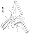
- FIG. 2 is a portion of an air flow channel 4 shown in a schematic sectional view.
- the inner wall 6 of the air flow channel 4 provided with a structure 7, which in suction or blowing operation to a micro swirl of the medium being passed.
- This structuring can be photographed, etched, blasted, Embossing, laminating or painting or by means of Rapid prototyping can be generated directly.
- the surface of the inner wall 6 thus created of the air flow channel 4 becomes a micro swirl favored, however, a macro vortex or dead water areas suppressed so that with the same power consumption of the suction / blower motor 2 an increased air output or a reduced one with the same high air output Recording performance is achieved.
- Shaping is through the micro-swirling an air cushion in the area of the inner wall surface created, which an undisturbed flow of Medium 8 supported in the air flow channel 4 (see Fig. 3).
- the structure 7 is formed like a scale with an orientation pointing in the flow direction r of the individual scales. These scales point further a substructuring 7 'according to FIG. 5. How to can recognize this substructuring 7 'by circular segment-shaped, if necessary, interlocking Grooves are formed.
Landscapes
- Engineering & Computer Science (AREA)
- Mechanical Engineering (AREA)
- Physics & Mathematics (AREA)
- Fluid Mechanics (AREA)
- General Engineering & Computer Science (AREA)
- Structures Of Non-Positive Displacement Pumps (AREA)
- Exhaust Gas After Treatment (AREA)
- Infusion, Injection, And Reservoir Apparatuses (AREA)
- Fluid-Pressure Circuits (AREA)
- Jet Pumps And Other Pumps (AREA)
- Nozzles For Electric Vacuum Cleaners (AREA)
- Filtering Of Dispersed Particles In Gases (AREA)
Abstract
Description
- Fig. 1
- ein Haushaltssauggerät in Form eines Staubsauggeräts in perspektivischer Darstellung;
- Fig. 2
- eine schematische Teildarstellung eines, die erfindungsgemäße, innenwandungsseitige Strukturierung aufweisenden Luftströmungskanals;
- Fig. 3
- eine schematische Schnittdarstellung gemäß der Linie III-III in Fig. 2;
- Fig. 4
- eine Herausvergrößerung des Bereiches IV in Fig. 2;
- Fig. 5
- eine mikroskopische Vergrößerung des Bereiches V in Fig. 4;
- Fig. 6
- eine Ansicht gegen das, einen erfindungsgemäßen Luftströmungskanal aufweisenden Motor-/Filter-Gehäuse des Staubsauggerätes gemäß Fig. 1;
- Fig. 7
- eine perspektivische Darstellung einer Saugdüse des Staubsauggerätes;
- Fig. 8
- eine partiell geschnittene, perspektivische Prinzipdarstellung einer Saugdüse mit einem, die erfindungsgemäße Strukturierung aufweisendem Luftströmungskanal.
Claims (7)
- Luftströmungskanal (4) eines Haushaltssauggerätes oder -blasgerätes, insbesondere eines Staubsauggerätes (1), gekennzeichnet durch eine zu einer Mikroverwirbelung führende Strukturierung der Innenwandung des Luftströmungskanales (4).
- Luftströmungskanal nach Anspruch 1 oder insbesondere danach, dadurch gekennzeichnet, dass die Strukturierung schuppenartig ausgebildet ist.
- Luftströmungskanal nach einem oder mehreren der vorhergehenden Ansprüche oder insbesondere danach, dadurch gekennzeichnet, dass die Strukturierung rillenartig ausgebildet ist.
- Luftströmungskanal nach einem oder mehreren der vorhergehenden Ansprüche oder insbesondere danach, dadurch gekennzeichnet, dass die Strukturierung ungeordnet ausgebildet ist.
- Luftströmungskanal nach einem oder mehreren der vorhergehenden Ansprüche oder insbesondere danach, dadurch gekennzeichnet, dass die Strukturierung auf dem größten Teil der Innenwandung (6) des Luftströmungskanales (4) von einem Sauglufteinlass (3') bis zum Saugluftgebläseeinlass (2') ausgebildet ist.
- Luftströmungskanal nach einem oder mehreren der vorhergehenden Ansprüche oder insbesondere danach, dadurch gekennzeichnet, dass die Strukturierung auf dem größten Teil der Innenwandung (6) des Luftströmungskanales (4) von einem Blasluftgebläseauslass bis zu einem Blasluftauslass ausgebildet ist.
- Luftströmungskanal nach einem oder mehreren der vorhergehenden Ansprüche oder insbesondere danach, dadurch gekennzeichnet, dass die Strukturierung im Hundertstel- bis Zehntel-Millimeter-Bereich ausgebildet ist.
Priority Applications (1)
| Application Number | Priority Date | Filing Date | Title |
|---|---|---|---|
| SI200130666T SI1161915T1 (sl) | 2000-04-18 | 2001-03-23 | Kanal zracnega toka |
Applications Claiming Priority (4)
| Application Number | Priority Date | Filing Date | Title |
|---|---|---|---|
| DE10019125 | 2000-04-18 | ||
| DE10019125 | 2000-04-18 | ||
| DE10023408A DE10023408A1 (de) | 2000-04-18 | 2000-05-12 | Luftströmungskanal |
| DE10023408 | 2000-05-12 |
Publications (3)
| Publication Number | Publication Date |
|---|---|
| EP1161915A2 true EP1161915A2 (de) | 2001-12-12 |
| EP1161915A3 EP1161915A3 (de) | 2005-04-20 |
| EP1161915B1 EP1161915B1 (de) | 2006-10-04 |
Family
ID=26005361
Family Applications (1)
| Application Number | Title | Priority Date | Filing Date |
|---|---|---|---|
| EP01107221A Expired - Lifetime EP1161915B1 (de) | 2000-04-18 | 2001-03-23 | Luftströmungskanal |
Country Status (4)
| Country | Link |
|---|---|
| EP (1) | EP1161915B1 (de) |
| AT (1) | ATE341268T1 (de) |
| DE (1) | DE50111125D1 (de) |
| ES (1) | ES2270913T3 (de) |
Cited By (1)
| Publication number | Priority date | Publication date | Assignee | Title |
|---|---|---|---|---|
| CN106949099A (zh) * | 2017-04-28 | 2017-07-14 | 苏州市海朋电子商务有限公司 | 吸尘器用电机风泵 |
Families Citing this family (2)
| Publication number | Priority date | Publication date | Assignee | Title |
|---|---|---|---|---|
| US20050081321A1 (en) | 2003-10-15 | 2005-04-21 | Milligan Michael A. | Hand-held cordless vacuum cleaner |
| ATE460108T1 (de) | 2006-01-27 | 2010-03-15 | Black & Decker Inc | Filterreinigungsmechanismus von staubsauger |
Family Cites Families (6)
| Publication number | Priority date | Publication date | Assignee | Title |
|---|---|---|---|---|
| FR685301A (fr) * | 1929-11-23 | 1930-07-09 | Tuyau à surface intérieure à gradins | |
| DE2615507A1 (de) * | 1976-04-09 | 1977-10-20 | Mauz & Pfeiffer Progress | Staubsauger, insbesondere elektrisch betriebener haushaltstaubsauger |
| JP3047984B2 (ja) * | 1990-04-18 | 2000-06-05 | 株式会社日立製作所 | 電気掃除機 |
| US5067584A (en) * | 1990-04-25 | 1991-11-26 | Williams William H | Low cost replaceable type sound dampening unit for vacuum cleaning machine |
| KR0136305Y1 (ko) * | 1996-09-10 | 1999-02-01 | 최진호 | 진공청소기의 흡입구체 |
| DE19836873A1 (de) * | 1998-06-24 | 1999-12-30 | Montaplast Gmbh | Fluidführungselement für Wärmekraftmaschinen mit strömungstechnisch optimierter Oberflächenstruktur |
-
2001
- 2001-03-23 AT AT01107221T patent/ATE341268T1/de not_active IP Right Cessation
- 2001-03-23 ES ES01107221T patent/ES2270913T3/es not_active Expired - Lifetime
- 2001-03-23 EP EP01107221A patent/EP1161915B1/de not_active Expired - Lifetime
- 2001-03-23 DE DE50111125T patent/DE50111125D1/de not_active Expired - Fee Related
Cited By (2)
| Publication number | Priority date | Publication date | Assignee | Title |
|---|---|---|---|---|
| CN106949099A (zh) * | 2017-04-28 | 2017-07-14 | 苏州市海朋电子商务有限公司 | 吸尘器用电机风泵 |
| CN106949099B (zh) * | 2017-04-28 | 2019-05-10 | 苏州市海朋电子商务有限公司 | 吸尘器用电机风泵 |
Also Published As
| Publication number | Publication date |
|---|---|
| EP1161915A3 (de) | 2005-04-20 |
| ATE341268T1 (de) | 2006-10-15 |
| DE50111125D1 (de) | 2006-11-16 |
| EP1161915B1 (de) | 2006-10-04 |
| ES2270913T3 (es) | 2007-04-16 |
Similar Documents
| Publication | Publication Date | Title |
|---|---|---|
| DE102008056459A1 (de) | Diagonallüfter | |
| DE102015017008A1 (de) | Auslassvorrichtung | |
| DE19903165A1 (de) | Ansaugvorrichtung mit einem Durchbrüche aufweisenden Leitungsabschnitt | |
| EP1219837A2 (de) | Lüfter mit Axialschlaufen | |
| EP0702105B1 (de) | Gehäuse für ein Gebläse einem Haushaltgerät, insbesondere in einem Haushalt-Wäschetrockner | |
| EP2282135B1 (de) | Ventilator | |
| EP2455665A2 (de) | Gasturbinenbrennkammer mit einer Kühlluftzuführvorrichtung | |
| DE1072024B (de) | Vorrichtung zur Umwand lung der kinetischen Energie eines Wirbels in Druck | |
| DE212019000325U1 (de) | Zerkleinerungs- und Verfeinerungsstruktur vom progressiven Perforationstyp | |
| EP1493998A2 (de) | Ultraschallzähler zur Bestimmung der Durchflussmenge eines strömenden Mediums | |
| EP3234337A1 (de) | Luftleitung für einen ansaugtrakt einer verbrennungskraftmaschine, insbesondere eines kraftwagens | |
| DE102012216138A1 (de) | Lufteinlassvorrichtung für ein Fahrzeug | |
| EP1706595A1 (de) | Strömungsmaschine mit einem im gehäusemittelteil vorgesehenen spiralkanal | |
| DE102007019538A1 (de) | Luftführungselement für eine Flugzeugklimaanlage | |
| EP1923576B1 (de) | Rohrbogen für Fluidkanäle | |
| EP3114354A1 (de) | Lüfterrad eines axiallüfters | |
| DE102021119121A1 (de) | Radial- oder Diagonallaufrad mit modifizierter Schaufelkante | |
| EP1161915B1 (de) | Luftströmungskanal | |
| EP1081385A1 (de) | Förderpumpe | |
| DE10023408A1 (de) | Luftströmungskanal | |
| DE20010099U1 (de) | Strahlregler | |
| EP0408956B1 (de) | Flügelrad | |
| DE102008053065A1 (de) | Klappenanordnung | |
| WO2005118968A1 (de) | Sanitäre einsetzeinheit | |
| EP2072392B1 (de) | Bootsantriebsschraube |
Legal Events
| Date | Code | Title | Description |
|---|---|---|---|
| PUAI | Public reference made under article 153(3) epc to a published international application that has entered the european phase |
Free format text: ORIGINAL CODE: 0009012 |
|
| AK | Designated contracting states |
Kind code of ref document: A2 Designated state(s): AT BE CH CY DE DK ES FI FR GB GR IE IT LI LU MC NL PT SE TR |
|
| AX | Request for extension of the european patent |
Free format text: AL;LT;LV;MK;RO;SI |
|
| PUAL | Search report despatched |
Free format text: ORIGINAL CODE: 0009013 |
|
| AK | Designated contracting states |
Kind code of ref document: A3 Designated state(s): AT BE CH CY DE DK ES FI FR GB GR IE IT LI LU MC NL PT SE TR |
|
| AX | Request for extension of the european patent |
Extension state: AL LT LV MK RO SI |
|
| RIC1 | Information provided on ipc code assigned before grant |
Ipc: 7A 47L 5/28 B Ipc: 7F 15D 1/06 B Ipc: 7F 15D 1/02 B Ipc: 7A 47L 9/24 B Ipc: 7A 47L 9/00 A |
|
| 17P | Request for examination filed |
Effective date: 20050930 |
|
| AKX | Designation fees paid |
Designated state(s): AT BE CH CY DE DK ES FI FR GB GR IE IT LI LU MC NL PT SE TR |
|
| AXX | Extension fees paid |
Extension state: SI Payment date: 20050930 |
|
| GRAP | Despatch of communication of intention to grant a patent |
Free format text: ORIGINAL CODE: EPIDOSNIGR1 |
|
| GRAS | Grant fee paid |
Free format text: ORIGINAL CODE: EPIDOSNIGR3 |
|
| GRAA | (expected) grant |
Free format text: ORIGINAL CODE: 0009210 |
|
| AK | Designated contracting states |
Kind code of ref document: B1 Designated state(s): AT BE CH CY DE DK ES FI FR GB GR IE IT LI LU MC NL PT SE TR |
|
| AX | Request for extension of the european patent |
Extension state: SI |
|
| PG25 | Lapsed in a contracting state [announced via postgrant information from national office to epo] |
Ref country code: IT Free format text: LAPSE BECAUSE OF FAILURE TO SUBMIT A TRANSLATION OF THE DESCRIPTION OR TO PAY THE FEE WITHIN THE PRESCRIBED TIME-LIMIT;WARNING: LAPSES OF ITALIAN PATENTS WITH EFFECTIVE DATE BEFORE 2007 MAY HAVE OCCURRED AT ANY TIME BEFORE 2007. THE CORRECT EFFECTIVE DATE MAY BE DIFFERENT FROM THE ONE RECORDED. Effective date: 20061004 Ref country code: IE Free format text: LAPSE BECAUSE OF FAILURE TO SUBMIT A TRANSLATION OF THE DESCRIPTION OR TO PAY THE FEE WITHIN THE PRESCRIBED TIME-LIMIT Effective date: 20061004 Ref country code: FI Free format text: LAPSE BECAUSE OF FAILURE TO SUBMIT A TRANSLATION OF THE DESCRIPTION OR TO PAY THE FEE WITHIN THE PRESCRIBED TIME-LIMIT Effective date: 20061004 |
|
| REG | Reference to a national code |
Ref country code: GB Ref legal event code: FG4D Free format text: NOT ENGLISH |
|
| GBT | Gb: translation of ep patent filed (gb section 77(6)(a)/1977) |
Effective date: 20061004 |
|
| REG | Reference to a national code |
Ref country code: CH Ref legal event code: EP |
|
| REG | Reference to a national code |
Ref country code: IE Ref legal event code: FG4D Free format text: LANGUAGE OF EP DOCUMENT: GERMAN |
|
| REF | Corresponds to: |
Ref document number: 50111125 Country of ref document: DE Date of ref document: 20061116 Kind code of ref document: P |
|
| REG | Reference to a national code |
Ref country code: SE Ref legal event code: TRGR |
|
| PG25 | Lapsed in a contracting state [announced via postgrant information from national office to epo] |
Ref country code: DK Free format text: LAPSE BECAUSE OF FAILURE TO SUBMIT A TRANSLATION OF THE DESCRIPTION OR TO PAY THE FEE WITHIN THE PRESCRIBED TIME-LIMIT Effective date: 20070104 |
|
| ET | Fr: translation filed | ||
| PG25 | Lapsed in a contracting state [announced via postgrant information from national office to epo] |
Ref country code: PT Free format text: LAPSE BECAUSE OF FAILURE TO SUBMIT A TRANSLATION OF THE DESCRIPTION OR TO PAY THE FEE WITHIN THE PRESCRIBED TIME-LIMIT Effective date: 20070316 |
|
| REG | Reference to a national code |
Ref country code: ES Ref legal event code: FG2A Ref document number: 2270913 Country of ref document: ES Kind code of ref document: T3 |
|
| REG | Reference to a national code |
Ref country code: IE Ref legal event code: FD4D |
|
| PLBE | No opposition filed within time limit |
Free format text: ORIGINAL CODE: 0009261 |
|
| STAA | Information on the status of an ep patent application or granted ep patent |
Free format text: STATUS: NO OPPOSITION FILED WITHIN TIME LIMIT |
|
| 26N | No opposition filed |
Effective date: 20070705 |
|
| REG | Reference to a national code |
Ref country code: CH Ref legal event code: PL |
|
| BERE | Be: lapsed |
Owner name: VORWERK & CO. INTERHOLDING G.M.B.H. Effective date: 20070331 |
|
| PG25 | Lapsed in a contracting state [announced via postgrant information from national office to epo] |
Ref country code: BE Free format text: LAPSE BECAUSE OF NON-PAYMENT OF DUE FEES Effective date: 20070331 |
|
| PG25 | Lapsed in a contracting state [announced via postgrant information from national office to epo] |
Ref country code: MC Free format text: LAPSE BECAUSE OF NON-PAYMENT OF DUE FEES Effective date: 20070331 |
|
| PG25 | Lapsed in a contracting state [announced via postgrant information from national office to epo] |
Ref country code: LI Free format text: LAPSE BECAUSE OF NON-PAYMENT OF DUE FEES Effective date: 20070331 Ref country code: CH Free format text: LAPSE BECAUSE OF NON-PAYMENT OF DUE FEES Effective date: 20070331 |
|
| PG25 | Lapsed in a contracting state [announced via postgrant information from national office to epo] |
Ref country code: GR Free format text: LAPSE BECAUSE OF FAILURE TO SUBMIT A TRANSLATION OF THE DESCRIPTION OR TO PAY THE FEE WITHIN THE PRESCRIBED TIME-LIMIT Effective date: 20070105 |
|
| PGFP | Annual fee paid to national office [announced via postgrant information from national office to epo] |
Ref country code: GB Payment date: 20080311 Year of fee payment: 8 Ref country code: NL Payment date: 20080307 Year of fee payment: 8 Ref country code: SE Payment date: 20080311 Year of fee payment: 8 |
|
| PGFP | Annual fee paid to national office [announced via postgrant information from national office to epo] |
Ref country code: AT Payment date: 20080307 Year of fee payment: 8 |
|
| PGFP | Annual fee paid to national office [announced via postgrant information from national office to epo] |
Ref country code: DE Payment date: 20080307 Year of fee payment: 8 Ref country code: ES Payment date: 20080307 Year of fee payment: 8 Ref country code: FR Payment date: 20080305 Year of fee payment: 8 |
|
| PGFP | Annual fee paid to national office [announced via postgrant information from national office to epo] |
Ref country code: IT Payment date: 20080328 Year of fee payment: 8 Ref country code: TR Payment date: 20080311 Year of fee payment: 8 |
|
| PG25 | Lapsed in a contracting state [announced via postgrant information from national office to epo] |
Ref country code: CY Free format text: LAPSE BECAUSE OF FAILURE TO SUBMIT A TRANSLATION OF THE DESCRIPTION OR TO PAY THE FEE WITHIN THE PRESCRIBED TIME-LIMIT Effective date: 20061004 Ref country code: LU Free format text: LAPSE BECAUSE OF NON-PAYMENT OF DUE FEES Effective date: 20070323 |
|
| PG25 | Lapsed in a contracting state [announced via postgrant information from national office to epo] |
Ref country code: AT Free format text: LAPSE BECAUSE OF NON-PAYMENT OF DUE FEES Effective date: 20090323 |
|
| EUG | Se: european patent has lapsed | ||
| GBPC | Gb: european patent ceased through non-payment of renewal fee |
Effective date: 20090323 |
|
| NLV4 | Nl: lapsed or anulled due to non-payment of the annual fee |
Effective date: 20091001 |
|
| REG | Reference to a national code |
Ref country code: FR Ref legal event code: ST Effective date: 20091130 |
|
| PG25 | Lapsed in a contracting state [announced via postgrant information from national office to epo] |
Ref country code: DE Free format text: LAPSE BECAUSE OF NON-PAYMENT OF DUE FEES Effective date: 20091001 |
|
| REG | Reference to a national code |
Ref country code: SI Ref legal event code: KO00 Effective date: 20091211 |
|
| PG25 | Lapsed in a contracting state [announced via postgrant information from national office to epo] |
Ref country code: NL Free format text: LAPSE BECAUSE OF NON-PAYMENT OF DUE FEES Effective date: 20091001 |
|
| PG25 | Lapsed in a contracting state [announced via postgrant information from national office to epo] |
Ref country code: GB Free format text: LAPSE BECAUSE OF NON-PAYMENT OF DUE FEES Effective date: 20090323 Ref country code: FR Free format text: LAPSE BECAUSE OF NON-PAYMENT OF DUE FEES Effective date: 20091123 |
|
| REG | Reference to a national code |
Ref country code: ES Ref legal event code: FD2A Effective date: 20090324 |
|
| PG25 | Lapsed in a contracting state [announced via postgrant information from national office to epo] |
Ref country code: ES Free format text: LAPSE BECAUSE OF NON-PAYMENT OF DUE FEES Effective date: 20090324 |
|
| PG25 | Lapsed in a contracting state [announced via postgrant information from national office to epo] |
Ref country code: IT Free format text: LAPSE BECAUSE OF NON-PAYMENT OF DUE FEES Effective date: 20090323 |
|
| PG25 | Lapsed in a contracting state [announced via postgrant information from national office to epo] |
Ref country code: SE Free format text: LAPSE BECAUSE OF NON-PAYMENT OF DUE FEES Effective date: 20090324 |
|
| PG25 | Lapsed in a contracting state [announced via postgrant information from national office to epo] |
Ref country code: TR Free format text: LAPSE BECAUSE OF NON-PAYMENT OF DUE FEES Effective date: 20090323 |