EP1160960B1 - Explosionsgeschützte Motoranordnung - Google Patents
Explosionsgeschützte Motoranordnung Download PDFInfo
- Publication number
- EP1160960B1 EP1160960B1 EP01107240A EP01107240A EP1160960B1 EP 1160960 B1 EP1160960 B1 EP 1160960B1 EP 01107240 A EP01107240 A EP 01107240A EP 01107240 A EP01107240 A EP 01107240A EP 1160960 B1 EP1160960 B1 EP 1160960B1
- Authority
- EP
- European Patent Office
- Prior art keywords
- arrangement according
- rotor
- motor arrangement
- motor
- galvanomagnetic
- Prior art date
- Legal status (The legal status is an assumption and is not a legal conclusion. Google has not performed a legal analysis and makes no representation as to the accuracy of the status listed.)
- Expired - Lifetime
Links
- 238000004880 explosion Methods 0.000 title 1
- 238000004804 winding Methods 0.000 claims description 15
- 239000004033 plastic Substances 0.000 claims description 10
- 229920003023 plastic Polymers 0.000 claims description 10
- 238000004382 potting Methods 0.000 claims description 8
- 150000001875 compounds Chemical class 0.000 claims description 7
- 239000000463 material Substances 0.000 claims description 6
- 230000005291 magnetic effect Effects 0.000 claims description 4
- OKTJSMMVPCPJKN-UHFFFAOYSA-N Carbon Chemical compound [C] OKTJSMMVPCPJKN-UHFFFAOYSA-N 0.000 claims 1
- XEEYBQQBJWHFJM-UHFFFAOYSA-N Iron Chemical group [Fe] XEEYBQQBJWHFJM-UHFFFAOYSA-N 0.000 claims 1
- 229910052799 carbon Inorganic materials 0.000 claims 1
- 230000005294 ferromagnetic effect Effects 0.000 claims 1
- 238000009413 insulation Methods 0.000 description 9
- 238000002955 isolation Methods 0.000 description 8
- 239000002360 explosive Substances 0.000 description 3
- 230000004888 barrier function Effects 0.000 description 2
- 238000012986 modification Methods 0.000 description 2
- 230000004048 modification Effects 0.000 description 2
- 229920000049 Carbon (fiber) Polymers 0.000 description 1
- FYYHWMGAXLPEAU-UHFFFAOYSA-N Magnesium Chemical compound [Mg] FYYHWMGAXLPEAU-UHFFFAOYSA-N 0.000 description 1
- XAGFODPZIPBFFR-UHFFFAOYSA-N aluminium Chemical compound [Al] XAGFODPZIPBFFR-UHFFFAOYSA-N 0.000 description 1
- 229910052782 aluminium Inorganic materials 0.000 description 1
- 239000003990 capacitor Substances 0.000 description 1
- 239000004917 carbon fiber Substances 0.000 description 1
- 230000001419 dependent effect Effects 0.000 description 1
- 238000011161 development Methods 0.000 description 1
- 230000018109 developmental process Effects 0.000 description 1
- 230000000694 effects Effects 0.000 description 1
- 239000003302 ferromagnetic material Substances 0.000 description 1
- 230000004907 flux Effects 0.000 description 1
- 238000009499 grossing Methods 0.000 description 1
- 238000003475 lamination Methods 0.000 description 1
- 229910052749 magnesium Inorganic materials 0.000 description 1
- 239000011777 magnesium Substances 0.000 description 1
- 238000000034 method Methods 0.000 description 1
- 239000000203 mixture Substances 0.000 description 1
- 230000035515 penetration Effects 0.000 description 1
- 238000000926 separation method Methods 0.000 description 1
- 230000003068 static effect Effects 0.000 description 1
- 239000000126 substance Substances 0.000 description 1
- 238000009423 ventilation Methods 0.000 description 1
Images

Classifications
-
- F—MECHANICAL ENGINEERING; LIGHTING; HEATING; WEAPONS; BLASTING
- F04—POSITIVE - DISPLACEMENT MACHINES FOR LIQUIDS; PUMPS FOR LIQUIDS OR ELASTIC FLUIDS
- F04D—NON-POSITIVE-DISPLACEMENT PUMPS
- F04D25/00—Pumping installations or systems
- F04D25/02—Units comprising pumps and their driving means
- F04D25/06—Units comprising pumps and their driving means the pump being electrically driven
- F04D25/0606—Units comprising pumps and their driving means the pump being electrically driven the electric motor being specially adapted for integration in the pump
- F04D25/0613—Units comprising pumps and their driving means the pump being electrically driven the electric motor being specially adapted for integration in the pump the electric motor being of the inside-out type, i.e. the rotor is arranged radially outside a central stator
- F04D25/0633—Details of the magnetic circuit
-
- H—ELECTRICITY
- H02—GENERATION; CONVERSION OR DISTRIBUTION OF ELECTRIC POWER
- H02K—DYNAMO-ELECTRIC MACHINES
- H02K29/00—Motors or generators having non-mechanical commutating devices, e.g. discharge tubes or semiconductor devices
- H02K29/06—Motors or generators having non-mechanical commutating devices, e.g. discharge tubes or semiconductor devices with position sensing devices
- H02K29/08—Motors or generators having non-mechanical commutating devices, e.g. discharge tubes or semiconductor devices with position sensing devices using magnetic effect devices, e.g. Hall-plates, magneto-resistors
-
- H—ELECTRICITY
- H02—GENERATION; CONVERSION OR DISTRIBUTION OF ELECTRIC POWER
- H02P—CONTROL OR REGULATION OF ELECTRIC MOTORS, ELECTRIC GENERATORS OR DYNAMO-ELECTRIC CONVERTERS; CONTROLLING TRANSFORMERS, REACTORS OR CHOKE COILS
- H02P6/00—Arrangements for controlling synchronous motors or other dynamo-electric motors using electronic commutation dependent on the rotor position; Electronic commutators therefor
- H02P6/14—Electronic commutators
Definitions
- the invention relates to a motor assembly with an electronically commutated electric motor in explosion-proof design, as it e.g. can be used to drive fans in a potentially explosive atmosphere.
- safety barriers are usually used, but these are too expensive for many applications. Also, in such safety barriers too high voltage drops can occur.
- an electric motor with galvanomagnetic sensor is used.
- a complete galvanic isolation is provided between the motor circuit and the sensor circuit, which reliably prevents high-energy mains voltage from entering the sensor circuit in the event of a fault.
- the actual commutation of the motor assembly is preferably arranged outside of the electric motor. This makes it possible, e.g. On a built-in electric motor, relatively small circuit board electrically isolate the sensor circuit completely from the winding circuit of the electric motor. Since the output signal of the sensor is supplied via an optocoupler of the commutation electronics, a complete galvanic isolation is also given here.
- FIG. 1 shows in schematic form an embodiment of a motor assembly 11 according to the invention.
- ECM electronically commutated electric motor
- stator winding 12 a permanent magnet rotor 14
- printed circuit board 16 insulated in the ECM 10
- Hall IC 18 a Hall IC 18 is arranged, which is controlled by a magnetic field of the rotor 14.
- the parts 12, 14, 16, 18, 20 are only indicated very schematically in order to facilitate the understanding of the invention. For example, in practice usually four- or six-pole rotors 14 are used.
- the printed circuit board 16 also carries an optocoupler 20, a fuse 21, a resistor 22, two Zener diodes 23, and a resistor 24. It receives a DC voltage of 10 V via two lines 26, 28 from a rectifier 30, which on an external circuit board 32nd is arranged, on which the commutation 34 is located, to which the winding 12 is connected.
- This circuit board 32 is preferably located outside the ECM 10, usually in an explosion-proof enclosure (flameproof enclosure).
- the commutation electronics 34 preferably includes an electronic limit of the motor current, as for example from the EP-A2-0739084 is known.
- the negative lead 28 is duplicated for redundancy.
- the printed circuit board 32 is connected in operation via terminals 36, 38 to an AC voltage source 40, typically to an AC mains with 230 V, 50 Hz, or to a three-phase system.
- This AC voltage is rectified via a rectifier 44 (with smoothing electronics, ie capacitors, etc.) and fed via a DC intermediate circuit 45, 47 of the commutation 34.
- the voltage across DC link 45, 47 may vary depending on the type of motor, e.g. between 20V and more than 350V.
- the signals from the output of the optocoupler 20 are supplied via two lines 46, 48 of the commutation 34 and control in a conventional manner, the commutation of the position of the rotor 14th
- a short-circuit proof isolation transformer 52 (preferably according to EN50020, Section 8.1) is connected, to the secondary winding 54 of the rectifier 30 is connected, which feeds the Hall IC 18 and the optocoupler 20.
- the positive lead 26 is connected through the fuse 21 (e.g., 62mA, 125V) and a node 25 to the anode of the LED 58 of the optocoupler 20, the cathode of which is connected through a resistor 22 to the signal output of the Hall IC 18. Further, the node 25 is connected via the resistor 24 to the power supply input of the Hall IC 18.
- the negative line 28 is connected to the negative terminal of the Hall IC 18. Between the node 25 and the negative line 28 are the two Zener diodes 23, e.g. for 5.6 V. This ensures that the voltage in the intrinsically safe circuit can not be> 5.6 V. In the event of a fault, the fuse 21 trips.
- the series resistor for the Zener diodes 23 is located at the output of the rectifier 30, on the external circuit board 32nd
- the resistors 22 and 24 are dimensioned such that in the event of a short circuit the maximum electrical power generated by them is well below two-thirds of the maximum allowable power dissipation of these resistors.
- FIG. 60 symbolically indicates the galvanic isolation between the intrinsically safe sensor circuit (below line 60) and the high-energy motor circuit (above the dividing line 60). This separation is formed by the isolation transformer 52, the optocoupler 20, and in part also by an insulation 62, which is arranged in the air gap 63 between the Hall IC 18 and the rotor 14.
- the insulation 62 is indicated in Fig. 1 only symbolically. It is shown in Fig. 2 at a preferred example. Preferably, it is provided on the stator, but it is also not excluded to provide a corresponding insulation on the rotor 14.
- an insulating layer at location 63 would have to have a thickness of at least 3 mm, but in that case the Hall IC 18 could no longer be controlled by the magnetic field of the rotor 14.
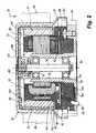
- Fig. 2 shows a preferred embodiment of the ECM 10 of Fig. 1, here in the form of an external rotor motor 10.
- This has a base portion 70 which is integrally formed with a bearing support tube 72 in which two ball bearings 74, 76 are located, which is a shaft Store 78, at the upper end of a rotor bell 80 is attached.
- a spring 82 creates a bias between the upper ball bearing 74 and the rotor bell 80, as well as between the inner rings of the two ball bearings.
- At the lower end of the shaft 78 is a snap ring 84.
- the base member 70 and the bearing support tube 72 may be made of a suitable plastic, or for example of die-cast aluminum with a magnesium content below 6%.
- the rotor bell 80 like the base part 70, preferably consists of a suitable plastic with embedded carbon fibers in order to prevent static charging of the surface of the plastic.
- the surface resistance is preferably below 10 9 ⁇ , more preferably in the range of about 10 5 to about 10 9 ⁇ .
- a plastic is used which is resistant to short-term flame exposure.
- the rotor bell 80 carries on its outside fan blades 86, with which it is integrally formed. Downwards it widens conically to a so-called skirt 88, which cooperates with a stationary part 89 which - as shown - protrudes into these contactors 88 and thus prevents foreign bodies from entering the interior of the electric motor 10.
- the flow direction of the air is designated 91, ie from top to bottom, so that in the region of the opening 87 of the skirt 88 a suction effect is created, which counteracts the penetration of foreign bodies.
- a cup-shaped part 90 made of a soft ferromagnetic material is fixed by means of plastic rivets 92, and on the inside of the part 90 of the rotor magnet 14 is fixed, preferably a so-called rubber magnet, which consists of a mixture of rubbery substances and suitable Hartferriten. This has opposite a hard permanent magnet the advantage that when friction between the stator 100 and rotor magnet 14 no friction sparks can occur.
- stator of the electric motor 10 In the radial space between the rotor magnet 14 and the bearing support tube 72 is the stator of the electric motor 10 with a laminated stator core 100, which is pressed onto the outside of the bearing support tube 72, a two-part bobbin 102, 104, and the stator winding 12.
- the embodiment shows a single-stranded ECM 10 with a single winding 12. This is operated in a two-pulse manner, see, for example, the DE 23 46 380 where a corresponding electric motor is described.
- the invention is of course equally suitable for motors with more than one strand and with more than two current pulses per rotor rotation of 360 ° el.
- the printed circuit board 16 with the Hall IC 18 is below the laminated stator core 100 and the stator winding 12 below the printed circuit board 16 with the Hall IC 18.
- the potting compound 110 has a thickness of at least 3 mm.
- the potting compound 110 serves not only for the insulation of the winding 12 and the electronics, but also for dissipating electrostatic charge. For this reason, it is weakly conductive. Their surface resistance is preferably in the range of 10 5 to 10 9 ⁇ . In practice, values of 3 ⁇ may occasionally occur. The surface resistance must not be too low, so that no disturbing currents flow from the winding 12 to the Hall IC 18, which could disturb the Hall signal. Optimal is a resistance gradient in the sense that the resistivity of the insulation at the surface is lower than in the interior of the insulation.
- the winding 12 is connected via connections 114 on the printed circuit board 16 to the lines 46, 48, which lead to the commutation 34.
- the potting material 110 preferably also extends through the air gap 120 of the electric motor 10 and completely covers the air gap side of the stator lamination packet 100, cf. the US 5,973,424 ,
- ECM 10 an intrinsically safe ECM 10
- the commutation electronics 34 of which is preferably arranged outside the electric motor 10 and need not be intrinsically safe, because a strict electrical isolation 60 is provided between it and the sensor electronics located in the ECM 10 (on the printed circuit board 16).
- the printed circuit board 32 can be arranged in a conventional manner in an explosion-proof housing outside of the ECM 10.
- a preferred application of such ECM 10 is a so-called tube fan, so a fan that is installed in the pipe of a ventilation system in which explosive media can occur.
- an isolating transformer (analogous to the transformer 52) can also be provided between the network 40 and the rectifier 44 at locations A, B (FIG. 1), which isolates the commutation electronics 34 galvanically from the network 40.
- a lower intermediate circuit voltage between the lines 45, 47 is then possible, e.g. 20 V.
- many other modifications and modifications are possible without departing from the scope of the invention.
Landscapes
- Engineering & Computer Science (AREA)
- Power Engineering (AREA)
- Mechanical Engineering (AREA)
- General Engineering & Computer Science (AREA)
- Brushless Motors (AREA)
- Permanent Magnet Type Synchronous Machine (AREA)
Description
- Die Erfindung betrifft eine Motoranordnung mit einem elektronisch kommutierten Elektromotor in explosionsgeschützter Ausführung, wie er z.B. zum Antrieb von Lüftern in einer potenziell explosiven Atmosphäre Verwendung finden kann.
- Bei derartigen Motoranordnungen werden gewöhnlich sogenannte Sicherheitsbarrieren verwendet, die jedoch für viele Anwendungsfälle zu teuer sind. Auch können bei solchen Sicherheitsbarrieren zu hohe Spannungsabfälle auftreten.
- Die
US-A-6 008 602 undWO-A-9 748 178 - Es ist eine Aufgabe der Erfindung, eine neue Motoranordnung bereitzustellen, deren Motor sich für den Betrieb in einer explosionsgefährdeten Umgebung eignet.
- Nach der Erfindung wird diese Aufgabe gelöst durch den Gegenstand des Anspruchs 1. Bei einer erfindungsgemäßen Motoranordnung verwendet man also einen Elektromotor mit galvanomagnetischem Sensor. Zwischen Motorstromkreis und Sensorstromkreis ist eine vollständige galvanische Trennung vorgesehen, wodurch mit Sicherheit verhindert wird, dass im Fehlerfall energiereiche Netzspannung in den Sensorstromkreis gelangt. Die eigentliche Kommutierungselektronik der Motoranordnung ist bevorzugt außerhalb des Elektromotors angeordnet. Dadurch wird es möglich, z.B. auf einer im Elektromotor eingebauten, relativ kleinen Leiterplatte den Sensorstromkreis elektrisch vollständig vom Wicklungsstromkreis des Elektromotors zu trennen. Da das Ausgangssignal des Sensors über einen Optokoppler der Kommutierungselektronik zugeführt wird, ist auch hier eine vollständige galvanische Trennung gegeben.
- Weitere Einzelheiten und vorteilhafte Weiterbildungen der Erfindung ergeben sich aus dem im folgenden beschriebenen und in der Zeichnung dargestellten, in keiner Weise als Einschränkung der Erfindung zu verstehenden Ausführungsbeispiel, sowie aus den Unteransprüchen. Es zeigt:
- Fig. 1
- eine Schemadarstellung einer bevorzugten Ausführungsform der Erfindung, und
- Fig. 2
- eine bevorzugte Ausführungsform eines Elektromotors zur Verwendung bei der Anordnung gemäß Fig. 1.
- In der nachfolgenden Beschreibung werden gleiche oder gleich wirkende Teile mit denselben Bezugszeichen bezeichnet und gewöhnlich nur einmal beschrieben.
- Fig. 1 zeigt in schematisierter Form ein Ausführungsbeispiel einer erfindungsgemäßen Motoranordnung 11. Rechts befindet sich ein elektronisch kommutierter Elektromotor (ECM) 10 mit einer Statorwicklung 12, einem permanentmagnetischen Rotor 14, und einer im ECM 10 isoliert angeordneten Leiterplatte 16, auf welcher ein Hall-IC 18 angeordnet ist, der von einem Magnetfeld des Rotors 14 gesteuert wird. Die Teile 12, 14, 16, 18, 20 sind nur ganz schematisch angedeutet, um das Verständnis der Erfindung zu erleichtern. Z.B. werden in der Praxis meist vier- oder sechspolige Rotoren 14 verwendet.
- Die Leiterplatte 16 trägt auch einen Optokoppler 20, eine Schmelzsicherung 21, einen Widerstand 22, zwei Zenerdioden 23, und einen Widerstand 24. Sie erhält eine Gleichspannung von 10 V über zwei Leitungen 26, 28 von einem Gleichrichter 30, der auf einer externen Leiterplatte 32 angeordnet ist, auf der sich auch die Kommutierungselektronik 34 befindet, an welche die Wicklung 12 angeschlossen ist. Diese Leiterplatte 32 befindet sich bevorzugt außerhalb des ECM 10, gewöhnlich in einem explosionsgeschützten Gehäuse (druckfeste Kapselung). Die Kommutierungselektronik 34 enthält bevorzugt eine elektronische Begrenzung des Motorstroms, wie sie z.B. aus der
EP-A2-0739084 bekannt ist. Die Minusleitung 28 ist aus Gründen der Redundanz doppelt ausgeführt. - Die Leiterplatte 32 wird im Betrieb über Anschlüsse 36, 38 an eine Wechselspannungsquelle 40 angeschlossen, typisch an ein Wechselstromnetz mit 230 V, 50 Hz, oder an ein Drehstromnetz. Diese Wechselspannung wird über einen Gleichrichter 44 (mit Glättungselektronik, also Kondensatoren etc.) gleichgerichtet und über einen Gleichstrom-Zwischenkreis 45, 47 der Kommutierungselektronik 34 zugeführt. Die Spannung am Gleichstrom-Zwischenkreis 45, 47 kann je nach Motortyp z.B. zwischen 20 V und mehr als 350 V liegen.
- Die Signale vom Ausgang des Optokopplers 20 werden über zwei Leitungen 46, 48 der Kommutierungselektronik 34 zugeführt und steuern in üblicher Weise die Kommutierung abhängig von der Stellung des Rotors 14.
- An die Anschlüsse 36, 38 ist auch die Primärwicklung 50 eines kurzschlussfesten Trenntransformators 52 (bevorzugt entsprechend EN50020, Abschnitt 8.1) angeschlossen, an dessen Sekundärwicklung 54 der Gleichrichter 30 angeschlossen ist, der den Hall-IC 18 und den Optokoppler 20 speist.
- Die positive Leitung 26 ist über die Schmelzsicherung 21 (z.B. 62 mA, 125 V) und einen Knotenpunkt 25 mit der Anode der LED 58 des Optokopplers 20 verbunden, deren Katode über einen Widerstand 22 mit dem Signalausgang des Hall-IC 18 verbunden ist. Ferner ist der Knotenpunkt 25 über den Widerstand 24 mit dem Stromversorgungseingang des Hall-IC 18 verbunden. Die negative Leitung 28 ist mit dem Minusanschluss des Hall-IC 18 verbunden. Zwischen dem Knotenpunkt 25 und der negativen Leitung 28 liegen die beiden Zenerdioden 23, z.B. für 5,6 V. Damit wird sicher gestellt, dass die Spannung im eigensicheren Kreis nicht > 5,6 V werden kann. Im Fehlerfall löst die Schmelzsicherung 21 aus. Der Vorwiderstand für die Zenerdioden 23 befindet sich, am Ausgang des Gleichrichters 30, auf der externen Leiterplatte 32.
- Die Widerstände 22 und 24 (z.B. jeweils 1 kΩ) sind so dimensioniert, dass bei einem Kurzschluss die maximale an ihnen erzeugte elektrische Leistung deutlich unter zwei Dritteln der maximal zulässigen Verlustleistung dieser Widerstände liegt.
- Mit 60 ist symbolisch die galvanische Trennung zwischen eigensicherem Sensorstromkreis (unterhalb der Linie 60) und energiereichem Motorstromkreis (oberhalb der Trennlinie 60) angedeutet. Diese Trennung wird gebildet durch den Trenntransformator 52, den Optokoppler 20, und teilweise auch durch eine Isolation 62, welche im Luftspalt 63 zwischen dem Hall-IC 18 und dem Rotor 14 angeordnet ist. Die Isolation 62 ist in Fig. 1 nur symbolisch angedeutet. Sie ist in Fig. 2 an einem bevorzugten Beispiel dargestellt. Bevorzugt wird sie am Stator vorgesehen, doch ist es auch nicht ausgeschlossen, eine entsprechende Isolation am Rotor 14 vorzusehen.
- Erläuternd wird hierzu auf folgendes hingewiesen: Für eigensichere Elektromotoren sind durch die Norm relativ große Isolationsdicken vorgeschrieben, die bei kleineren Motoren, und speziell bei elektronisch kommutierten Motoren, nicht eingehalten werden können, weil sonst der Motor nicht funktionsfähig wäre. Z.B. müsste nach der Norm eine Isolationsschicht an der Stelle 63 eine Dicke von mindestens 3 mm haben, aber in diesem Fall könnte der Hall-IC 18 nicht mehr durch das Magnetfeld des Rotors 14 gesteuert werden.
- Durch den Trenntransformator 52 und den Optokoppler 20 wird jedoch eine komplette galvanische Trennung der Leiterplatte 16 vom Netz 40 erreicht, so dass Eigensicherheit auch gegeben ist, wenn die Isolation 62 nicht die an sich vorgeschriebene Dicke hat. Man erkennt ohne weiteres, dass selbst eine weniger dicke Isolationsschicht 62 in diesem Fall zusätzlich zur Eigensicherheit beiträgt.
- Fig. 2 zeigt eine bevorzugte Ausführungsform des ECM 10 der Fig. 1, hier in Form eines Außenläufermotors 10. Dieser hat ein Basisteil 70, das einstückig mit einem Lagertragrohr 72 ausgebildet ist, in dem sich zwei Kugellager 74, 76 befinden, welche eine Welle 78 lagern, an deren oberem Ende eine Rotorglocke 80 befestigt ist. Eine Feder 82 erzeugt eine Vorspannung zwischen dem oberen Kugellager 74 und der Rotorglocke 80, sowie zwischen den Innenringen der beiden Kugellager. Am unteren Ende der Welle 78 befindet sich ein Sprengring 84. Das Basisteil 70 und das Lagertragrohr 72 können aus einem geeigneten Kunststoff hergestellt sein, oder z.B. aus Aluminium-Druckguss mit einem Magnesiumgehalt unter 6 %.
- Die Rotorglocke 80 besteht, ebenso wie das Basisteil 70, bevorzugt aus einem geeigneten Kunststoff mit eingelagerten Kohlefasern, um eine statische Aufladung der Oberfläche des Kunststoffs zu verhindern. Der Oberflächenwiderstand liegt bevorzugt unter 109 Ω, besonders bevorzugt im Bereich von etwa 105 bis etwa 109 Ω. Bevorzugt wird ein Kunststoff verwendet, der beständig gegen kurzzeitige Flammeinwirkung ist.
- Die Rotorglocke 80 trägt auf ihrer Außenseite Lüfterflügel 86, mit denen sie einstückig ausgebildet ist. Nach unten erweitert sie sich konisch zu einer sogenannten Schürze 88, die mit einem stationären Teil 89 zusammenwirkt, das - wie dargestellt - in diese Schütze 88 ragt und so verhindert, dass Fremdkörper in das Innere des Elektromotors 10 gelangen. Die Strömungsrichtung der Luft ist mit 91 bezeichnet, also von oben nach unten, so dass im Bereich der Öffnung 87 der Schürze 88 eine Sogwirkung entsteht, welche dem Eindringen von Fremdkörpern entgegenwirkt.
- Im Inneren der Rotorglocke 80 ist ein becherförmiges Teil 90 aus einem weichferromagnetischen Werkstoff mittels Kunststoffnieten 92 befestigt, und auf der Innenseite des Teils 90 ist der Rotormagnet 14 befestigt, bevorzugt ein sogenannter Gummimagnet, der aus einer Mischung von gummiartigen Substanzen und geeigneten Hartferriten besteht. Dies hat gegenüber einem harten Dauermagneten den Vorteil, dass bei Reibung zwischen Stator 100 und Rotormagnet 14 keine Reibungsfunken entstehen können.
- In dem radialen Raum zwischen dem Rotormagneten 14 und dem Lagertragrohr 72 befindet sich der Stator des Elektromotors 10 mit einem Statorblechpaket 100, das auf die Außenseite des Lagertragrohrs 72 aufgepresst ist, einem zweiteiligen Wickelkörper 102, 104, und der Statorwicklung 12. (Das Ausführungsbeispiel zeigt einen einsträngigen ECM 10 mit einer einzigen Wicklung 12. Diese wird zweipulsig betrieben, vgl. z.B. die
DE 23 46 380 , wo ein entsprechender Elektromotor beschrieben ist. Die Erfindung eignet sich naturgemäß in gleicher Weise für Motoren mit mehr als einem Strang und mit mehr als zwei Stromimpulsen pro Rotordrehung von 360° el.) - Unterhalb des Statorblechpakets 100 und der Statorwicklung 12 befindet sich die Leiterplatte 16 mit dem Hall-IC 18. Diese Leiterplatte 16 ist, ebenso wie das Statorblechpaket 100 und die Wicklung 12, komplett mit einer sehr schwach leitfähigen Vergussmasse 110 umspritzt, die bevorzugt auch den Hall-IC 18 vollständig umgibt, welch letzterer etwa gegenüber dem unteren Ende 112 des Rotormagneten 14 angeordnet ist, also in dessen Streuflussbereich. Im Bereich der Wicklung 12 und der sonstigen stromführenden Teile mit energiereichen Strömen hat die Vergussmasse 110 eine Dicke von mindestens 3 mm.
- Die Vergussmasse 110 dient nicht nur zur Isolierung der Wicklung 12 und der Elektronik, sondern auch zum Ableiten von elektrostatischer Aufladung. Aus diesem Grunde ist sie schwach leitend. Ihr Oberflächenwiderstand liegt bevorzugt im Bereich von 105 bis 109 Ω. In der Praxis können sich gelegentlich Werte von 3 Ω einstellen. Der Oberflächenwiderstand darf nicht zu niedrig sein, damit keine störenden Ströme von der Wicklung 12 zum Hall-IC 18 fließen, was das Hallsignal stören könnte. Optimal ist ein Widerstandsgradient in dem Sinne, dass der spezifische Widerstand der Isolation an der Oberfläche niedriger ist als im Inneren der Isolation.
- Auf diese Weise befindet sich auch zwischen dem Rotormagneten 14 und dem Hall-IC 18 die bei Fig. 1 beschriebene, schwach leitende Isolierschicht 62, welche für eine gute galvanische Trennung 60 zwischen ECM 10 und Sensorstromkreis und damit für die sogenannte Eigensicherheit des Elektromotors 10 von großem Vorteil ist.
- Bezüglich der Einzelheiten des Umspritzens des Stators mit einem Kunststoff wird der Kürze halber verwiesen auf die
US 5 973 424 (US-1014 ), wo ein geeignetes Verfahren und geeignete Werkstoffe ausführlich beschrieben sind. - Die Wicklung 12 ist über Anschlüsse 114 auf der Leiterplatte 16 mit den Leitungen 46, 48 verbunden, welche zur Kommutierungselektronik 34 führen.
- Das Vergussmaterial 110 erstreckt sich bevorzugt auch durch den Luftspalt 120 des Elektromotors 10 und bedeckt die Luftspaltseite des Statorblechpakets 100 vollständig, vgl. die
US 5 973 424 . - Man erhält so einen eigensicheren ECM 10, dessen Kommutierungselektronik 34 bevorzugt außerhalb des Elektromotors 10 angeordnet ist und nicht eigensicher zu sein braucht, weil zwischen ihr und der im ECM 10 befindlichen Sensorelektronik (auf der Leiterplatte 16) eine strikte galvanische Trennung 60 vorgesehen ist. Die Leiterplatte 32 kann in üblicher Weise in einem explosionsgeschützten Gehäuse außerhalb des ECM 10 angeordnet werden. Eine bevorzugte Anwendung eines solchen ECM 10 ist ein sogenannter Rohrlüfter, also ein Lüfter, der in das Rohr einer Belüftungsanlage eingebaut wird, in der auch explosive Medien vorkommen können.
- Bei Bedarf kann auch zwischen dem Netz 40 und dem Gleichrichter 44 an den Stellen A, B (Fig. 1) ein Trenntransformator (analog dem Transformator 52) vorgesehen werden, welcher die Kommutierungselektronik 34 galvanisch vom Netz 40 trennt. Dadurch ist dann auch eine niedrigere Zwischenkreisspannung zwischen den Leitungen 45, 47 möglich, z.B. 20 V. Auch sonst sind vielfache Abwandlungen und Modifikationen möglich, ohne den Rahmen der Erfindung zu verlassen.
Claims (19)
- Motoranordnung (11) mit einem elektronisch kommutierten Elektromotor (10) in explosionsgeschützter Ausführung, der einen permanentmagnetischen Rotor (14) und einen Stator (100) aufweist,
mit folgenden Merkmalen:Am Stator des Elektromotors (10), und vom permanentmagnetischen Rotor (14) durch einen Luftspalt (63) getrennt, ist zur Erfassung eines Magnetfelds vom permanentmagnetischen Rotor (14) mindestens ein galvanomagnetischer Rotorstellungssensor (18) vorgesehen, dessen Ausgangssignal zur Steuerung einer Kommutierungselektronik (34) dient;die Stromversorgung des galvanomagnetischen Rotorstellungssensors (18) erfolgt aus einem Wechsel- oder Drehstromnetz (40) unter Zwischenschaltung eines Trenntransformators (52);das Ausgangssignal des galvanomagnetischen Sensors (18) wird über einen Optokoppler (20) der Kommutierungselektronik (34) zugeführt. - Motoranordnung nach Anspruch 1, bei welcher der Trenntransformator (52) in eigensicherer Ausführung ausgebildet ist.
- Motoranordnung nach Anspruch 1 oder 2, bei welcher der galvanomagnetische Rotorstellungssensor (18) als Hall-IC ausgebildet ist.
- Motoranordnung nach einem der vorhergehenden Ansprüche, bei welcher der galvanomagnetische Rotorstellungssensor (18) auf einer Leiterplatte (16) angeordnet ist, welche von einer schwach leitenden Vergussmasse (62, 110) umgeben ist, die bevorzugt auch den galvanomagnetischen Sensor (18) umgibt.
- Motoranordnung nach Anspruch 4, bei welcher sich die schwach leitende Vergussmasse (62) auch in den Luftspalt (63) zwischen permanentmagnetischem Rotor (14) und Rotorstellungssensor (18) erstreckt.
- Motoranordnung nach einem der vorhergehenden Ansprüche, bei welcher das Statorblechpaket (100) und die Statorwicklung (12) von einer schwach leitenden Vergussmasse (110) umgeben sind.
- Motoranordnung nach einem der Ansprüche 4 bis 6, bei welcher die Vergussmasse einen Oberflächenwiderstand aufweist, der im Bereich von etwa 109 Ω oder darunter liegt.
- Motoranordnung nach einem der vorhergehenden Ansprüche, deren Elektromotor (10) als Außenläufermotor (10) ausgebildet ist, dessen Rotorglocke (80) im Bereich ihres freien Endes eine radiale Erweiterung (88) aufweist.
- Motoranordnung nach Anspruch 8, bei welcher auf der Außenseite der Rotorglocke (80) Lüfterflügel (86) angeordnet sind.
- Motoranordnung nach Anspruch 8 und 9, bei welcher die radiale Erweiterung (88) der Rotorglocke (80) auf der Abströmseite der von den Lüfterflügeln (86) geförderten Luft (91) vorgesehen ist.
- Motoranordnung nach Anspruch 9 oder 10, bei welcher die Rotorglocke (80) aus Kunststoff ausgebildet ist und Lüfterflügel (86) einstückig mit ihr ausgebildet sind.
- Motoranordnung nach einem der Ansprüche 8 bis 11, bei welcher innerhalb einer Rotorglocke (80) aus Kunststoff ein weichferromagnetisches Rückschlussteil (90) befestigt ist, welches als Träger und magnetischer Rückschluss (yoke) für einen Permanentmagneten (14) des Rotors dient.
- Motoranordnung nach Anspruch 11 oder 12, bei welcher der Kunststoff der Rotorglocke (80) schwach leitend ausgebildet ist und einen Oberflächenwiderstand von kleiner als 109 Ω hat.
- Motoranordnung nach Anspruch 13, bei welcher dem Kunststoff der Rotorglocke (80) zwecks Herabsetzung seines Oberflächenwiderstands Kohlefasern zugesetzt sind.
- Motoranordnung nach einem der Ansprüche 9 bis 14, bei welcher der vom Elektromotor (10) angetriebene Lüfter (86) als sogenannter Rohrlüfter ausgebildet ist, welcher zur Anordnung in einem von einem Gas durchströmten Rohr ausgebildet ist.
- Motoranordnung nach einem der vorhergehenden Ansprüche, bei welcher eine Strombegrenzung (34) für den zur Motorwicklung (12) fließenden Strom vorgesehen ist.
- Motoranordnung nach einem der vorhergehenden Ansprüche, bei welcher die Kommutierungselektronik (34) der Motoranordnung (11) mindestens teilweise außerhalb des Elektromotors (10) angeordnet ist.
- Motoranordnung nach Anspruch 17, bei welcher die Kommutierungselektronik (34) in einem druckfesten Gehäuse außerhalb des Elektromotors (10) explosionsgeschützt angeordnet ist.
- Motoranordnung nach einem der vorhergehenden Ansprüche, bei welcher der Rotormagnet (14) als Gummimagnet ausgebildet ist.
Applications Claiming Priority (2)
| Application Number | Priority Date | Filing Date | Title |
|---|---|---|---|
| DE20009553 | 2000-05-27 | ||
| DE20009553U | 2000-05-27 |
Publications (2)
| Publication Number | Publication Date |
|---|---|
| EP1160960A1 EP1160960A1 (de) | 2001-12-05 |
| EP1160960B1 true EP1160960B1 (de) | 2007-11-21 |
Family
ID=7942115
Family Applications (1)
| Application Number | Title | Priority Date | Filing Date |
|---|---|---|---|
| EP01107240A Expired - Lifetime EP1160960B1 (de) | 2000-05-27 | 2001-03-23 | Explosionsgeschützte Motoranordnung |
Country Status (5)
| Country | Link |
|---|---|
| US (1) | US6501200B2 (de) |
| EP (1) | EP1160960B1 (de) |
| JP (1) | JP2002034208A (de) |
| CA (1) | CA2348662C (de) |
| DE (2) | DE20105050U1 (de) |
Cited By (1)
| Publication number | Priority date | Publication date | Assignee | Title |
|---|---|---|---|---|
| DE202011002408U1 (de) | 2011-02-04 | 2012-05-07 | Ebm-Papst Mulfingen Gmbh & Co. Kg | Gleichstrom-Elektromotor in explosionsgeschützter Bauart |
Families Citing this family (24)
| Publication number | Priority date | Publication date | Assignee | Title |
|---|---|---|---|---|
| JP4716065B2 (ja) * | 2000-06-21 | 2011-07-06 | ミネベア株式会社 | 軸流送風機 |
| DE10164204A1 (de) * | 2001-12-27 | 2003-07-17 | Siemens Linear Motor Systems G | Schutzeinrichtung für Elektromotor mit Sensor und Auswerteeinheit |
| CN2699018Y (zh) * | 2004-02-02 | 2005-05-11 | 鸿富锦精密工业(深圳)有限公司 | 风扇马达 |
| CN2695687Y (zh) * | 2004-04-17 | 2005-04-27 | 鸿富锦精密工业(深圳)有限公司 | 改良风扇装置 |
| US7061155B1 (en) * | 2005-01-04 | 2006-06-13 | Asia Vital Component Co., Ltd. | Rotor device capable of dissipating heat and resisting foreign objects |
| DE202005003413U1 (de) * | 2005-02-24 | 2006-07-13 | Ebm-Papst St. Georgen Gmbh & Co. Kg | Minilüfter |
| TWI314184B (en) * | 2005-03-18 | 2009-09-01 | Delta Electronics Inc | Fan case |
| CN100453819C (zh) * | 2005-03-18 | 2009-01-21 | 台达电子工业股份有限公司 | 风扇壳体 |
| US20070077783A1 (en) * | 2005-09-30 | 2007-04-05 | Trw Automotive U.S. Llc | Rotary connector system |
| US20070252487A1 (en) * | 2006-04-28 | 2007-11-01 | Nidec Corporation | Motor and pump having magnetic sensor, connecting method between circuit board having magnetic sensor and stator, and manufacturing method of motor and pump |
| US7898786B2 (en) * | 2007-01-26 | 2011-03-01 | Siemens Industry, Inc. | Intrinsically safe galvanically isolated barrier device and method thereof |
| EP2093867A1 (de) * | 2008-02-25 | 2009-08-26 | ebm-papst Mulfingen GmbH & Co.KG | Statorkondensator |
| DE102008045139A1 (de) | 2008-09-01 | 2010-03-04 | Endress + Hauser Flowtec Ag | Opto-elektronische Vorrichtung mit einer eingebauten Sicherungsvorrichtung |
| JP2013187922A (ja) * | 2012-03-06 | 2013-09-19 | Nippon Densan Corp | ファンモータ |
| ITTO20120832A1 (it) * | 2012-09-26 | 2014-03-27 | Elcis Encoder S R L | Trasduttore magnetico antideflagrante |
| DE102012112501A1 (de) * | 2012-12-18 | 2014-06-18 | Elodrive Gmbh | Elektromotor |
| DE102013105419B3 (de) * | 2013-05-27 | 2014-07-17 | Ebm-Papst Mulfingen Gmbh & Co. Kg | EC-Motor mit dynamischer Bestimmung der Degradation der Optokoppler |
| JP6221549B2 (ja) * | 2013-09-19 | 2017-11-01 | 村田機械株式会社 | 接触検出部を備える磁気装置及び磁気装置のための接触検出方法 |
| CN105201875B (zh) * | 2015-09-28 | 2018-03-09 | 无锡市南方防爆电机有限公司 | 一种防爆风机结构 |
| EP3378010A4 (de) * | 2015-11-16 | 2020-07-22 | Aegex Technologies, LLC | Eigensichere mobile vorrichtung |
| CN112018964B (zh) * | 2016-03-09 | 2023-05-23 | 株式会社电装 | 电动机及电动机的制造方法 |
| DE102017003865B4 (de) * | 2017-04-21 | 2025-12-18 | Lenze Se (Societas Europaea) | Elektrische Maschine |
| US11690495B2 (en) * | 2018-06-06 | 2023-07-04 | Intuitive Surgical Operations, Inc. | Systems and methods for high-speed data transmission across an electrical isolation barrier |
| FR3117412A1 (fr) * | 2020-12-14 | 2022-06-17 | Valeo Systemes Thermiques | Système de ventilation d’un véhicule automobile |
Family Cites Families (20)
| Publication number | Priority date | Publication date | Assignee | Title |
|---|---|---|---|---|
| US3383574A (en) * | 1964-06-30 | 1968-05-14 | Gen Electric | Brushless direct current motor and torquer |
| DE2659233C3 (de) | 1976-12-28 | 1979-07-19 | Siemens Ag, 1000 Berlin Und 8000 Muenchen | Kollektorloser Gleichstrommotor |
| JPS5931290B2 (ja) * | 1978-12-08 | 1984-08-01 | 株式会社帝国電機製作所 | キヤンドモ−タの運転監視装置 |
| US4484127A (en) | 1982-05-28 | 1984-11-20 | Otis Elevator Company | Inverter power transistor protection |
| DE3614748C2 (de) | 1985-04-30 | 1995-12-14 | Papst Motoren Gmbh & Co Kg | Elektromotor, insbesondere kollektorloser Gleichstrommotor, mit einem Außenrotor |
| JPH0442559Y2 (de) * | 1985-10-03 | 1992-10-07 | ||
| EP0259724B1 (de) * | 1986-09-12 | 1990-11-22 | Siemens Aktiengesellschaft | Leiterplatte |
| US4827196A (en) * | 1987-12-03 | 1989-05-02 | E. I. Du Pont De Nemours And Company | Motor control arrangement |
| DE3825035B4 (de) * | 1988-07-09 | 2006-11-23 | Flux-Geräte GmbH | Bürstenloser, elektrisch kommutierter Motor für eine Faß- oder eine Behälterpumpe zum Betieb an einem Wechselspannungsnetz |
| US5220258A (en) * | 1990-06-18 | 1993-06-15 | Papst-Motoren Gmbh & Co. Kg | Drive circuit for a brushless direct-current motor |
| DE4019338A1 (de) * | 1990-06-18 | 1991-12-19 | Papst Motoren Gmbh & Co Kg | Treiberschaltung fuer einen buerstenlosen gleichstrommotor |
| US5473229A (en) * | 1992-05-27 | 1995-12-05 | General Electric Company | Interface between programmable electronically commutated motor and personal computer and method of operation |
| EP0643473B1 (de) * | 1993-09-15 | 1998-04-29 | PAPST-MOTOREN GmbH & Co. KG | Anordnung mit einem über eine Halbleiteranordnung kommutierten kollektorlosen Gleichstrommotor |
| JPH07115787A (ja) * | 1993-10-18 | 1995-05-02 | Matsushita Electric Ind Co Ltd | ブラシレスモータ |
| US5539601A (en) * | 1994-05-12 | 1996-07-23 | Siemens Energy & Automation, Inc. | Apparatus and method for thermal protection of electric motors |
| EP0739084B1 (de) | 1995-04-22 | 2002-07-24 | PAPST-MOTOREN GmbH & Co. KG | Verfahren zum Steuern oder Regeln eines Elektromotors, und Anordnung zur Durchführung eines solchen Verfahrens |
| US5821706A (en) * | 1995-09-28 | 1998-10-13 | Mitsubishi Jidosha Kogyo Kabushiki Kaisha | Control apparatus and method for initiating power generation for hybrid electric automobile |
| GB9521332D0 (en) | 1995-10-18 | 1995-12-20 | Switched Reluctance Drives Ltd | Current control circuit for a reluctance machine |
| ATE208099T1 (de) * | 1996-06-07 | 2001-11-15 | Papst Motoren Gmbh & Co Kg | Anordnung mit einem elektronisch kommutierten motor |
| EP0903007B1 (de) * | 1996-06-07 | 2001-10-31 | Papst-Motoren Gmbh & Co. Kg | Anordnung mit einem elektronisch kommutierten motor |
-
2001
- 2001-03-22 DE DE20105050U patent/DE20105050U1/de not_active Expired - Lifetime
- 2001-03-23 DE DE50113281T patent/DE50113281D1/de not_active Expired - Lifetime
- 2001-03-23 EP EP01107240A patent/EP1160960B1/de not_active Expired - Lifetime
- 2001-05-16 US US09/859,571 patent/US6501200B2/en not_active Expired - Fee Related
- 2001-05-24 CA CA002348662A patent/CA2348662C/en not_active Expired - Fee Related
- 2001-05-28 JP JP2001159569A patent/JP2002034208A/ja not_active Ceased
Cited By (2)
| Publication number | Priority date | Publication date | Assignee | Title |
|---|---|---|---|---|
| DE202011002408U1 (de) | 2011-02-04 | 2012-05-07 | Ebm-Papst Mulfingen Gmbh & Co. Kg | Gleichstrom-Elektromotor in explosionsgeschützter Bauart |
| WO2012103983A2 (de) | 2011-02-04 | 2012-08-09 | Ebm-Papst Mulfingen Gmbh & Co. Kg | Gleichstrom-elektromotor in explosionsgeschützter bauart |
Also Published As
| Publication number | Publication date |
|---|---|
| EP1160960A1 (de) | 2001-12-05 |
| DE50113281D1 (de) | 2008-01-03 |
| US6501200B2 (en) | 2002-12-31 |
| JP2002034208A (ja) | 2002-01-31 |
| US20010048254A1 (en) | 2001-12-06 |
| CA2348662A1 (en) | 2001-11-27 |
| CA2348662C (en) | 2005-06-07 |
| DE20105050U1 (de) | 2001-06-28 |
Similar Documents
| Publication | Publication Date | Title |
|---|---|---|
| EP1160960A1 (de) | Explosionsgeschützte Motoranordnung | |
| EP3411940B1 (de) | Elektromotor für eine fluidpumpe, modulare motorfamilie zur bildung unterschiedlicher fluidpumpen mit mehreren solcher elektromotoren und herstellungsverfahren | |
| DE3825035B4 (de) | Bürstenloser, elektrisch kommutierter Motor für eine Faß- oder eine Behälterpumpe zum Betieb an einem Wechselspannungsnetz | |
| EP1422809B1 (de) | Elektromotor für einen Pumpenantrieb | |
| DE19811543A1 (de) | Bürstenloser Motor | |
| DE102017214776A1 (de) | Verfahren zum Fertigen eines Rotors für eine elektrische Maschine mit berührungslosem Leistungsübertragungssystem sowie Rotor, elektrische Maschine und Kraftfahrzeug | |
| DE2146893B2 (de) | Kollektorloser gleichstrommotor mit einer durch hallgeneratoren gesteuerten, aus halbleiterschaltelementen aufgebauten kommutierungseinrichtung | |
| DE19800234B4 (de) | Bürstenloser Motor | |
| DE2800886A1 (de) | Gleichstrommotor | |
| DE4303480A1 (de) | Elektromotor, insbesondere ein umrichtergespeister Asynchronmotor zum Antrieb von Kraftfahrzeugen | |
| DE102018202895A1 (de) | Basiseinheit, Motor und Luftblasvorrichtung | |
| DE102018202893A1 (de) | Basiseinheit, Motor und Luftblasvorrichtung | |
| DE19637192C2 (de) | Elektromotor, insbesondere Außenläufermotor, mit integrierter, an die Ständerwicklung angeschlossener Elektronikeinheit | |
| DE10355076B4 (de) | Elektromotor mit Sensor zur Erfassung der Rotorlage | |
| DE29901967U1 (de) | Elektromotor mit einer Anordnung zur Drehzahlüberwachung | |
| DE29802297U1 (de) | Bürstenloser Gleichstrommotor | |
| DE10307330B4 (de) | Filtergebläse für Atemschutzmasken oder -hauben | |
| DE102014103607A1 (de) | Redundantes bürstenloses Antriebssystem | |
| DE4419780A1 (de) | Ringförmiger Stator für elektrodynamische Drehmaschine | |
| DE102020203272A1 (de) | Motor | |
| EP3477829B1 (de) | Radiallüfter mit einem aussenläufermotor | |
| DE102023132281A1 (de) | Elektromotor-Anordnung | |
| DE10018626A1 (de) | Rotor-Kräfteausgleichsstruktur | |
| DE102017002865A1 (de) | Aufbau eines Axiallüfters | |
| DE3332533C2 (de) |
Legal Events
| Date | Code | Title | Description |
|---|---|---|---|
| PUAI | Public reference made under article 153(3) epc to a published international application that has entered the european phase |
Free format text: ORIGINAL CODE: 0009012 |
|
| AK | Designated contracting states |
Kind code of ref document: A1 Designated state(s): AT BE CH CY DE DK ES FI FR GB GR IE IT LI LU MC NL PT SE TR |
|
| AX | Request for extension of the european patent |
Free format text: AL;LT;LV;MK;RO;SI |
|
| 17P | Request for examination filed |
Effective date: 20011108 |
|
| AKX | Designation fees paid |
Free format text: AT BE CH CY DE DK ES FI FR GB GR IE IT LI LU MC NL PT SE TR |
|
| GRAP | Despatch of communication of intention to grant a patent |
Free format text: ORIGINAL CODE: EPIDOSNIGR1 |
|
| RAP1 | Party data changed (applicant data changed or rights of an application transferred) |
Owner name: EBM-PAPST ST. GEORGEN GMBH & CO. KG |
|
| GRAS | Grant fee paid |
Free format text: ORIGINAL CODE: EPIDOSNIGR3 |
|
| GRAA | (expected) grant |
Free format text: ORIGINAL CODE: 0009210 |
|
| RIN1 | Information on inventor provided before grant (corrected) |
Inventor name: REICH, HARALD Inventor name: ENGEL, WOLFGANG Inventor name: KARWATH, ARNO |
|
| AK | Designated contracting states |
Kind code of ref document: B1 Designated state(s): AT BE CH CY DE DK ES FI FR GB GR IE IT LI LU MC NL PT SE TR |
|
| REG | Reference to a national code |
Ref country code: GB Ref legal event code: FG4D Free format text: NOT ENGLISH |
|
| REG | Reference to a national code |
Ref country code: IE Ref legal event code: FG4D Free format text: LANGUAGE OF EP DOCUMENT: GERMAN |
|
| REG | Reference to a national code |
Ref country code: CH Ref legal event code: EP |
|
| REF | Corresponds to: |
Ref document number: 50113281 Country of ref document: DE Date of ref document: 20080103 Kind code of ref document: P |
|
| GBT | Gb: translation of ep patent filed (gb section 77(6)(a)/1977) |
Effective date: 20071221 |
|
| PG25 | Lapsed in a contracting state [announced via postgrant information from national office to epo] |
Ref country code: NL Free format text: LAPSE BECAUSE OF FAILURE TO SUBMIT A TRANSLATION OF THE DESCRIPTION OR TO PAY THE FEE WITHIN THE PRESCRIBED TIME-LIMIT Effective date: 20071121 Ref country code: ES Free format text: LAPSE BECAUSE OF FAILURE TO SUBMIT A TRANSLATION OF THE DESCRIPTION OR TO PAY THE FEE WITHIN THE PRESCRIBED TIME-LIMIT Effective date: 20080304 Ref country code: SE Free format text: LAPSE BECAUSE OF FAILURE TO SUBMIT A TRANSLATION OF THE DESCRIPTION OR TO PAY THE FEE WITHIN THE PRESCRIBED TIME-LIMIT Effective date: 20080221 |
|
| NLV1 | Nl: lapsed or annulled due to failure to fulfill the requirements of art. 29p and 29m of the patents act | ||
| PG25 | Lapsed in a contracting state [announced via postgrant information from national office to epo] |
Ref country code: FI Free format text: LAPSE BECAUSE OF FAILURE TO SUBMIT A TRANSLATION OF THE DESCRIPTION OR TO PAY THE FEE WITHIN THE PRESCRIBED TIME-LIMIT Effective date: 20071121 |
|
| PG25 | Lapsed in a contracting state [announced via postgrant information from national office to epo] |
Ref country code: DK Free format text: LAPSE BECAUSE OF FAILURE TO SUBMIT A TRANSLATION OF THE DESCRIPTION OR TO PAY THE FEE WITHIN THE PRESCRIBED TIME-LIMIT Effective date: 20071121 |
|
| ET | Fr: translation filed | ||
| PLBE | No opposition filed within time limit |
Free format text: ORIGINAL CODE: 0009261 |
|
| STAA | Information on the status of an ep patent application or granted ep patent |
Free format text: STATUS: NO OPPOSITION FILED WITHIN TIME LIMIT |
|
| BERE | Be: lapsed |
Owner name: EBM-PAPST ST. GEORGEN G.M.B.H. & CO. KG Effective date: 20080331 |
|
| PG25 | Lapsed in a contracting state [announced via postgrant information from national office to epo] |
Ref country code: PT Free format text: LAPSE BECAUSE OF FAILURE TO SUBMIT A TRANSLATION OF THE DESCRIPTION OR TO PAY THE FEE WITHIN THE PRESCRIBED TIME-LIMIT Effective date: 20080421 |
|
| REG | Reference to a national code |
Ref country code: IE Ref legal event code: FD4D |
|
| 26N | No opposition filed |
Effective date: 20080822 |
|
| PG25 | Lapsed in a contracting state [announced via postgrant information from national office to epo] |
Ref country code: MC Free format text: LAPSE BECAUSE OF NON-PAYMENT OF DUE FEES Effective date: 20080331 Ref country code: IE Free format text: LAPSE BECAUSE OF FAILURE TO SUBMIT A TRANSLATION OF THE DESCRIPTION OR TO PAY THE FEE WITHIN THE PRESCRIBED TIME-LIMIT Effective date: 20071121 |
|
| REG | Reference to a national code |
Ref country code: CH Ref legal event code: PL |
|
| PG25 | Lapsed in a contracting state [announced via postgrant information from national office to epo] |
Ref country code: GR Free format text: LAPSE BECAUSE OF FAILURE TO SUBMIT A TRANSLATION OF THE DESCRIPTION OR TO PAY THE FEE WITHIN THE PRESCRIBED TIME-LIMIT Effective date: 20080222 Ref country code: LI Free format text: LAPSE BECAUSE OF NON-PAYMENT OF DUE FEES Effective date: 20080331 Ref country code: CH Free format text: LAPSE BECAUSE OF NON-PAYMENT OF DUE FEES Effective date: 20080331 |
|
| PG25 | Lapsed in a contracting state [announced via postgrant information from national office to epo] |
Ref country code: BE Free format text: LAPSE BECAUSE OF NON-PAYMENT OF DUE FEES Effective date: 20080331 |
|
| PG25 | Lapsed in a contracting state [announced via postgrant information from national office to epo] |
Ref country code: CY Free format text: LAPSE BECAUSE OF FAILURE TO SUBMIT A TRANSLATION OF THE DESCRIPTION OR TO PAY THE FEE WITHIN THE PRESCRIBED TIME-LIMIT Effective date: 20071121 |
|
| PG25 | Lapsed in a contracting state [announced via postgrant information from national office to epo] |
Ref country code: AT Free format text: LAPSE BECAUSE OF NON-PAYMENT OF DUE FEES Effective date: 20080323 |
|
| PGFP | Annual fee paid to national office [announced via postgrant information from national office to epo] |
Ref country code: FR Payment date: 20100222 Year of fee payment: 10 |
|
| PGFP | Annual fee paid to national office [announced via postgrant information from national office to epo] |
Ref country code: GB Payment date: 20100323 Year of fee payment: 10 |
|
| PG25 | Lapsed in a contracting state [announced via postgrant information from national office to epo] |
Ref country code: LU Free format text: LAPSE BECAUSE OF NON-PAYMENT OF DUE FEES Effective date: 20080323 |
|
| PG25 | Lapsed in a contracting state [announced via postgrant information from national office to epo] |
Ref country code: TR Free format text: LAPSE BECAUSE OF FAILURE TO SUBMIT A TRANSLATION OF THE DESCRIPTION OR TO PAY THE FEE WITHIN THE PRESCRIBED TIME-LIMIT Effective date: 20071121 |
|
| PGFP | Annual fee paid to national office [announced via postgrant information from national office to epo] |
Ref country code: DE Payment date: 20100301 Year of fee payment: 10 |
|
| PG25 | Lapsed in a contracting state [announced via postgrant information from national office to epo] |
Ref country code: IT Free format text: LAPSE BECAUSE OF NON-PAYMENT OF DUE FEES Effective date: 20080331 |
|
| GBPC | Gb: european patent ceased through non-payment of renewal fee |
Effective date: 20110323 |
|
| REG | Reference to a national code |
Ref country code: FR Ref legal event code: ST Effective date: 20111130 |
|
| PG25 | Lapsed in a contracting state [announced via postgrant information from national office to epo] |
Ref country code: DE Free format text: LAPSE BECAUSE OF NON-PAYMENT OF DUE FEES Effective date: 20111001 Ref country code: FR Free format text: LAPSE BECAUSE OF NON-PAYMENT OF DUE FEES Effective date: 20110331 |
|
| REG | Reference to a national code |
Ref country code: DE Ref legal event code: R119 Ref document number: 50113281 Country of ref document: DE Effective date: 20111001 |
|
| PG25 | Lapsed in a contracting state [announced via postgrant information from national office to epo] |
Ref country code: GB Free format text: LAPSE BECAUSE OF NON-PAYMENT OF DUE FEES Effective date: 20110323 |