EP1160581A1 - Verfahren zum Bestimmen der Einfallsrichtung von Schallwellen - Google Patents
Verfahren zum Bestimmen der Einfallsrichtung von Schallwellen Download PDFInfo
- Publication number
- EP1160581A1 EP1160581A1 EP01109902A EP01109902A EP1160581A1 EP 1160581 A1 EP1160581 A1 EP 1160581A1 EP 01109902 A EP01109902 A EP 01109902A EP 01109902 A EP01109902 A EP 01109902A EP 1160581 A1 EP1160581 A1 EP 1160581A1
- Authority
- EP
- European Patent Office
- Prior art keywords
- function
- group
- added
- addition
- root
- Prior art date
- Legal status (The legal status is an assumption and is not a legal conclusion. Google has not performed a legal analysis and makes no representation as to the accuracy of the status listed.)
- Granted
Links
Images


Classifications
-
- G—PHYSICS
- G01—MEASURING; TESTING
- G01S—RADIO DIRECTION-FINDING; RADIO NAVIGATION; DETERMINING DISTANCE OR VELOCITY BY USE OF RADIO WAVES; LOCATING OR PRESENCE-DETECTING BY USE OF THE REFLECTION OR RERADIATION OF RADIO WAVES; ANALOGOUS ARRANGEMENTS USING OTHER WAVES
- G01S3/00—Direction-finders for determining the direction from which infrasonic, sonic, ultrasonic or electromagnetic waves, or particle emission, not having a directional significance, are being received
- G01S3/80—Direction-finders for determining the direction from which infrasonic, sonic, ultrasonic or electromagnetic waves, or particle emission, not having a directional significance, are being received using ultrasonic, sonic or infrasonic waves
- G01S3/802—Systems for determining direction or deviation from predetermined direction
- G01S3/808—Systems for determining direction or deviation from predetermined direction using transducers spaced apart and measuring phase or time difference between signals therefrom, i.e. path-difference systems
- G01S3/8083—Systems for determining direction or deviation from predetermined direction using transducers spaced apart and measuring phase or time difference between signals therefrom, i.e. path-difference systems determining direction of source
-
- G—PHYSICS
- G01—MEASURING; TESTING
- G01S—RADIO DIRECTION-FINDING; RADIO NAVIGATION; DETERMINING DISTANCE OR VELOCITY BY USE OF RADIO WAVES; LOCATING OR PRESENCE-DETECTING BY USE OF THE REFLECTION OR RERADIATION OF RADIO WAVES; ANALOGOUS ARRANGEMENTS USING OTHER WAVES
- G01S3/00—Direction-finders for determining the direction from which infrasonic, sonic, ultrasonic or electromagnetic waves, or particle emission, not having a directional significance, are being received
- G01S3/80—Direction-finders for determining the direction from which infrasonic, sonic, ultrasonic or electromagnetic waves, or particle emission, not having a directional significance, are being received using ultrasonic, sonic or infrasonic waves
- G01S3/86—Direction-finders for determining the direction from which infrasonic, sonic, ultrasonic or electromagnetic waves, or particle emission, not having a directional significance, are being received using ultrasonic, sonic or infrasonic waves with means for eliminating undesired waves, e.g. disturbing noises
Definitions
- the invention relates to a method for determining the Direction of incidence of sound waves propagating in water the genus defined in the preamble of claim 1.
- the received signals from a so-called Linear antenna forming, equidistant side by side lined up electroacoustic transducers, clipped and with a sampling frequency that is greater than twice the maximum permitted signal frequency of the received signals scanned.
- the samples are a so-called Beamformer fed, which first the samples around different defined delay times delayed to then being able to add them in phase.
- the result of Beamforming is the directional characteristic of the linear antenna, with a main lobe, the main direction of which is the direction of incidence a sound wave received by the underwater antenna determined, and with side lobes or side lobes, through a Staggered amplitude of the time-delayed samples, the so-called Shading, e.g. by a Dolph Chebyshev weighting, be reduced.
- the receive signals of a group of arranged equidistant on a cylinder base electroacoustic transducers amplified by means of a Potential-controlled flip-flops clipped, i.e. in one episode converted by rectangular pulses, and into a shift register pushed with a pulse sequence of a clock frequency.
- the Clock frequency is determined by the so-called Shannon theorem.
- the Shift register consists of individual memory cells whose Minimum number of memory cells at a given clock frequency is determined by a maximum desired delay time. Each memory cell of the shift register has an output for tapping the delay time required (Memory cell number divided by clock frequency) delayed Rectangular pulses.
- the received signals in fed an amplitude detector, one of the amplitude of the received signals proportional value to its output supplies.
- the output values of the amplitude detector are shown with the delayed one taken at the output of the shift registers Rectangular pulses multiplied and then summed up in phase.
- the possibly filtered sum signal is the group signal of Polar pattern formed with the group of transducers becomes.
- Such a process of pattern formation or Linear beamforming has the disadvantage that it is weakly coherent Receive signals by setting a threshold at Clipping of the received signals can be suppressed while disruptive noise signals of greater amplitude are emphasized and deliver the group signal of the directional characteristic. Therefore weak sound sources are suppressed and therefore not detected, and the false alarm rate increased.
- the invention has for its object in a method of the type mentioned at the beginning with a low signal-to-noise ratio the direction formation with a more precise recording of the Improve direction of incidence of sound waves and that To increase the detection capacity of the antenna.
- the object of the invention is through the features in the claim 1 solved.
- the inventive method has the advantage that Use of a non-linear, monotonous function with Compression of the range of values on the individual received signals whose level increased more in the area of the zero crossing and thus weak signals are emphasized more.
- a threshold dependent on the useful / interference ratio for detecting the Zero crossing of the signal is not required.
- the through the Threshold-related influence on the position of the zero crossing does not apply and does not distort the time delay or Phase shift of the received signals, so that only the same coherent received signals received by the same sound source even with a low level in the summation of the group signal the polar pattern.
- the subsequent one Potentiation undoes the level compression and amplifies the level differences of the group signals.
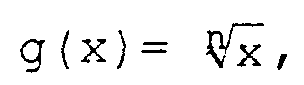
- nonlinear function uses a root function whose Inverse function is the power function, where the Root exponent is greater than 1.
- a root exponent n 2 already brings a significant improvement in Polar pattern, which is increased by enlarging the Root exponent can be increased within limits.
- Choice of the root exponent can be the strength of the Adapt nonlinearity to the task, whereby for n »1 an effect close to clipping is achieved without a threshold must be specified.
- the reception signals of the group of the jointly operated Transducers sampled at a constant sampling frequency and the Direction formation through time delay and addition as well as the Arithmetic operations of the nonlinear function and their Inverse function on the samples of the Receive signals applied.
- the sums of so treated Corresponding samples of the received signals become composed of the group signal. From the multitude of formed group signals, either by using the Procedure on delivered by different converter groups Receive signals (electronic swiveling with cylinder base) or by different time delays of the Receive signals from the same converter group (electronic Swiveling with linear antenna), that determines Group signal with the greatest level the directional characteristic the receiving antenna, the main direction of which is in the direction of incidence of sound waves.
- the receiving antenna 30 is a so-called cylinder base 32 with twenty-one transducers 31 in the exemplary embodiment arranged equidistantly in the circumferential direction on a circular line are.
- the receiving antenna 30 is a so-called cylinder base 32 with twenty-one transducers 31 in the exemplary embodiment arranged equidistantly in the circumferential direction on a circular line are.
- Each of the twenty-one transducers 31 in FIG. 1 belongs to a stave.
- One group of converters each 31, eight transducers 31 in the exemplary embodiment in FIG. 1 or Staves, are operated together.
- the converter group has one Directional pattern, the main direction of which is marked with I. is.
- This directional characteristic of the converter group, too Group characteristic is called for horizontal scanning the antenna environment electronically panned, whereby by Adding and removing a converter 31 in the Converter group the main direction of the directional characteristic can be rotated horizontally by 360 °.
- the so-called electronic panning shifting polar pattern the receiving antenna 30 is exemplary in FIG. 1 marked in their main direction with II and III.
- FIG. 2 is a linear antenna 33 with nine electroacoustic transducers 31 shown.
- the main direction of which is perpendicular to the Converter arrangement stands and is marked with I in Fig. 2.
- This main direction the directional characteristic can be through swivel suitable signal processing electronically, so that the main direction of the polar pattern under one acute angle -90 ° ⁇ ⁇ + 90 ° to the antenna arrangement.
- Two examples of the main direction when swiveled Directional characteristics are in Fig. 2 with II and III characterized. Of course it is also possible to do this Main directions II and III of the directional characteristic of the Linear antenna 33 by mechanical rotation of the Achieve converter arrangement.
- the linear antenna 33 are designed as a surface antenna, for which each of the electroacoustic transducer 31 by further vertically electro-acoustic ones arranged equidistant from each other Converter is added to a so-called stave.
- a sound wave front emitted by a sound source runs across the individual transducers, and they work together operated converter 31 of a converter group deliver on their Output a corresponding electrical output signal, which in the hereinafter referred to as the receive signal.
- the time delays t 1 to t 8 result in a known manner from the distance that the sound wave front travels from the spatial position of the respective transducer 31 to the projection of the transducer 31 on the chord 34.
- a nonlinear function that compresses the value range is applied to each reception signal, and the reverse function is applied to the compressed group signal S and k (k) resulting from the phase addition of the reception signals to equalize it the non-linear function.
- An algebraic sign of the received signals or the compressed group signal before the respective arithmetic operation is added again after the execution of the respective arithmetic operation.
- any function that is strictly monotonic and that compresses the range of values can be used as a non-linear function in order to reduce amplitude differences.
- the root function and its power function are used as the inverse function as the nonlinear function, the root exponent n being greater than 1.
- the squeezed group signal S and k (t) results from adding the amounts of the time-delayed received signals s j (tt j ) while simultaneously securing the sign of the received signals
- the squeezed group signal thus formed is equalized again by exponentiation with the root exponent n and at the same time the sign of the group signal is secured.
- the received signals of the m-operated, electro-acoustic transducers 31 combined into a transducer group are amplified and sampled.
- an amplifier 35 and a scanning unit 36 sample and hold circuit
- the sampling frequency is a multiple of the permitted maximum frequency of the received signals.
- the sampled values or samples are digitized by means of an analog-digital converter 37.
- a square root block 38 the nth root is taken from the amounts of the samples and the sign of the samples is secured in the signum block 39, which is added again by means of a multiplier 40 to the square rooted amounts of the samples taken at the output of the square root block 38.
- the samples distorted by this arithmetic operation are delayed in a time delay element 41 by a defined delay time t j and then fed to a summer 42.
- this process is applied to the received signals of each electroacoustic transducer 31 of the transducer group, the transducers in FIG. 3 being numbered 1, 2 . m are occupied.
- the delay time respectively set in the delay elements 41 is corresponding to t 1 , t 2 to t m and is determined according to FIG. 1.
- the summer 42 the distorted samples are added in phase and with correct sign, the sum being formed in each case via the distorted samples of the m received signals which are assigned to one another.
- the sum formed in the summer 42 is fed to an exponentiation block 43 for equalization, in which the amount of the sum is exponentiated with the root exponent n, and at the same time the sign of the sum is stored in the signum block 44 and then by means of a multiplier 45 the exponentiated amount of the sum added again.
- the individual equalized sums are combined to form a group signal in a signal conditioner 46.
- This group signal forms the directional characteristic of the converter group, consisting of the jointly operated converters 1 - 8, which is also called the group characteristic.
- the same signal processing method can also be applied to the Receive converter 31 of the linear antenna 33 according to FIG. 2 be applied.
- the converter group always consists of the totality of the nine converters 31 operated together electronic swiveling of the directional characteristic of the Linear antenna 33 is done by changing the individual Delay times for the received signals from the converter 31, the 2 from the terms of a Main direction I or II or III incident Sound wave front between the spatial position of the transducers 31 and the transducer projection on a right angle to the Main direction through the first converter 31 Projection line 49 result.
- 4 and 5 are examples of in the display unit 47 in Polar coordinates shown as the polar pattern Receiving antenna 30 designed as a cylinder base 32 according to FIG. 1 shown, for different frequency bands incident sound waves.
- Cylinder base has a diameter of about 3 m and is occupied by ninety-six transducers 31 all around.
Landscapes
- Physics & Mathematics (AREA)
- Engineering & Computer Science (AREA)
- General Physics & Mathematics (AREA)
- Radar, Positioning & Navigation (AREA)
- Remote Sensing (AREA)
- Measurement Of Velocity Or Position Using Acoustic Or Ultrasonic Waves (AREA)
- Measurement Of Mechanical Vibrations Or Ultrasonic Waves (AREA)
Abstract
Description
- Fig. 1
- eine schematische Darstellung einer Draufsicht einer Zylinderbasis mit 21 elektroakustischen Wandlern zur Illustrierung der verschiedenen Wandlergruppen mit gemeinsam betriebenen elektroakustischen Wandlern,
- Fig. 2
- eine schematische Darstellung einer Draufsicht einer Linearantenne mit 9 elektroakustischen Wandlern zur Illustrierung des elektronischen Schwenkens der Richtcharakteristik der Linearantenne,
- Fig. 3
- ein Blockschaltbild einer Schaltungsanordnung zur Illustrierung des Verfahrens zum Bestimmen der Einfallsrichtung von Schallwellen mit der akustischen Empfangsantenne gemäß Fig. 1 oder 2,
- Fig. 4
- jeweils eine Darstellung einer Richtcharakteristik der Empfangsantenne in Fig. 1 in Polarkoordinaten bei der Anwendung herkömmlicher (linearer) Verfahren der Richtungsbildung (links im Bild) und bei Anwendung des erfindungsgemäßen (nichtlinearen) Verfahrens (rechts im Bild) für drei verschiedene Frequenzbereiche der einfallenden Schallwellen,
- Fig. 5
- eine gleiche Darstellung wie in Fig. 4 für weitere drei verschiedene Frequenzbereiche der einfallenden Schallwellen.


Claims (5)
- Verfahren zum Bestimmen der Einfallsrichtung von im Wasser sich ausbreitenden Schallwellen mittels einer eine Mehrzahl von elektroakustischen Wandlern (31) aufweisenden, akustischen Empfangsantenne (30), bei dem fortlaufend die Empfangssignale einer Gruppe von gemeinsam betriebenen Wandlern (31) zur Bildung eines die Richtcharakteristik der Wandlergruppe bestimmenden Gruppensignals zeitverzögert und konphas aufaddiert werden und als Einfallsrichtung die Hauptrichtung der Richtcharakteristik des Gruppensignals mit dem größten Empfangspegel angegeben wird, dadurch gekennzeichnet, daß vor der Addition auf die Empfangssignale eine nichtlineare Funktion, die den Wertebereich staucht, und nach der Addition auf das durch die Addition entstandene, gestauchte Gruppensignal zu dessen Entzerrung die Umkehrfunktion der nichtlinearen Funktion angewendet wird und dabei jeweils ein vor der Rechenoperation vorhandenes Vorzeichen nach der Durchführung der Rechenoperation wieder hinzugefügt wird.
- Verfahren nach Anspruch 1, dadurch gekennzeichnet, daß die nichtlineare Funktion auf die zeitlich verzögerten oder unverzögerten Empfangssignale angewandt wird.
- Verfahren nach Anspruch 1 oder 2, dadurch gekennzeichnet, daß als nichtlineare Funktion eine Wurzelfunktionderen Umkehrfunktion die Potenzfunktion g'(x) = xn ist, angewendet wird, wobei der Wurzelexponent (n) größer 1 ist.
- Verfahren nach einem der Ansprüche 1 - 3, dadurch gekennzeichnet, daß die Empfangssignale mit einer konstanten Abtastfrequenz abgetastet und die Zeitverzögerung und Addition sowie die Rechenoperationen der nichtlinearen Funktion und deren Umkehrfunktion auf die Abtastwerte angewendet werden.
- Verfahren nach Anspruch 3 und 4, dadurch gekennzeichnet, daß die Beträge der Abtastwerte radiziert und die den Abtastwerten zugehörigen Vorzeichen den radizierten Beträgen der Abtastwerte wieder hinzugefügt werden und daß der Betrag der Summe der vorzeichenrichtig addierten Beträge der Abtastwerte mit dem Wurzelexponenten (n) potenziert und das vor dem Potenzieren vorhandene Vorzeichen der Summe dem in die Potenz erhobenen Betrag der Summe wieder hinzugefügt wird.
Applications Claiming Priority (2)
| Application Number | Priority Date | Filing Date | Title |
|---|---|---|---|
| DE10027538 | 2000-06-02 | ||
| DE10027538A DE10027538C1 (de) | 2000-06-02 | 2000-06-02 | Verfahren zum Bestimmen der Einfallsrichtung von Schallwellen |
Publications (2)
| Publication Number | Publication Date |
|---|---|
| EP1160581A1 true EP1160581A1 (de) | 2001-12-05 |
| EP1160581B1 EP1160581B1 (de) | 2005-02-16 |
Family
ID=7644572
Family Applications (1)
| Application Number | Title | Priority Date | Filing Date |
|---|---|---|---|
| EP01109902A Expired - Lifetime EP1160581B1 (de) | 2000-06-02 | 2001-04-24 | Verfahren zum Bestimmen der Einfallsrichtung von Schallwellen |
Country Status (3)
| Country | Link |
|---|---|
| EP (1) | EP1160581B1 (de) |
| AT (1) | ATE289420T1 (de) |
| DE (2) | DE10027538C1 (de) |
Cited By (1)
| Publication number | Priority date | Publication date | Assignee | Title |
|---|---|---|---|---|
| WO2007124797A1 (de) * | 2006-04-27 | 2007-11-08 | Atlas Elektronik Gmbh | Verfahren zur peilung von schallabstrahlenden zielen |
Families Citing this family (6)
| Publication number | Priority date | Publication date | Assignee | Title |
|---|---|---|---|---|
| DE10332886B3 (de) * | 2003-07-19 | 2004-12-30 | Atlas Elektronik Gmbh | Verfahren zum Bestimmen von Zieldaten mit einer Aktiv-Sonaranlage |
| DE10353292B3 (de) * | 2003-11-14 | 2005-05-19 | Atlas Elektronik Gmbh | Verfahren zur Bildung eines Gruppensignals |
| DE10356577B4 (de) * | 2003-12-04 | 2006-04-06 | Atlas Elektronik Gmbh | Verfahren zum Aussenden und Empfangen von Wellenenergie |
| US9271697B2 (en) | 2008-03-21 | 2016-03-01 | Boston Scientific Scimed, Inc. | Ultrasound imaging with speckle suppression via direct rectification of signals |
| DE102011117591B4 (de) | 2011-11-03 | 2013-12-24 | Atlas Elektronik Gmbh | Verfahren und Vorrichtung zum Korrigieren systematischer Peilfehler |
| DE102012008085B4 (de) * | 2012-04-20 | 2013-11-07 | Atlas Elektronik Gmbh | Verfahren und Vorrichtung zum räumlichen Filtern von Schallwellen |
Citations (4)
| Publication number | Priority date | Publication date | Assignee | Title |
|---|---|---|---|---|
| US4488434A (en) * | 1983-05-13 | 1984-12-18 | General Electric Company | Phase insensitive detector for use in ultrasonic scanner and method |
| JPH0694827A (ja) * | 1992-09-09 | 1994-04-08 | Furuno Electric Co Ltd | ビームフォーミング回路 |
| JPH07198819A (ja) * | 1993-12-28 | 1995-08-01 | Tokimec Inc | 電波到来方向探知装置 |
| EP0964264A2 (de) * | 1998-06-10 | 1999-12-15 | STN ATLAS Elektronik GmbH | Verfahren zur Bestimmung der Tiefe von getauchten Schallquellen |
Family Cites Families (2)
| Publication number | Priority date | Publication date | Assignee | Title |
|---|---|---|---|---|
| DE2114373C3 (de) * | 1971-03-25 | 1980-04-17 | Fried. Krupp Gmbh, 4300 Essen | Schaltanordnung zum Bilden von Gruppensignalen in der Peiltechnik unter Verwendung von Verzögerungsschaltungen |
| US4060792A (en) * | 1976-06-17 | 1977-11-29 | Raytheon Company | Hard clipped beam former |
-
2000
- 2000-06-02 DE DE10027538A patent/DE10027538C1/de not_active Expired - Fee Related
-
2001
- 2001-04-24 EP EP01109902A patent/EP1160581B1/de not_active Expired - Lifetime
- 2001-04-24 AT AT01109902T patent/ATE289420T1/de not_active IP Right Cessation
- 2001-04-24 DE DE50105344T patent/DE50105344D1/de not_active Expired - Lifetime
Patent Citations (4)
| Publication number | Priority date | Publication date | Assignee | Title |
|---|---|---|---|---|
| US4488434A (en) * | 1983-05-13 | 1984-12-18 | General Electric Company | Phase insensitive detector for use in ultrasonic scanner and method |
| JPH0694827A (ja) * | 1992-09-09 | 1994-04-08 | Furuno Electric Co Ltd | ビームフォーミング回路 |
| JPH07198819A (ja) * | 1993-12-28 | 1995-08-01 | Tokimec Inc | 電波到来方向探知装置 |
| EP0964264A2 (de) * | 1998-06-10 | 1999-12-15 | STN ATLAS Elektronik GmbH | Verfahren zur Bestimmung der Tiefe von getauchten Schallquellen |
Non-Patent Citations (2)
| Title |
|---|
| PATENT ABSTRACTS OF JAPAN vol. 018, no. 356 (P - 1765) 5 July 1994 (1994-07-05) * |
| PATENT ABSTRACTS OF JAPAN vol. 1995, no. 11 26 December 1995 (1995-12-26) * |
Cited By (3)
| Publication number | Priority date | Publication date | Assignee | Title |
|---|---|---|---|---|
| WO2007124797A1 (de) * | 2006-04-27 | 2007-11-08 | Atlas Elektronik Gmbh | Verfahren zur peilung von schallabstrahlenden zielen |
| AU2007245931B2 (en) * | 2006-04-27 | 2010-03-04 | Atlas Elektronik Gmbh | Process for locating sound projecting targets |
| KR101025859B1 (ko) * | 2006-04-27 | 2011-03-30 | 아틀라스 엘렉트로닉 게엠베하 | 음향 발신 타겟을 로케이팅하는 방법 |
Also Published As
| Publication number | Publication date |
|---|---|
| DE50105344D1 (de) | 2005-03-24 |
| DE10027538C1 (de) | 2001-10-31 |
| EP1160581B1 (de) | 2005-02-16 |
| ATE289420T1 (de) | 2005-03-15 |
Similar Documents
| Publication | Publication Date | Title |
|---|---|---|
| DE2903045C2 (de) | Einrichtung zur Bildung einer Richtcharakteristik einer Wandleranordnung | |
| DE602004012620T2 (de) | Digitalisiereranordnung | |
| DE2819880C2 (de) | Empfänger für ein Gerät zur kohärenten Puls-Doppler-Rückstrahlortung | |
| DE69106049T2 (de) | Ultraschallbildgerät mit adaptiver Phasenaberrationskorrektur. | |
| DE2727551C2 (de) | Empfangseinrichtung bestehend aus einer Gruppe von elektromagnetischen Wandlern | |
| DE19756686A1 (de) | Verfahren und Einrichtung zur komplexen Bandpassfilterung und Dezimierung in einem Ultraschall-Strahlbündelformer | |
| DE2753615C2 (de) | Elektromagnetisches oder akustisches Wandlerfeld mit einer Einrichtung zur Bildung mindestens eines Empfangsrichtstrahles | |
| EP2469507A1 (de) | Akustische Unterwasserantenne, U-Boot mit derartiger Antenne sowie Verfahren zum Peilen, Orten und/oder Klassifizieren eines Ziels mittels einer derartigen Antenne | |
| DE69015565T2 (de) | Ultraschallprüfvorrichtung. | |
| DE10027538C1 (de) | Verfahren zum Bestimmen der Einfallsrichtung von Schallwellen | |
| DE19648327B4 (de) | Verfahren zur Richtstrahlbildung in Peilanlagen und Vorrichtung zur Durchführung des Verfahrens | |
| DE10353292B3 (de) | Verfahren zur Bildung eines Gruppensignals | |
| DE2202517C3 (de) | Verfahren zur Peilung periodisch wiederkehrender impulsförmiger Signale | |
| EP2472282B1 (de) | Verfahren zum Bestimmem einer oder mehrerer relativer Richtungen als Zielpeilung oder Zielpeilungen sowie Vorrichtung zur Ausführung des Verfahrens | |
| EP1176428B1 (de) | Verfahren zur Verbesserung des Signal/Stör-Verhältnisses einer Sonargruppe | |
| DE2625719C1 (de) | Ortungssystem mit getrennt aufgestellten Sensoren zur Schnittbildung zwischen einer Hyperbel (Laufzeitdifferenz) und einer Geraden | |
| EP3082273B1 (de) | Verfahren und vorrichtung zur reduktion von korrelierten störsignalen in mehrkanal-empfängersystemen mit digitaler strahlformung | |
| DE10153443C1 (de) | Verfahren zur passiven Ortung von schallabstrahlenden Zielen | |
| EP1107016B1 (de) | Verfahren zur Detektion und Ortung von Zielen | |
| DE2516001C2 (de) | Verfahren zur Verbesserung der Richtcharakteristik einer ebenen Echolot- Empfangsbasis und Vorrichtung zum Ausüben dieses Verfahrens | |
| EP2480907B1 (de) | Verfahren und vorrichtung zum peilen von schallabstrahlenden zielen | |
| EP1001275A2 (de) | Vorrichtung zum Bestimmen der Einfallsrichtung von zeitlich begrenzt auftretenden Schallwellen | |
| DE102017100909B4 (de) | Schätzung eines Einfallswinkels | |
| DE3048240C2 (de) | ||
| DE2114373B2 (de) | Schaltanordnung zum Bilden von Gruppensignalen in der Peiltechnik unter Verwendung von Verzögerungsschaltungen |
Legal Events
| Date | Code | Title | Description |
|---|---|---|---|
| PUAI | Public reference made under article 153(3) epc to a published international application that has entered the european phase |
Free format text: ORIGINAL CODE: 0009012 |
|
| AK | Designated contracting states |
Kind code of ref document: A1 Designated state(s): DE FR GB NL Kind code of ref document: A1 Designated state(s): AT BE CH CY DE DK ES FI FR GB GR IE IT LI LU MC NL PT SE TR |
|
| AX | Request for extension of the european patent |
Free format text: AL;LT;LV;MK;RO;SI |
|
| 17P | Request for examination filed |
Effective date: 20020416 |
|
| AKX | Designation fees paid |
Free format text: DE FR GB NL |
|
| RBV | Designated contracting states (corrected) |
Designated state(s): AT BE CH CY DE DK ES FI FR GB GR IE IT LI LU MC NL PT SE |
|
| RAP1 | Party data changed (applicant data changed or rights of an application transferred) |
Owner name: ATLAS ELEKTRONIK GMBH |
|
| GRAP | Despatch of communication of intention to grant a patent |
Free format text: ORIGINAL CODE: EPIDOSNIGR1 |
|
| RBV | Designated contracting states (corrected) |
Designated state(s): AT BE CH CY DE DK ES FI FR GB GR IE IT LI LU MC NL PT SE TR |
|
| GRAS | Grant fee paid |
Free format text: ORIGINAL CODE: EPIDOSNIGR3 |
|
| GRAA | (expected) grant |
Free format text: ORIGINAL CODE: 0009210 |
|
| AK | Designated contracting states |
Kind code of ref document: B1 Designated state(s): AT BE CH CY DE DK ES FI FR GB GR IE IT LI LU MC NL PT SE TR |
|
| PG25 | Lapsed in a contracting state [announced via postgrant information from national office to epo] |
Ref country code: IT Free format text: LAPSE BECAUSE OF FAILURE TO SUBMIT A TRANSLATION OF THE DESCRIPTION OR TO PAY THE FEE WITHIN THE PRESCRIBED TIME-LIMIT;WARNING: LAPSES OF ITALIAN PATENTS WITH EFFECTIVE DATE BEFORE 2007 MAY HAVE OCCURRED AT ANY TIME BEFORE 2007. THE CORRECT EFFECTIVE DATE MAY BE DIFFERENT FROM THE ONE RECORDED. Effective date: 20050216 Ref country code: IE Free format text: LAPSE BECAUSE OF FAILURE TO SUBMIT A TRANSLATION OF THE DESCRIPTION OR TO PAY THE FEE WITHIN THE PRESCRIBED TIME-LIMIT Effective date: 20050216 Ref country code: FI Free format text: LAPSE BECAUSE OF FAILURE TO SUBMIT A TRANSLATION OF THE DESCRIPTION OR TO PAY THE FEE WITHIN THE PRESCRIBED TIME-LIMIT Effective date: 20050216 Ref country code: TR Free format text: LAPSE BECAUSE OF FAILURE TO SUBMIT A TRANSLATION OF THE DESCRIPTION OR TO PAY THE FEE WITHIN THE PRESCRIBED TIME-LIMIT Effective date: 20050216 |
|
| REG | Reference to a national code |
Ref country code: GB Ref legal event code: FG4D Free format text: NOT ENGLISH |
|
| REG | Reference to a national code |
Ref country code: CH Ref legal event code: EP |
|
| REG | Reference to a national code |
Ref country code: IE Ref legal event code: FG4D Free format text: GERMAN |
|
| REF | Corresponds to: |
Ref document number: 50105344 Country of ref document: DE Date of ref document: 20050324 Kind code of ref document: P |
|
| GBT | Gb: translation of ep patent filed (gb section 77(6)(a)/1977) |
Effective date: 20050319 |
|
| PG25 | Lapsed in a contracting state [announced via postgrant information from national office to epo] |
Ref country code: AT Free format text: LAPSE BECAUSE OF NON-PAYMENT OF DUE FEES Effective date: 20050424 Ref country code: CY Free format text: LAPSE BECAUSE OF FAILURE TO SUBMIT A TRANSLATION OF THE DESCRIPTION OR TO PAY THE FEE WITHIN THE PRESCRIBED TIME-LIMIT Effective date: 20050424 Ref country code: LU Free format text: LAPSE BECAUSE OF NON-PAYMENT OF DUE FEES Effective date: 20050424 |
|
| PG25 | Lapsed in a contracting state [announced via postgrant information from national office to epo] |
Ref country code: BE Free format text: LAPSE BECAUSE OF NON-PAYMENT OF DUE FEES Effective date: 20050430 Ref country code: MC Free format text: LAPSE BECAUSE OF NON-PAYMENT OF DUE FEES Effective date: 20050430 Ref country code: LI Free format text: LAPSE BECAUSE OF NON-PAYMENT OF DUE FEES Effective date: 20050430 Ref country code: CH Free format text: LAPSE BECAUSE OF NON-PAYMENT OF DUE FEES Effective date: 20050430 |
|
| PG25 | Lapsed in a contracting state [announced via postgrant information from national office to epo] |
Ref country code: DK Free format text: LAPSE BECAUSE OF FAILURE TO SUBMIT A TRANSLATION OF THE DESCRIPTION OR TO PAY THE FEE WITHIN THE PRESCRIBED TIME-LIMIT Effective date: 20050516 Ref country code: GR Free format text: LAPSE BECAUSE OF FAILURE TO SUBMIT A TRANSLATION OF THE DESCRIPTION OR TO PAY THE FEE WITHIN THE PRESCRIBED TIME-LIMIT Effective date: 20050516 Ref country code: SE Free format text: LAPSE BECAUSE OF FAILURE TO SUBMIT A TRANSLATION OF THE DESCRIPTION OR TO PAY THE FEE WITHIN THE PRESCRIBED TIME-LIMIT Effective date: 20050516 |
|
| PG25 | Lapsed in a contracting state [announced via postgrant information from national office to epo] |
Ref country code: ES Free format text: LAPSE BECAUSE OF FAILURE TO SUBMIT A TRANSLATION OF THE DESCRIPTION OR TO PAY THE FEE WITHIN THE PRESCRIBED TIME-LIMIT Effective date: 20050527 |
|
| PG25 | Lapsed in a contracting state [announced via postgrant information from national office to epo] |
Ref country code: PT Free format text: LAPSE BECAUSE OF FAILURE TO SUBMIT A TRANSLATION OF THE DESCRIPTION OR TO PAY THE FEE WITHIN THE PRESCRIBED TIME-LIMIT Effective date: 20050718 |
|
| REG | Reference to a national code |
Ref country code: IE Ref legal event code: FD4D |
|
| BERE | Be: lapsed |
Owner name: ATLAS ELEKTRONIK G.M.B.H. Effective date: 20050430 |
|
| REG | Reference to a national code |
Ref country code: CH Ref legal event code: PL |
|
| ET | Fr: translation filed | ||
| PLBE | No opposition filed within time limit |
Free format text: ORIGINAL CODE: 0009261 |
|
| STAA | Information on the status of an ep patent application or granted ep patent |
Free format text: STATUS: NO OPPOSITION FILED WITHIN TIME LIMIT |
|
| 26N | No opposition filed |
Effective date: 20051117 |
|
| BERE | Be: lapsed |
Owner name: ATLAS ELEKTRONIK G.M.B.H. Effective date: 20050430 |
|
| PGFP | Annual fee paid to national office [announced via postgrant information from national office to epo] |
Ref country code: FR Payment date: 20100506 Year of fee payment: 10 |
|
| PGFP | Annual fee paid to national office [announced via postgrant information from national office to epo] |
Ref country code: NL Payment date: 20100413 Year of fee payment: 10 Ref country code: DE Payment date: 20100423 Year of fee payment: 10 |
|
| PGFP | Annual fee paid to national office [announced via postgrant information from national office to epo] |
Ref country code: GB Payment date: 20100420 Year of fee payment: 10 |
|
| REG | Reference to a national code |
Ref country code: DE Ref legal event code: R119 Ref document number: 50105344 Country of ref document: DE |
|
| REG | Reference to a national code |
Ref country code: DE Ref legal event code: R119 Ref document number: 50105344 Country of ref document: DE |
|
| REG | Reference to a national code |
Ref country code: NL Ref legal event code: V1 Effective date: 20111101 |
|
| GBPC | Gb: european patent ceased through non-payment of renewal fee |
Effective date: 20110424 |
|
| REG | Reference to a national code |
Ref country code: FR Ref legal event code: ST Effective date: 20111230 |
|
| PG25 | Lapsed in a contracting state [announced via postgrant information from national office to epo] |
Ref country code: NL Free format text: LAPSE BECAUSE OF NON-PAYMENT OF DUE FEES Effective date: 20111101 Ref country code: FR Free format text: LAPSE BECAUSE OF NON-PAYMENT OF DUE FEES Effective date: 20110502 |
|
| PG25 | Lapsed in a contracting state [announced via postgrant information from national office to epo] |
Ref country code: GB Free format text: LAPSE BECAUSE OF NON-PAYMENT OF DUE FEES Effective date: 20110424 |
|
| PG25 | Lapsed in a contracting state [announced via postgrant information from national office to epo] |
Ref country code: DE Free format text: LAPSE BECAUSE OF NON-PAYMENT OF DUE FEES Effective date: 20111031 |