EP1160479A2 - Modular brake mechanism - Google Patents
Modular brake mechanism Download PDFInfo
- Publication number
- EP1160479A2 EP1160479A2 EP01112017A EP01112017A EP1160479A2 EP 1160479 A2 EP1160479 A2 EP 1160479A2 EP 01112017 A EP01112017 A EP 01112017A EP 01112017 A EP01112017 A EP 01112017A EP 1160479 A2 EP1160479 A2 EP 1160479A2
- Authority
- EP
- European Patent Office
- Prior art keywords
- brake mechanism
- brake
- lever
- cross bar
- module
- Prior art date
- Legal status (The legal status is an assumption and is not a legal conclusion. Google has not performed a legal analysis and makes no representation as to the accuracy of the status listed.)
- Granted
Links
Images




Classifications
-
- F—MECHANICAL ENGINEERING; LIGHTING; HEATING; WEAPONS; BLASTING
- F16—ENGINEERING ELEMENTS AND UNITS; GENERAL MEASURES FOR PRODUCING AND MAINTAINING EFFECTIVE FUNCTIONING OF MACHINES OR INSTALLATIONS; THERMAL INSULATION IN GENERAL
- F16D—COUPLINGS FOR TRANSMITTING ROTATION; CLUTCHES; BRAKES
- F16D65/00—Parts or details
- F16D65/14—Actuating mechanisms for brakes; Means for initiating operation at a predetermined position
- F16D65/16—Actuating mechanisms for brakes; Means for initiating operation at a predetermined position arranged in or on the brake
- F16D65/18—Actuating mechanisms for brakes; Means for initiating operation at a predetermined position arranged in or on the brake adapted for drawing members together, e.g. for disc brakes
-
- F—MECHANICAL ENGINEERING; LIGHTING; HEATING; WEAPONS; BLASTING
- F16—ENGINEERING ELEMENTS AND UNITS; GENERAL MEASURES FOR PRODUCING AND MAINTAINING EFFECTIVE FUNCTIONING OF MACHINES OR INSTALLATIONS; THERMAL INSULATION IN GENERAL
- F16D—COUPLINGS FOR TRANSMITTING ROTATION; CLUTCHES; BRAKES
- F16D65/00—Parts or details
- F16D65/14—Actuating mechanisms for brakes; Means for initiating operation at a predetermined position
- F16D65/16—Actuating mechanisms for brakes; Means for initiating operation at a predetermined position arranged in or on the brake
- F16D65/18—Actuating mechanisms for brakes; Means for initiating operation at a predetermined position arranged in or on the brake adapted for drawing members together, e.g. for disc brakes
- F16D65/183—Actuating mechanisms for brakes; Means for initiating operation at a predetermined position arranged in or on the brake adapted for drawing members together, e.g. for disc brakes with force-transmitting members arranged side by side acting on a spot type force-applying member
-
- F—MECHANICAL ENGINEERING; LIGHTING; HEATING; WEAPONS; BLASTING
- F16—ENGINEERING ELEMENTS AND UNITS; GENERAL MEASURES FOR PRODUCING AND MAINTAINING EFFECTIVE FUNCTIONING OF MACHINES OR INSTALLATIONS; THERMAL INSULATION IN GENERAL
- F16D—COUPLINGS FOR TRANSMITTING ROTATION; CLUTCHES; BRAKES
- F16D65/00—Parts or details
- F16D65/38—Slack adjusters
- F16D65/40—Slack adjusters mechanical
- F16D65/52—Slack adjusters mechanical self-acting in one direction for adjusting excessive play
- F16D65/56—Slack adjusters mechanical self-acting in one direction for adjusting excessive play with screw-thread and nut
- F16D65/567—Slack adjusters mechanical self-acting in one direction for adjusting excessive play with screw-thread and nut for mounting on a disc brake
- F16D65/568—Slack adjusters mechanical self-acting in one direction for adjusting excessive play with screw-thread and nut for mounting on a disc brake for synchronous adjustment of actuators arranged in parallel
-
- F—MECHANICAL ENGINEERING; LIGHTING; HEATING; WEAPONS; BLASTING
- F16—ENGINEERING ELEMENTS AND UNITS; GENERAL MEASURES FOR PRODUCING AND MAINTAINING EFFECTIVE FUNCTIONING OF MACHINES OR INSTALLATIONS; THERMAL INSULATION IN GENERAL
- F16D—COUPLINGS FOR TRANSMITTING ROTATION; CLUTCHES; BRAKES
- F16D55/00—Brakes with substantially-radial braking surfaces pressed together in axial direction, e.g. disc brakes
- F16D2055/0004—Parts or details of disc brakes
- F16D2055/0016—Brake calipers
-
- F—MECHANICAL ENGINEERING; LIGHTING; HEATING; WEAPONS; BLASTING
- F16—ENGINEERING ELEMENTS AND UNITS; GENERAL MEASURES FOR PRODUCING AND MAINTAINING EFFECTIVE FUNCTIONING OF MACHINES OR INSTALLATIONS; THERMAL INSULATION IN GENERAL
- F16D—COUPLINGS FOR TRANSMITTING ROTATION; CLUTCHES; BRAKES
- F16D55/00—Brakes with substantially-radial braking surfaces pressed together in axial direction, e.g. disc brakes
- F16D2055/0004—Parts or details of disc brakes
- F16D2055/0037—Protective covers
-
- F—MECHANICAL ENGINEERING; LIGHTING; HEATING; WEAPONS; BLASTING
- F16—ENGINEERING ELEMENTS AND UNITS; GENERAL MEASURES FOR PRODUCING AND MAINTAINING EFFECTIVE FUNCTIONING OF MACHINES OR INSTALLATIONS; THERMAL INSULATION IN GENERAL
- F16D—COUPLINGS FOR TRANSMITTING ROTATION; CLUTCHES; BRAKES
- F16D2121/00—Type of actuator operation force
- F16D2121/14—Mechanical
-
- F—MECHANICAL ENGINEERING; LIGHTING; HEATING; WEAPONS; BLASTING
- F16—ENGINEERING ELEMENTS AND UNITS; GENERAL MEASURES FOR PRODUCING AND MAINTAINING EFFECTIVE FUNCTIONING OF MACHINES OR INSTALLATIONS; THERMAL INSULATION IN GENERAL
- F16D—COUPLINGS FOR TRANSMITTING ROTATION; CLUTCHES; BRAKES
- F16D2125/00—Components of actuators
- F16D2125/18—Mechanical mechanisms
- F16D2125/20—Mechanical mechanisms converting rotation to linear movement or vice versa
- F16D2125/22—Mechanical mechanisms converting rotation to linear movement or vice versa acting transversely to the axis of rotation
- F16D2125/26—Cranks
-
- F—MECHANICAL ENGINEERING; LIGHTING; HEATING; WEAPONS; BLASTING
- F16—ENGINEERING ELEMENTS AND UNITS; GENERAL MEASURES FOR PRODUCING AND MAINTAINING EFFECTIVE FUNCTIONING OF MACHINES OR INSTALLATIONS; THERMAL INSULATION IN GENERAL
- F16D—COUPLINGS FOR TRANSMITTING ROTATION; CLUTCHES; BRAKES
- F16D2125/00—Components of actuators
- F16D2125/18—Mechanical mechanisms
- F16D2125/58—Mechanical mechanisms transmitting linear movement
- F16D2125/64—Levers
-
- F—MECHANICAL ENGINEERING; LIGHTING; HEATING; WEAPONS; BLASTING
- F16—ENGINEERING ELEMENTS AND UNITS; GENERAL MEASURES FOR PRODUCING AND MAINTAINING EFFECTIVE FUNCTIONING OF MACHINES OR INSTALLATIONS; THERMAL INSULATION IN GENERAL
- F16D—COUPLINGS FOR TRANSMITTING ROTATION; CLUTCHES; BRAKES
- F16D2125/00—Components of actuators
- F16D2125/18—Mechanical mechanisms
- F16D2125/58—Mechanical mechanisms transmitting linear movement
- F16D2125/68—Lever-link mechanisms, e.g. toggles with change of force ratio
-
- F—MECHANICAL ENGINEERING; LIGHTING; HEATING; WEAPONS; BLASTING
- F16—ENGINEERING ELEMENTS AND UNITS; GENERAL MEASURES FOR PRODUCING AND MAINTAINING EFFECTIVE FUNCTIONING OF MACHINES OR INSTALLATIONS; THERMAL INSULATION IN GENERAL
- F16D—COUPLINGS FOR TRANSMITTING ROTATION; CLUTCHES; BRAKES
- F16D2250/00—Manufacturing; Assembly
- F16D2250/0084—Assembly or disassembly
Definitions
- the present invention concerns a modular brake mechanism for a disc brake.
- the brake mechanism is to be received in some kind of a caliper.
- the brake mechanism according to the present invention is primarily intended for a heavy road vehicle but may quite as well be used for a lighter road vehicle or a rail vehicle.
- One object of the present invention is to facilitate the replacement of different parts of the brake mechanism that show different wear.
- the bellows may be put under more stress than normal and have to be changed more often.
- the adjuster mechanism synchronisation gears and bearings may have a higher wear than other parts.
- assembly of the brake mechanism may be easier for certain calipers if it is possible to assemble the mechanism in two or more units.
- the brake mechanism of the present invention is preferably pneumatically actuated, but it may also be hydraulically or electrically actuated.
- front side when used in connection with the caliper stands for the side of the caliper facing the brake disc.
- rear side stands for the opposite side. This also applies for similar expressions.
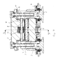
- a first embodiment for a modular brake mechanism according to the present invention is shown in Figs. 1 and 2.
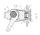
- a second embodiment for a modular brake mechanism is shown in Figs. 3 to 5.
- a third embodiment for a modular brake mechanism is shown in Fig. 6.
- the main components of the brake mechanism of the invention are a lever 1, a bearing bracket 2, a cross bar 3, adjustment screws 4, thrust plates 5, reset and adjustment shafts 6, a closing plate 7, a synchronisation shaft 8, pinions 9, crown wheels 10, a return spring 11, an adjuster mechanism 12 and bellows 15.
- the lever 1 acts on a cross bar 3.
- the lever 1 is supported by roller bearings 20 placed in a bearing bracket 2 to be received in a brake caliper (not shown) and the cross bar 3, respectively.
- the lever 1 is received in bearings placed directly in the caliper, i.e. without the use of any bearing bracket.
- the roller bearings are replaced by plain bearings.
- the brake force from the piston rod of the brake cylinder (not shown) is transmitted to the mechanism, especially the cross bar 3, by means of the lever 1.
- the lever 1 consists in essence of an arm extending out from what could be called a curved wedge 33 having cylindrical surfaces in engagement with corresponding cylindrical surfaces of the cross bar 3 and bearing bracket 2.
- the inner cylindrical surface of the curved wedge 33 co-operates with the bearing bracket 2, whereas the outer cylindrical surface with larger radius than the inner cylindrical surface co-operates with the cross bar 3.
- the centres for these two cylindrical surfaces are offset in relation to each other.
- a portion of the bearing bracket 2 functions as a cover 32 for an opening at the rear of the caliper.
- the bearing bracket 2 has no cover as it is intend for use in a caliper having no opening in the rear side. (Cf. Fig. 7)
- the cross bar 3 has two threaded openings each receiving an adjustment screw 4.
- the adjustment screws 4 are rotatably mounted in the cross bar 3.
- Each adjustment screw 4 is provided with a thrust plate 5, which is to act on a brake pad holder (not shown) or the like.
- the brake pad will go into contact with the brake disc during activation of the brake.
- a further brake pad is arranged on the opposite side of the brake disc.
- the further brake pad is in a known way brought into contact with the brake disc in that the caliper is moved at the activation of the brake.
- the brake mechanism comprises a closing plate 7 fixed to the caliper at assembly.
- the closing plate 7 is fixed to the caliper by means of screws.
- the closing plate 7 is used to close the opening on the front side of the caliper.
- a return spring 11 is positioned between the closing plate 7 and the cross bar 3 in order to bring the brake mechanism back to its rest position.
- the brake mechanism includes a synchronising shaft 8, having pinions 9 at each end.
- the pinions 9 are coupled to crown wheels 10 non-rotatably connected to the adjustment and reset shafts 6.
- the synchronising shaft 8 carries an adjuster mechanism 12 of known design.
- the pinions 9, crown wheels 10, synchronising shaft 8 and the adjuster mechanism 12 form a synchronising unit, synchronising the movements of the adjustment and reset shafts 6.
- the adjustment and reset shafts 6 are furnished with suitable heads to receive a tool used to reset the thrust units when the brake pad is to be replaced.
- a removable cap 35 is normally placed over the head for protection.
- bellows 15 are placed between the thrust plates 5 and the closing plate 7.
- the bellows 15 are placed in a heat protection ring.
- the closing plate 7 has openings to receive the thrust units. There is a clearance between the closing plate 7 and the thrust units allowing the thrust units to move in any direction in relation to the closing plate 7.
- one module or unit consists of the lever 1, the bearing bracket 2 including the synchronisation unit and the adjustment and reset shafts 6.
- the lever 1 is held at the bearing bracket 2 by means of clips 13, corresponding to the clips of the third embodiment shown in Fig. 6.
- the adjustment and reset shafts 6 are received in openings of the bearing bracket 2. In embodiments without any bearing bracket the shafts 6 are received directly in the caliper (not shown).
- the cross bar 3, the closing plate 7, the return spring 11, the adjustment screws 4, the bellows 15 and the thrust plates 5 form the second unit of the brake mechanism.
- the second unit is held together by means of a brace 14.
- the brace 14 goes around the cross bar 3 and the ends of the brace are received in openings of the closing plate 7.
- the adjuster mechanism 12, synchronisation gears 9,10 and bearings 20 have a higher wear than other parts in the mechanism. It is therefore an advantage to be able to supply a module comprising these parts, as shown in the embodiment of Figs. 1 and 2, as a spare part.
- the lever 1, the bearing bracket 2 including the synchronisation unit, the cross bar 3, the adjustment screws 4, and the adjustment and reset shafts 6 form the first module or unit of the brake mechanism.
- This first unit is held together by a brace 16.
- the brace 16 is made of two halves and the ends of the brace 16 are received in openings of the cross bar 3 and the bearing bracket, respectively.
- the second module or unit includes the closing plate 7, the return spring 11, the bellows 15 and the thrust plates 5.
- the thrust plates 5 are received and held in the bellows 15.
- the thrust plates 5 have a pin 18, which is received in the adjustment screws 4.
- the pin 18 of each thrust plate 5 is pressed into each adjustment screw 4 at assembly and is held in the adjustment screw 4 by means of a force fit, given by an elastic ring 19 on the pin 18.
- the return spring 11 is held at the closing plate 7 by means of a force fit.
- the module including the lever 1 is normally first brought into the caliper, then the other module is brought in and the closing plate 7 is fixed to the caliper. After assembly the brake mechanism will be held together within the brake caliper by screws fixing the closing plate 7 to the caliper.
- the different units of the brake mechanism consist of other parts, i.e. the brake mechanism may be divided in different locations, and the brake mechanism may be divided into more than two units. Normally the brake mechanism consists of at least two units. A person skilled in the art realises, e.g., that the brake mechanism may be divided into three modules if the brake mechanism is divided in both positions of the above embodiments.
- the brake mechanism of the embodiment according to Fig. 6 comprises as main components a lever 21, a bearing bracket 22, a cross bar 23, gear wheels 24, bellows, a thrust plate 25, a reset shaft 26, a closing plate 27, adjustment screws 29 and an adjustment mechanism 30.
- a portion of the bearing bracket 22 functions as a cover 32 for an opening at the rear of the caliper.
- the first module is formed of the lever 21 attached to the bearing bracket 22 by means of clips 13.
- the second unit comprises the rest of the above main components, i.e. the cross bar 23, the gear wheels 24, the bellows, the thrust plate 25, the reset shaft 26, the closing plate 27, the adjustment screws 29 and the adjustment mechanism 30.
- the cross bar 23 receives two thrust units. Each thrust unit comprises an adjustment screw 29. One of the thrust units is further furnished with an adjuster mechanism 30 and an adjuster shaft. The adjuster mechanism 30 is placed on top of the adjustment screw. The other thrust unit is furnished with a reset shaft 26.
- the adjustment screws are drivingly connected by means of a set of gear wheels 24.
- the set of gear wheels 24 are placed between the closing plate 27 and the cross bar 23.
- the thrust units are connected with a common thrust plate 25, which thrust plate 25 acts on a brake pad (not shown).
- the reset shaft 26 is furnished with a suitable head to receive a tool used to reset the thrust units when the brake pads are to be replaced. This movement will be transferred to the adjuster shaft by means of the set of gear wheels 24.
- the second module is kept together before assembly by a brace 31.
- the brace 31 surrounds the cross bar 23 and the ends of the brace 31 are received in openings of the closing plate 27 (cf. Fig. 2).
- the adjuster mechanism 30 is of a known construction.
- the adjuster mechanism 30 co-operates with the lever 21 by means of a lever pin received in a groove 28 of the adjuster mechanism 30.
- the lever pin will act on the adjuster mechanism 30 via the groove 28. But as this is not part of the present invention it will not be further described here.
- the module including the lever 21 is normally first brought into the caliper, then the other module is brought in and the closing plate 27 is fixed to the caliper. After assembly the brake mechanism will be held together within the brake caliper by screws fixing the closing plate 27 to the caliper.
- the brake mechanism of Fig. 7 is intended for use when the caliper has no opening in the rear side.
- the bearing bracket 34 of said embodiment has no part corresponding to the cover 32 of the bearing brackets 2,22 of the previous embodiments.
- the embodiment of Fig. 7 is identical with the other embodiments.
- the embodiment of Fig. 7 is of a modular form comprising two or more modules or units. Each module comprises at least two components.
Landscapes
- Engineering & Computer Science (AREA)
- General Engineering & Computer Science (AREA)
- Mechanical Engineering (AREA)
- Braking Arrangements (AREA)
Abstract
Description
Claims (7)
- A brake mechanism for a disc brake which brake mechanism is received in a caliper having an opening at least in the front side, the brake mechanism comprises a brake lever (1,21), a cross bar (3,23) operationally connected to the brake lever (1,21), one or more thrust plates (5,25) at the cross bar (3,23) and a closing plate (7,27) for closing of the opening in the front side of the caliper, and whereby the cross bar (3,23) is moveable by means of the lever (1,21) in a plane essentially perpendicular to the plane of the brake disc, characterized in that the brake mechanism is of a modular form comprising two or more modules (units), at least one of which modules includes at least two components.
- The brake mechanism of claim 1, characterized in that a first module is formed by a bearing bracket (2) together with the lever (1) and adjustment and reset shafts (6) of the brake mechanism; and that the rest of the brake mechanism forms one module held together by a brace (14).
- The brake mechanism of claim 2, characterized in that the lever (1) is fixed to the bearing bracket (2) by means of clips (13).
- The brake mechanism of claim 1, characterized in that one module is formed of the closing plate (7), bellows (15), a return spring (11) and the one or more thrust plate (5); and that the other parts of the brake mechanism forms one module held together by a brace (31).
- The brake mechanism of claim 4, characterized in that the lever (1,21) is fixed to a bearing bracket (2) by means of clips (13).
- The brake mechanism of claim 1, characterized in that the brake mechanism comprises three modules.
- The brake mechanism of claim 6, characterized in that the first module comprises the lever (1,21); that the second module comprises the cross bar (3,34) and adjustment screws (4); and that the third module comprises the closing plate (7), bellows (15), a return spring (11) and the one or more thrust plate (5,25).
Priority Applications (1)
| Application Number | Priority Date | Filing Date | Title |
|---|---|---|---|
| DE20121236U DE20121236U1 (en) | 2000-05-31 | 2001-05-23 | Modular braking mechanism |
Applications Claiming Priority (4)
| Application Number | Priority Date | Filing Date | Title |
|---|---|---|---|
| SE0002058A SE516495C2 (en) | 2000-05-31 | 2000-05-31 | Brake mechanism and caliper for a disc brake |
| SE0002058 | 2000-05-31 | ||
| SE0002942 | 2000-08-18 | ||
| SE0002942A SE522395C2 (en) | 2000-05-31 | 2000-08-18 | Modular brake mechanism |
Publications (3)
| Publication Number | Publication Date |
|---|---|
| EP1160479A2 true EP1160479A2 (en) | 2001-12-05 |
| EP1160479A3 EP1160479A3 (en) | 2003-09-17 |
| EP1160479B1 EP1160479B1 (en) | 2006-12-06 |
Family
ID=26655131
Family Applications (1)
| Application Number | Title | Priority Date | Filing Date |
|---|---|---|---|
| EP20010112017 Expired - Lifetime EP1160479B1 (en) | 2000-05-31 | 2001-05-23 | Modular brake mechanism |
Country Status (9)
| Country | Link |
|---|---|
| US (1) | US6585086B2 (en) |
| EP (1) | EP1160479B1 (en) |
| KR (1) | KR20010110114A (en) |
| CN (1) | CN1326058A (en) |
| BR (1) | BR0102225A (en) |
| CZ (1) | CZ20011937A3 (en) |
| DE (1) | DE60124976T2 (en) |
| HU (1) | HUP0102229A2 (en) |
| SE (1) | SE522395C2 (en) |
Cited By (8)
| Publication number | Priority date | Publication date | Assignee | Title |
|---|---|---|---|---|
| DE10260597A1 (en) * | 2002-12-23 | 2004-07-15 | Haldex Brake Products Ab | Brake mechanism for a disc brake |
| US6962244B2 (en) * | 2000-05-31 | 2005-11-08 | Haldex Brake Products Ab | Brake mechanism and a method of controlling force amplification |
| US7204351B2 (en) | 2002-12-23 | 2007-04-17 | Haldex Brake Products Ab | Brake gear for a disc brake |
| EP2175156A1 (en) * | 2008-10-08 | 2010-04-14 | Knorr-Bremse Systeme Für Nutzfahrzeuge GmbH | Disc brake, in particular for a commercial vehicle |
| US7815743B2 (en) | 2004-02-16 | 2010-10-19 | Gas Turbine Efficiency Ab | Method and apparatus for cleaning a turbofan gas turbine engine |
| EP2546541A1 (en) * | 2011-07-14 | 2013-01-16 | KNORR-BREMSE Systeme für Nutzfahrzeuge GmbH | Composants d'un frein à disque |
| WO2017036765A1 (en) * | 2015-08-31 | 2017-03-09 | Knorr-Bremse Systeme für Nutzfahrzeuge GmbH | Disc brake having a synchronization unit |
| WO2020216526A1 (en) * | 2019-04-24 | 2020-10-29 | Greenbrakes Gmbh | Brake device |
Families Citing this family (25)
| Publication number | Priority date | Publication date | Assignee | Title |
|---|---|---|---|---|
| DE10139900A1 (en) * | 2000-08-17 | 2004-08-12 | Knorr-Bremse Systeme für Nutzfahrzeuge GmbH | Disc brake with tensioning system esp. for utility vehicles has turning lever with apertures for bearing shells/bearing elements to hold lever on caliper |
| BR0306800A (en) * | 2002-02-08 | 2004-12-07 | Knorr Bremse Systeme | Disc brake with electrically actuated readjustment device |
| DE10331929B3 (en) * | 2003-07-15 | 2004-09-16 | Knorr-Bremse Systeme für Nutzfahrzeuge GmbH | Disk brake operated either pneumatically or by an electric motor for commercial vehicles comprises a caliper interacting with a brake disk, and a tensioning unit for tensioning the disk brake |
| US6904700B2 (en) * | 2003-09-12 | 2005-06-14 | Kimberly-Clark Worldwide, Inc. | Apparatus for drying a tissue web |
| DE102010005909C5 (en) * | 2010-01-27 | 2017-02-16 | Wabco Europe Bvba-Sprl | Disc brake, in particular for commercial vehicles |
| CN102242786A (en) * | 2011-07-13 | 2011-11-16 | 浙江万安科技股份有限公司 | Air pressure plate type brake |
| DE102012006089B4 (en) * | 2012-03-26 | 2018-05-09 | Knorr-Bremse Systeme für Nutzfahrzeuge GmbH | Clamping device of a disc brake |
| DE102012012831A1 (en) * | 2012-06-28 | 2014-01-02 | Knorr-Bremse Systeme für Nutzfahrzeuge GmbH | disc brake |
| CN103742574A (en) * | 2014-01-13 | 2014-04-23 | 东风电子科技股份有限公司 | Sprocket clearance compensation boosting module of disc brake |
| GB2522641B (en) * | 2014-01-30 | 2016-03-09 | Newbridge Brake Ltd | Brake caliper |
| GB2523141C (en) * | 2014-02-14 | 2020-12-02 | Newbridge Brake Ltd | Disc brake caliper |
| JP6572102B2 (en) | 2015-04-27 | 2019-09-04 | 曙ブレーキ工業株式会社 | Disc brake device |
| USD770343S1 (en) * | 2015-06-16 | 2016-11-01 | Haldex Brake Products Ab | Brake adjuster |
| USD770346S1 (en) * | 2015-06-16 | 2016-11-01 | Haldex Brake Products Ab | Brake adjuster |
| USD770345S1 (en) * | 2015-06-16 | 2016-11-01 | Haldex Brake Products Ab | Brake adjuster |
| USD770344S1 (en) * | 2015-06-16 | 2016-11-01 | Haldex Brake Products Ab | Brake adjuster |
| DE102015114546A1 (en) | 2015-09-01 | 2017-03-02 | Knorr-Bremse Systeme für Nutzfahrzeuge GmbH | Disc brake for a vehicle, in particular for a commercial vehicle |
| DE102015114547B4 (en) | 2015-09-01 | 2019-05-29 | Knorr-Bremse Systeme für Nutzfahrzeuge GmbH | Disc brake for a commercial vehicle |
| USD812534S1 (en) * | 2015-09-11 | 2018-03-13 | Hb Performance Systems, Inc. | Brake caliper housing |
| JP2019015337A (en) * | 2017-07-06 | 2019-01-31 | 曙ブレーキ工業株式会社 | Disc brake device |
| CN107605999B (en) * | 2017-09-27 | 2024-06-11 | 广州市新域动力技术有限公司 | Electronic caliper brake device |
| AT522087B1 (en) * | 2019-04-24 | 2020-08-15 | Greenbrakes Gmbh | BRAKE DEVICE |
| EP3751167B1 (en) * | 2019-06-11 | 2022-12-28 | ZF CV Systems Europe BV | Disc brake with a reset device for a motor vehicle and motor vehicle with a disc brake |
| EP3772599B1 (en) | 2019-08-05 | 2024-05-01 | ZF CV Systems Europe BV | Brake caliper for a vehicle brake and method for assembling a brake caliper |
| DE102020129683A1 (en) | 2020-11-11 | 2022-05-12 | Zf Cv Systems Europe Bv | Mounting bracket, mounting method and use of a mounting bracket |
Family Cites Families (46)
| Publication number | Priority date | Publication date | Assignee | Title |
|---|---|---|---|---|
| DE1625826A1 (en) | 1967-09-15 | 1970-02-05 | Teves Gmbh Alfred | Partly lined disc brake |
| FR2082723A5 (en) | 1970-03-25 | 1971-12-10 | Dba | |
| DE2057322C3 (en) | 1970-11-21 | 1981-03-12 | Alfred Teves Gmbh, 6000 Frankfurt | Actuating device for a partially lined disc brake |
| US3724616A (en) | 1971-04-22 | 1973-04-03 | Bendix Corp | Tandem cylinder disc brake |
| US3937304A (en) | 1972-04-11 | 1976-02-10 | Girling Limited | Disc brake calipers |
| US3830343A (en) | 1972-12-12 | 1974-08-20 | Goodrich Co B F | Disc brake with adjustable cam operator and thrust distributer |
| US3837437A (en) | 1973-01-22 | 1974-09-24 | Airheart Prod | Ratchet actuated brake wear compensation |
| CA1030881A (en) | 1975-04-02 | 1978-05-09 | Donald D. Johannesen | Mechanically actuated disc brake |
| US3967705A (en) | 1975-04-02 | 1976-07-06 | The Bendix Corporation | Application adjuster for disc brake |
| US4036329A (en) | 1975-11-12 | 1977-07-19 | Rockwell International Corporation | Disc brake with rotary cam actuated reciprocating pistons |
| US4018310A (en) | 1976-03-15 | 1977-04-19 | The Bendix Corporation | Disc brake |
| US4071118A (en) | 1976-10-22 | 1978-01-31 | The Bendix Corporation | Variable adjuster for disc brake |
| US4184571A (en) | 1976-12-20 | 1980-01-22 | Tokico Ltd. | Disc Brake |
| US4222310A (en) | 1978-12-04 | 1980-09-16 | Eaton Corporation | Brake actuator fastener assembly |
| US4378863A (en) | 1979-08-30 | 1983-04-05 | Lucas Industries Limited | Automatic adjuster for hydraulic brake actuator |
| GB2090355A (en) | 1980-12-12 | 1982-07-07 | Lucas Industries Ltd | Improvements relating to brake adjusters |
| GB2093934B (en) * | 1981-03-03 | 1985-01-30 | Lucas Industries Ltd | Improvements relating to the construction of pin sliding calipers |
| FR2504076B1 (en) | 1981-04-17 | 1985-06-14 | Valeo | MECHANICAL BRAKE CONTROL CONSISTING OF AN ECCENTRIC |
| GB2102088A (en) | 1981-07-14 | 1983-01-26 | Automotive Products Plc | Disc brakes |
| CA1222959A (en) | 1982-11-01 | 1987-06-16 | Irving R. Ritsema | Caliper for a disc brake and a method for manufacturing the same |
| FR2548309B1 (en) | 1983-06-30 | 1985-12-13 | Valeo | COUPLING APPARATUS SUCH AS BRAKE OR THE LIKE HAVING A WEAR RETRACTOR |
| FR2554194B1 (en) | 1983-10-28 | 1986-01-17 | Dba | AUTOMATICALLY ADJUSTABLE BRAKE MOTOR |
| FR2564925B1 (en) | 1984-05-23 | 1986-10-03 | Dba | AUTOMATICALLY ADJUSTABLE DISC BRAKE |
| DE3438209C2 (en) | 1984-10-18 | 1994-06-23 | Teves Gmbh Alfred | Disc brake, in particular for motor vehicles |
| DE8434025U1 (en) | 1984-11-20 | 1986-03-27 | Lucas Industries P.L.C., Birmingham, West Midlands | Brake actuator |
| JPH0346264Y2 (en) | 1985-03-28 | 1991-09-30 | ||
| DE3610569C2 (en) | 1986-03-27 | 1994-02-17 | Knorr Bremse Ag | Disc brake for vehicles |
| GB8622617D0 (en) | 1986-09-19 | 1986-10-22 | Lucas Ind Plc | Disc brakes |
| DE8633923U1 (en) | 1986-12-18 | 1988-04-21 | Lucas Industries P.L.C., Birmingham, West Midlands | Actuating device with automatic adjustment for brakes, in particular of heavy-duty vehicles |
| DE3716202C3 (en) | 1987-05-14 | 2000-03-09 | Knorr Bremse Systeme | Disc brake for vehicles |
| DE4000395A1 (en) | 1990-01-09 | 1991-07-11 | Kloecker Entwicklungs Gmbh | DEVICE FOR MAKING A ROTARY EDGE |
| DE4031616C2 (en) | 1990-10-05 | 1999-11-25 | Perrot Bremse Gmbh Deutsche | Automatic adjustment device for a mechanically operated sliding calliper disc brake |
| DE4032885A1 (en) | 1990-10-17 | 1992-04-23 | Knorr Bremse Ag | DISC BRAKE FOR VEHICLES, IN PARTICULAR ROAD VEHICLES |
| DE4032886A1 (en) * | 1990-10-17 | 1992-04-23 | Knorr Bremse Ag | DISC BRAKE FOR VEHICLES, IN PARTICULAR ROAD VEHICLES |
| GB9100944D0 (en) | 1991-01-16 | 1991-02-27 | Lucas Ind Plc | Brake actuator |
| US5172792A (en) * | 1991-06-25 | 1992-12-22 | Allied-Signal, Inc. | Modular disc brake |
| DE4131631C2 (en) | 1991-09-23 | 1999-05-27 | Julius Dipl Ing Nadas | Mechanical application device for vehicle brakes |
| DE4231560C2 (en) | 1992-09-21 | 2002-07-11 | Perrot Bremse Gmbh Deutsche | Actuator for a sliding caliper disc brake |
| DE4307019B4 (en) | 1993-03-05 | 2006-06-14 | Deutsche Perrot-Bremse Gmbh | Clamping device for a disc brake |
| DE4430258C1 (en) | 1994-08-25 | 1996-01-04 | Perrot Bremsen Gmbh | Actuating mechanism for disc brake |
| SE505339C2 (en) * | 1994-10-24 | 1997-08-11 | Haldex Ab | Disc brake caliper |
| DE19515063C2 (en) | 1995-04-27 | 2002-06-06 | Knorr Bremse Systeme | Disc brake for vehicles, in particular road vehicles |
| US5590742A (en) | 1995-06-07 | 1997-01-07 | Itt Automotive, Inc. | Stamped caliper adapter |
| GB9526019D0 (en) * | 1995-12-20 | 1996-02-21 | Lucas Ind Plc | Improvements relating to disc brake construction |
| DE19642384C2 (en) * | 1996-10-14 | 2002-02-21 | Knorr Bremse Systeme | Air-operated commercial vehicle disc brake |
| US5960914A (en) | 1999-02-02 | 1999-10-05 | Goshen Industries Inc. | Mechanical disc brake |
-
2000
- 2000-08-18 SE SE0002942A patent/SE522395C2/en not_active IP Right Cessation
-
2001
- 2001-05-23 EP EP20010112017 patent/EP1160479B1/en not_active Expired - Lifetime
- 2001-05-23 DE DE2001624976 patent/DE60124976T2/en not_active Expired - Lifetime
- 2001-05-25 US US09/865,951 patent/US6585086B2/en not_active Expired - Fee Related
- 2001-05-29 KR KR1020010029602A patent/KR20010110114A/en not_active Withdrawn
- 2001-05-29 HU HU0102229A patent/HUP0102229A2/en unknown
- 2001-05-31 CZ CZ20011937A patent/CZ20011937A3/en unknown
- 2001-05-31 BR BR0102225A patent/BR0102225A/en active Search and Examination
- 2001-05-31 CN CN01121312A patent/CN1326058A/en active Pending
Cited By (12)
| Publication number | Priority date | Publication date | Assignee | Title |
|---|---|---|---|---|
| US6962244B2 (en) * | 2000-05-31 | 2005-11-08 | Haldex Brake Products Ab | Brake mechanism and a method of controlling force amplification |
| DE10260597A1 (en) * | 2002-12-23 | 2004-07-15 | Haldex Brake Products Ab | Brake mechanism for a disc brake |
| DE10260597B4 (en) * | 2002-12-23 | 2005-06-02 | Haldex Brake Products Ab | Brake mechanism for a disc brake |
| US7204351B2 (en) | 2002-12-23 | 2007-04-17 | Haldex Brake Products Ab | Brake gear for a disc brake |
| US7815743B2 (en) | 2004-02-16 | 2010-10-19 | Gas Turbine Efficiency Ab | Method and apparatus for cleaning a turbofan gas turbine engine |
| EP2175156A1 (en) * | 2008-10-08 | 2010-04-14 | Knorr-Bremse Systeme Für Nutzfahrzeuge GmbH | Disc brake, in particular for a commercial vehicle |
| EP2546541A1 (en) * | 2011-07-14 | 2013-01-16 | KNORR-BREMSE Systeme für Nutzfahrzeuge GmbH | Composants d'un frein à disque |
| WO2017036765A1 (en) * | 2015-08-31 | 2017-03-09 | Knorr-Bremse Systeme für Nutzfahrzeuge GmbH | Disc brake having a synchronization unit |
| RU2698264C1 (en) * | 2015-08-31 | 2019-08-23 | Кнорр-Бремзе Зюстеме Фюр Нутцфарцойге Гмбх | Disc braking mechanism with synchronization unit |
| US10626940B2 (en) | 2015-08-31 | 2020-04-21 | Knorr-Bremse Systeme Fuer Nutzfahrzeuge Gmbh | Disc brake having a synchronization unit |
| WO2020216526A1 (en) * | 2019-04-24 | 2020-10-29 | Greenbrakes Gmbh | Brake device |
| US12031598B2 (en) | 2019-04-24 | 2024-07-09 | Greenbrakes Gmbh | Brake device |
Also Published As
| Publication number | Publication date |
|---|---|
| SE0002942D0 (en) | 2000-08-18 |
| CZ20011937A3 (en) | 2002-01-16 |
| US6585086B2 (en) | 2003-07-01 |
| EP1160479B1 (en) | 2006-12-06 |
| US20020017437A1 (en) | 2002-02-14 |
| CN1326058A (en) | 2001-12-12 |
| DE60124976D1 (en) | 2007-01-18 |
| KR20010110114A (en) | 2001-12-12 |
| BR0102225A (en) | 2002-02-13 |
| HUP0102229A2 (en) | 2002-05-29 |
| HU0102229D0 (en) | 2001-08-28 |
| DE60124976T2 (en) | 2007-06-14 |
| SE522395C2 (en) | 2004-02-03 |
| EP1160479A3 (en) | 2003-09-17 |
| SE0002942L (en) | 2001-12-01 |
Similar Documents
| Publication | Publication Date | Title |
|---|---|---|
| EP1160479B1 (en) | Modular brake mechanism | |
| US7121387B2 (en) | Disk brake having a brake application system with a rotary lever | |
| US6659235B2 (en) | Brake mechanism and caliper for a disc brake | |
| KR100819353B1 (en) | Braking mechanism | |
| US6668981B2 (en) | Disc brake comprising a brake mechanism | |
| US5927445A (en) | Disc brake for vehicles having insertable actuator | |
| US7367433B2 (en) | Disc brake with pressure piece | |
| AU2007236208B2 (en) | A disc brake caliper | |
| US7240773B2 (en) | Disc brake with an adjusting system | |
| US7422091B2 (en) | Disc brake having an electromotively actuated adjusting system | |
| GB2291150A (en) | Disc brake | |
| RU2269696C2 (en) | Modular brake mechanism | |
| RU2814898C2 (en) | Rail braking system comprising lever brake drive, and rail vehicle equipped with such system | |
| RU2265758C2 (en) | Disk brake with brake mechanism | |
| KR102860172B1 (en) | Drum brakes that compensate for lateral brake shoe offset | |
| RU2782287C1 (en) | Rail brake system containing lever brake actuator and rail vehicle equipped with such system | |
| RU2814303C2 (en) | Rail braking system comprising lever brake drive, and rail vehicle equipped with such system | |
| EP1775493B1 (en) | Sliding caliper disc brake | |
| GB2041122A (en) | Disc brakes | |
| GB2146398A (en) | Disc brake assembly | |
| EP1373750A1 (en) | Method and apparatus for disc brake construction |
Legal Events
| Date | Code | Title | Description |
|---|---|---|---|
| PUAI | Public reference made under article 153(3) epc to a published international application that has entered the european phase |
Free format text: ORIGINAL CODE: 0009012 |
|
| AK | Designated contracting states |
Kind code of ref document: A2 Designated state(s): AT BE CH CY DE DK ES FI FR GB GR IE IT LI LU MC NL PT SE TR |
|
| AX | Request for extension of the european patent |
Free format text: AL;LT;LV;MK;RO;SI |
|
| PUAL | Search report despatched |
Free format text: ORIGINAL CODE: 0009013 |
|
| AK | Designated contracting states |
Kind code of ref document: A3 Designated state(s): AT BE CH CY DE DK ES FI FR GB GR IE IT LI LU MC NL PT SE TR |
|
| AX | Request for extension of the european patent |
Extension state: AL LT LV MK RO SI |
|
| RIC1 | Information provided on ipc code assigned before grant |
Ipc: 7F 16D 65/52 B Ipc: 7F 16D 65/18 B Ipc: 7F 16D 55/225 A |
|
| 17P | Request for examination filed |
Effective date: 20040310 |
|
| AKX | Designation fees paid |
Designated state(s): DE |
|
| GRAP | Despatch of communication of intention to grant a patent |
Free format text: ORIGINAL CODE: EPIDOSNIGR1 |
|
| GRAS | Grant fee paid |
Free format text: ORIGINAL CODE: EPIDOSNIGR3 |
|
| GRAA | (expected) grant |
Free format text: ORIGINAL CODE: 0009210 |
|
| AK | Designated contracting states |
Kind code of ref document: B1 Designated state(s): DE |
|
| REF | Corresponds to: |
Ref document number: 60124976 Country of ref document: DE Date of ref document: 20070118 Kind code of ref document: P |
|
| PLBE | No opposition filed within time limit |
Free format text: ORIGINAL CODE: 0009261 |
|
| STAA | Information on the status of an ep patent application or granted ep patent |
Free format text: STATUS: NO OPPOSITION FILED WITHIN TIME LIMIT |
|
| 26N | No opposition filed |
Effective date: 20070907 |
|
| PGFP | Annual fee paid to national office [announced via postgrant information from national office to epo] |
Ref country code: DE Payment date: 20180525 Year of fee payment: 18 |
|
| REG | Reference to a national code |
Ref country code: DE Ref legal event code: R119 Ref document number: 60124976 Country of ref document: DE |
|
| PG25 | Lapsed in a contracting state [announced via postgrant information from national office to epo] |
Ref country code: DE Free format text: LAPSE BECAUSE OF NON-PAYMENT OF DUE FEES Effective date: 20191203 |