EP1160400A1 - Dispositif de commutation fonctionnant par contact d'un corps humain - Google Patents
Dispositif de commutation fonctionnant par contact d'un corps humain Download PDFInfo
- Publication number
- EP1160400A1 EP1160400A1 EP01440153A EP01440153A EP1160400A1 EP 1160400 A1 EP1160400 A1 EP 1160400A1 EP 01440153 A EP01440153 A EP 01440153A EP 01440153 A EP01440153 A EP 01440153A EP 1160400 A1 EP1160400 A1 EP 1160400A1
- Authority
- EP
- European Patent Office
- Prior art keywords
- switching device
- resistor
- frequency
- capacitor
- voltage
- Prior art date
- Legal status (The legal status is an assumption and is not a legal conclusion. Google has not performed a legal analysis and makes no representation as to the accuracy of the status listed.)
- Granted
Links
Images


Classifications
-
- B—PERFORMING OPERATIONS; TRANSPORTING
- B60—VEHICLES IN GENERAL
- B60R—VEHICLES, VEHICLE FITTINGS, OR VEHICLE PARTS, NOT OTHERWISE PROVIDED FOR
- B60R25/00—Fittings or systems for preventing or indicating unauthorised use or theft of vehicles
- B60R25/20—Means to switch the anti-theft system on or off
- B60R25/24—Means to switch the anti-theft system on or off using electronic identifiers containing a code not memorised by the user
- B60R25/246—Means to switch the anti-theft system on or off using electronic identifiers containing a code not memorised by the user characterised by the challenge triggering
-
- H—ELECTRICITY
- H03—ELECTRONIC CIRCUITRY
- H03K—PULSE TECHNIQUE
- H03K17/00—Electronic switching or gating, i.e. not by contact-making and –breaking
- H03K17/94—Electronic switching or gating, i.e. not by contact-making and –breaking characterised by the way in which the control signals are generated
- H03K17/96—Touch switches
- H03K17/962—Capacitive touch switches
-
- E—FIXED CONSTRUCTIONS
- E05—LOCKS; KEYS; WINDOW OR DOOR FITTINGS; SAFES
- E05B—LOCKS; ACCESSORIES THEREFOR; HANDCUFFS
- E05B85/00—Details of vehicle locks not provided for in groups E05B77/00 - E05B83/00
- E05B85/01—Mechanical arrangements specially adapted for hands-free locking or unlocking
Definitions
- the present invention relates to a switching device changing state in response to hand contact, or more usually from a part of the human body.
- said switching device can be used for locking / automated unlocking of at least one door of a vehicle automobile, and is then placed on at least a portion predetermined vehicle structure.
- the receiver located in said central unit performs the correspondence with the memorized identification code and generates if there place an automation message for opening or closing locks.
- This system therefore works with a transmitter carried by the user of the vehicle, and a receiver contained therein. he implies that said user performs a manual operation on the case, and therefore have it at hand.
- this button implying an active operation on the part of the user, transforms the housing into an active, manipulable component, and therefore more complicated to manufacture and subject to some wear or even malfunctions.
- Such automated unlocking devices are presented in the manner next: they have a switch that affects user action on a handle of the vehicle, connected to a circuit detecting the switching, said circuit transmitting upon detection of the switching a signal to a passive box fitted with a transceiver sending an identification signal back to reception authorizing control of the electronic locking / unlocking system central of the vehicle doors, preferably for unlocking.
- This system is based on a couple of transmitters / receivers allowing in fact the electronic control unit inside the vehicle to initiate the connection by sending a first message, to which the strictly passive component owned by the user of the car responds, the triggering of the process being mechanical.
- These switches include mechanical contacts located in the handles or in the opening buttons of the trunks and doors. Said contacts actually detect the start of the opening movement.
- the mechanical parts of said switches have substantially the same limitations and drawbacks as in housings above-mentioned manuals: the moving parts are subject to wear or even breakage, they are costly to install and / or manufacture, they in some cases require a calibration, etc ... These parts are more sensitive to certain environmental parameters such as ambient humidity, splashing water, dust ... also likely to cause locking / unlocking system malfunctions.
- the present invention overcomes these drawbacks by proposing a device multi-purpose switch that changes state in response to a contact from the hand or part of the body, for example of the user of a vehicle on a predetermined portion of the structure thereof, in particular comprising a sensor capacitive reflecting the existence of said contact, connected to a circuit for processing the variation of a variable electrical quantity measured by said sensor delivering a impulse at the time of contact.
- This switching device can for example be easily implemented to control the locking / unlocking of the doors of a vehicle, which is then more based on a mechanical system.
- the output signal of this processing circuit therefore reflects the variation of the sensor capacity.
- said variation in capacity is transformed by the circuit into a variation of another electrical quantity which is then processed by the electronic control unit of the vehicle.
- This capacitive detector has the advantage of anticipating the intention of the user by compared to a mechanical contact, in the sense that a simple touch of the sensor is sufficient, without the need to actuate a movable member.
- the gain of time for detection, compared to mechanical switches, is greater at 50 ms.
- Such a sensor obviously has no moving part, and it is therefore more largely independent of environmental variations.
- said capacitive sensor consists of a simple plate metallic fixed in at least one place of a capacitive structure provided with elements controllable by switching, for example the metal structure of a vehicle fitted with locking devices for doors and openings.
- This metal plate is isolated from said structure by an insulating layer of significant thickness, allowing to maintain its capacity at a value minimal.
- the invention is indeed based on the establishment of a circuit practically purely capacitive between the sensor, the capacitive structure and the body of the user. This in fact has a capacitive electrical connection with the ground, due to the existence of shoes, and more particularly soles. Likewise, in the example of the vehicle, this last one is separated from the ground by the tires and presents also a capacitive connection with the ground. When the user comes into contact with the vehicle, for example by handling a door handle provided of such a sensor, the two capacitors connect in parallel, and the values of capacities therefore change.
- the capacity of the vehicle relative to the ground is obviously much greater than that of the human body.
- the electrical reference is of course said vehicle, or more precisely its capacitive metallic structure.
- the respective capacities of the vehicle and the human body are seen by a processing circuit linked to the vehicle as being connected in series.
- the link between the metal plate and the metal structure of the vehicle, also capacitive, represents the aforementioned capacitive sensor, and it is then seen as arranged in parallel with the abovementioned capacities connected in series.
- the variation due to establishing contact should be at least more than 30%.
- the metal plate constituting the capacitive sensor is fixed to the vehicle at the external door handles, or more generally at neighborhood of door opening mechanisms, trunk, etc.
- the capacity converter to frequency oscillator is based on a hysteresis logic inverter whose input and output are connected by a frequency adjustment resistor.
- This resistance acts on the reaction of the oscillator: the more the resistance decreases, the more the frequency increases.
- the other element of this oscillator is the plate of detection whose capacity compared to the mass depends in particular on the environment and the proximity of the human body (presence of the hand). The oscillator operates in a mode explained in more detail below.
- the input of the inverter and the capacitive sensor are connected via a resistance, said input being further connected to the supply voltage and to the ground via two protection diodes which only become passable in the event of electrostatic discharges.
- the frequency / voltage converter consists of a first link capacity, coupled to a rectifier comprising two diodes and filtering capacity. It is a simple alternating rectifier.
- a resistor is arranged in parallel with the capacitor.
- this resistor is to filter the rectified voltage, in combination with the rectifier capacitor, with a time constant allowing to very quickly detect body contact on the sensor.
- the high-pass filter consists of a capacity (C3) connected in series to a resistor.
- this last resistance and that of the previous floor are in a ratio of at least 5.
- the voltage amplifier stage includes a reversing door associated with a feedback loop consisting of a resistance and capacity in parallel.
- This amplifier provides a stable voltage gain and it consumes a low supply current.
- the trigger monostable is then made up of a transistor whose base is connected to a capacity, and the collector is connected to a logic hysteresis inverter.
- the output of the voltage amplifier is connected to the capacitor via a resistance.
- the purpose of this resistor is to limit the charging current.
- Another resistor is placed at the output of the capacitor, in parallel with the base-emitter junction of the transistor. It is used to charge the capacity coupled to the based.
- the electronic processing circuit is connected to a transceiver linked to the vehicle (V), emitting upon detection of the contact a radiofrequency signal to destination of a manual transponder comprising a transceiver, said transponder returning to reception an identification signal authorizing the electronic central locking / unlocking system control vehicle doors (V).
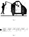
- the vehicle (V) is shown with, under the chassis, a capacitive connection symbolizing the electrical capacity C v formed by the vehicle relative to the ground.
- the user (B) is also represented with a symbolic capacitive link C b relative to the ground.
- the plate (1) forming the electric charge sensor also has a capacitive connection C s with the metal structure of the vehicle.
- an electronic processing circuit (2) connected to said wafer (1) processes the information coming from the capacities arranged at the input according to the coupling mentioned above, and reflects the variation of the capacity equivalent to the address of the electronic control unit of the vehicle, and in particular of the transceiver (not shown) linked to the latter.
- the processing circuit (2) transforms the measurement of input capacity into an electrical output signal in the form of a pulse of fixed duration.
- the objective of the invention is to detect a relative variation in the capacity, and not a variation between two predetermined values, which eliminates the problems linked to the influence of variations in external parameters, such as the temperature or the humidity, on the value of the “parasitic” capacity C s existing between the sensor (1) and the vehicle (V).
- this relative measure makes it possible not to worry the quality of the contact between the user's body and the door handle, contact which can be altered by the formation of dust on said handle, the existence of dirt on the hands handling the handle, etc ...
- the variation of input capacity of the circuit is transformed into a frequency variation by a high frequency oscillator (from 100 kHz to 2 MHz).
- the signal goes through a converter stage which converts it into a voltage to allow analog signal processing.
- a high-pass or differentiating filter removes on the floor depending on the component continuous voltage signal, which prevents taking into account variations in static capacity due to the environment.
- a voltage amplifier then increases the sensitivity of the detection.
- the gain of this amplifier stage is for example 10, but it can be expected higher than this figure.
- a threshold component of the monostable trigger type makes it possible to transform positive or negative variations of the signal into pulses square, creating a two-state logic signal. It should be noted that for each impulse, the rising edge corresponds to the contact of the hand on the handle of the door.
- Such a circuit makes it possible to avoid parasitic detections caused for example by said static variations in the capacity of the sensor: only the contacts on the handles are detected. It also allows to operate at low current, that is to say with a current lower than 2 mA for a power supply set at 5V.
- the detection offered by this system is very fast, since the delay between contact and electronic detection is of the order of a millisecond.
- the size of electronic components is further very reduced, and the assembly can be integrated to the handle of the vehicle door.
- the use of circuits in MOS or HCMOS finally leads to inexpensive manufacturing.
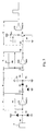
- Figures 4 and 5 relate to the capacity / frequency converter.
- the detection plate (1) is connected to the input of the capacity / converter frequency.
- This converter uses the basic principle of a gate oscillator CMOS with hysteresis. This choice is advantageous in terms of cost and availability of this type of component in the HCMOS series: a circuit referenced 74 HC 14 could for example be used.
- the CMOS logic gate (U1A) is a hysteresis logic inverter.
- the resistance (R2) which connects the input to the output acts on the reaction of the oscillator, such so that the more this resistance (R2) decreases, the more the output frequency increases, and conversely when it increases, the frequency decreases.
- the other element of this oscillator is of course the detection plate (1) whose capacity in relation to mass depends both on the environment and on proximity to the human body.
- the capacitive plate (1) charges through the resistor (R2) until the door input voltage exceeds the upper hysteresis threshold of tilting.
- the output goes low and the reverse phenomenon occurs: the plate (1) discharges through the resistor (R2) until the door input voltage is less than the basic hysteresis threshold, and the door returns to the high state.
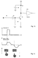
- the exit of the door (U1A) there is a square signal (see Figure 5) whose frequency depends on the capacity of the plate (1). The frequency variation is linear as a function of said capacity.
- the value of the resistance (R2) is determined experimentally to obtain a frequency greater than 100 kHz when the human body does not touch the detection plate.
- the supply current consumed by this oscillator strongly depends on the frequency: a compromise on the choice of resistance (R2) reduces the total current of the circuit to less than 1 mA.
- the diodes (D1, D2) and the resistor (R1) protect the entrance of the door logic (U1A), especially against overvoltages and discharges always possible.
- the frequency / voltage converter is shown in Figure 6.
- the principle of this converter is based on the variation of impedance of a capacitor (C1) as a function of frequency.
- the diodes (D4) and (D3) and the capacitor (C2) in fact constitute a rectifier which, associated with the capacity (C1), performs the frequency conversion function into voltage. If the frequency decreases, the capacitance impedance (C1) increases.
- the dynamic resistance of the diodes actually forms a voltage divider with the capacitance impedance (C1), which causes a decrease in the voltage straightened.
- the capacitor (C2) associated with the resistor (R3) finally filters the voltage rectified with a time constant of 100 ⁇ s, to ensure detection fast, that is to say in the millisecond that follows the contact of the hand against the detection plate (1).
- a high-pass filter eliminates variations in DC voltage at the output of the rectifier.
- This filter consists of the capacity (C3), associated with the resistor (R4), which determines the input impedance of the amplifier (U2A).
- the ratio of (R4) to (R3) must be at least 5, and preferably at around 10, so as not to influence the filtering stage consisting of the resistance (R3) and capacity (C2) located upstream.
- the time constant of the resistance (R4) multiplied by the value of the capacitance impedance (C3) is close to 100 ms. It acts on the speed of triggering of the sensor when the hand approaches the detection plate. The greater the time constant, the more sensitive the sensor is to slow hand variations.
- the amplifier is one of the fundamental links of the circuit: it brings a gain voltage stable in temperature and requires only a small current power supply, of the order of 100 ⁇ A.
- the logic gate (U2A) is a gate inverting type 4069 not "buffered” (which does not include a output power).
- This door (U2A) associated with the resistance (R5) determines the quiescent point of the output voltage at half the voltage feed.
- the capacitance (C4) decreases the gain at high frequencies in order to reduce the rapid transient disturbances and frequency residuals from the oscillator.
- the cutoff frequency is determined by the time constant calculated from the impedance of the capacitance (C4) and the resistance (R4). This frequency corresponds to approximately 1000 Hz and ensures a response time of the detector less than a millisecond.
- the shape of the amplifier output signal (U2A) is shown in Figure 9. This signal shows a positive voltage pulse when we approach the hand of the detector plate (1), and a negative pulse when you move your hand away.
- the monostable trigger is shown in Figure 10. It allows obtaining a pulse of fixed duration when the hand comes into contact with the plate detector (1).
- This trigger consists of a transistor (Q1) associated with the capacity (C5).
- a positive pulse from the amplifier (U2A) charges the capacitance (C5) through the resistor (R6) which has the function of limiting the current charge.
- the latter crosses the base-emitter junction of the transistor (Q1) and makes it busy.
- the voltage at the collector of the transistor (Q1) goes to zero volts during the base-emitter voltage is greater than approximately 0.6 V.
- the duration of the output pulse depends on the value of the resistance (R6) and the value of the capacity (C5).
- the resistor (R7) is actually used to charge the capacitor (C5) on the negative parts of the pulses delivered by the amplifier (U2A).
- the capacitor (C6) decouples the power supply.
- the CMOS logic gate (U1D) is a hysteresis logic inverter which forms the pulse of the transistor (Q1) at a level compatible with the circuits logic that use this sensor.
- U1D CMOS logic gate
Landscapes
- Engineering & Computer Science (AREA)
- Mechanical Engineering (AREA)
- Electronic Switches (AREA)
- Lock And Its Accessories (AREA)
Abstract
- un oscillateur convertisseur (A) des variations de capacité en variations de fréquence ;
- un convertisseur (B) convertissant les variations de fréquences en variations de tension ;
- un filtre passe-haut (C) ou différentiateur ;
- un amplificateur de tension (D) ; et
- un déclencheur monostable (E) produisant un signal de sortie sous forme d'impulsions.
Description
- un oscillateur convertisseur des variations de capacité en variations de fréquence ;
- un convertisseur convertissant les variations de fréquence en variations de tension ;
- un filtre passe-haut ou différentiateur ;
- un amplificateur de tension ; et
- un déclencheur monostable produisant un signal de sortie sous forme d'impulsions.
- Cv = capacité du véhicule ;
- Cb = capacité du corps humain ; et
- Cs = capacité "parasite" du capteur par rapport à la structure du véhicule.
- la figure 1 représente un schéma équivalent du principe de l'invention ;
- la figure 2 montre un schéma bloc du circuit ;
- la figure 3 donne un exemple de circuit électronique de traitement ;
- la figure 4 représente l'étage oscillateur ;
- la figure 5 donne la forme des signaux d'entrée et de sortie de l'oscillateur en fonction du temps ;
- la figure 6 illustre une possibilité de circuit pour un étage convertisseur fréquence / tension ;
- la figure 7 montre la forme du signal aux bornes de la capacité de sortie de cet étage ;
- la figure 8 représente le filtre passe-haut et l'amplificateur ;
- la figure 9 donne la forme du signal en sortie dudit amplificateur ;
- la figure 10 illustre un circuit déclencheur monostable possible ; et
- la figure 11 montre la forme des signaux en sortie de l'étage de la figure 10, et la forme de la tension base-émetteur.
- Le convertisseur est fréquence est référencé A ;
- L'étage de transformation en un signal variable en tension apparaít en B ;
- Le filtre passe-haut porte la référence C ;
- L'amplificateur de tension est signalé par D ; et
- Le déclencheur monostable de sortie est référencé E.
Claims (16)
- Dispositif de commutation fonctionnant par simple contact d'un corps humain, comportant un capteur capacitif (1) reflétant l'existence dudit contact, connecté à un circuit électronique de traitement (2) de la variation d'une grandeur électrique affectant ledit capteur (1), caractérisé en ce que le circuit de traitement (2) comporte successivement les étages suivants :un oscillateur convertisseur (A) des variations de capacité en variations de fréquence ;un convertisseur (B) convertissant les variations de fréquences en variations de tension ;un filtre passe-haut (C) ou différentiateur ;un amplificateur de tension (D) ; etun déclencheur monostable (E) produisant un signal de sortie sous forme d'impulsions.
- Dispositif de commutation selon la revendication précédente, caractérisé en ce que ledit capteur capacitif consiste en une plaquette métallique (1) disposée sur une structure capacitive dotée d'éléments pilotables par commutation.
- Dispositif de commutation selon la revendication précédente, caractérisé en ce que la plaquette métallique (1) est isolée de ladite structure capacitive par une couche isolante d'épaisseur non négligeable, permettant de maintenir la capacité de la plaquette (1) par rapport à la structure à une valeur minimale.
- Dispositif de commutation selon l'une des revendications 1 à 3, caractérisé en ce que l'oscillateur convertisseur (A) de capacité en fréquence est basé sur un inverseur logique (U1A) à hystérésis dont l'entrée et la sortie sont reliés par une résistance (R2) de réglage de la fréquence.
- Dispositif de commutation selon la revendication précédente, caractérisé en ce que l'entrée de l'inverseur (U1A) et le capteur capacitif (1) sont reliés via une résistance (R1), ladite entrée étant en outre reliée à la tension d'alimentation (VDD) et à la masse (G) via deux diodes de protection.
- Dispositif de commutation selon l'une des revendications 3 à 5, caractérisé en ce que le convertisseur (B) fréquence / tension est constitué d'une première capacité (C1) de liaison, couplé à un redresseur comportant deux diodes (D3, D4) et une capacité (C2) de filtrage.
- Dispositif de commutation selon la revendication précédente, caractérisé en ce qu'une résistance (R3) est disposée en parallèle à la capacité (C2).
- Dispositif de commutation selon l'une quelconque des revendications 3 à 7, caractérisé en ce que le filtre passe-haut (C) est constitué d'une capacité (C3) connectée en série à une résistance (R4).
- Dispositif de commutation selon la revendication précédente, caractérisé en ce que le rapport entre (R4) et (R3) est supérieur à 5.
- Dispositif de commutation selon l'une quelconque des revendications 3 à 9, caractérisé en ce que l'amplificateur de tension (D) comporte une porte inverseuse (U2A) associée à une boucle de contre-réaction constituée d'une résistance (R5) et d'une capacité (C4) en parallèle.
- Dispositif de commutation selon la revendication précédente, caractérisé en ce que le déclencheur monostable (E) est constitué d'un transistor (Q1) dont la base est connectée à une capacité (C5), et le collecteur est relié à un inverseur logique à hystérésis (U1D).
- Dispositif de commutation selon la revendication précédente, caractérisé en ce que la sortie de l'amplificateur de tension (D) est reliée à la capacité (C5) via une résistance (R6).
- Dispositif de commutation selon l'une des revendications 11 et 12, caractérisé en ce qu'une résistance (R7) est disposée en sortie de la capacité (C5), en parallèle à la jonction base-émetteur du transistor (Q1).
- Dispositif de commutation selon l'une quelconque des revendications précédentes appliqué au verrouillage / déverrouillage d'au moins une des portes d'un véhicule (V).
- Dispositif de commutation selon la revendication précédente, caractérisé en ce que le capteur (1) est constitué d'une plaquette métallique fixée au véhicule (V) au voisinage d'au moins un des mécanismes d'ouverture des portes.
- Dispositif de commutation selon l'une des revendications 14 et 15, caractérisé en ce que le circuit électronique de traitement est connecté à un émetteur-récepteur lié au véhicule (V), émettant dès détection du contact un signal radiofréquence à destination d'un transpondeur manuel comportant un émetteur-récepteur, ledit transpondeur renvoyant à réception un signal d'identification autorisant la commande du système électronique de verrouillage / déverrouillage central des portes du véhicule (V).
Applications Claiming Priority (4)
| Application Number | Priority Date | Filing Date | Title |
|---|---|---|---|
| FR0007098 | 2000-06-02 | ||
| FR0007098A FR2809759B1 (fr) | 2000-06-02 | 2000-06-02 | Dispositif de verrouillage automatise des acces a un vehicule automobile |
| FR0014210 | 2000-11-06 | ||
| FR0014210A FR2809885B1 (fr) | 2000-06-02 | 2000-11-06 | Dispositif de commutation fonctionnant par contact d'un corps humain |
Publications (2)
| Publication Number | Publication Date |
|---|---|
| EP1160400A1 true EP1160400A1 (fr) | 2001-12-05 |
| EP1160400B1 EP1160400B1 (fr) | 2005-03-02 |
Family
ID=26212444
Family Applications (1)
| Application Number | Title | Priority Date | Filing Date |
|---|---|---|---|
| EP20010440153 Expired - Lifetime EP1160400B1 (fr) | 2000-06-02 | 2001-06-01 | Dispositif de commutation fonctionnant par contact d'un corps humain |
Country Status (3)
| Country | Link |
|---|---|
| EP (1) | EP1160400B1 (fr) |
| DE (1) | DE60109088T2 (fr) |
| FR (1) | FR2809885B1 (fr) |
Cited By (11)
| Publication number | Priority date | Publication date | Assignee | Title |
|---|---|---|---|---|
| FR2834813A1 (fr) * | 2002-01-16 | 2003-07-18 | Simu | Dispositif securise de programmation et de controle de l'ouverture d'un moyen de protection d'une zone ou d'un batiment protege |
| DE10315845A1 (de) * | 2003-04-08 | 2004-11-04 | Richter, Wolfgang | System, Systemkomponenten und Verfahren zur Abwicklung eines hermetisch validierbaren Datentransfers |
| WO2007045703A1 (fr) * | 2005-10-14 | 2007-04-26 | Modulos Digitales Para El Lavado S.A. | Element de detection destine a un dispositif d'ecran tactile sensoriel |
| WO2009110814A3 (fr) * | 2008-03-04 | 2009-12-10 | Boban Stojanovic | Capteur vertical |
| US8346467B2 (en) | 2006-05-18 | 2013-01-01 | Continental Automotive France | Device for detecting an event in a vehicle or in the surrounds of a vehicle |
| WO2013004603A3 (fr) * | 2011-07-01 | 2013-04-11 | Microchip Technology Germany Ii Gmbh & Co. Kg | Procédé et dispositif d'évaluation pour un capteur à contact capacitif |
| EP2653355A1 (fr) * | 2012-04-18 | 2013-10-23 | Eileo | Ensemble clavier et procédé pour accéder à une voiture |
| CN104270134A (zh) * | 2014-09-03 | 2015-01-07 | 华南理工大学 | 一种反应快捷可靠的触摸开关电路 |
| CN107643440A (zh) * | 2017-11-08 | 2018-01-30 | 湖南省湘电试验研究院有限公司 | 一种人体工频感应电流的检测装置及其应用方法 |
| CN108216027A (zh) * | 2018-01-17 | 2018-06-29 | 重庆交通大学 | 乘客开门下车防撞预警系统 |
| US10290411B2 (en) | 2005-03-30 | 2019-05-14 | Strattec Security Corporation | Residual magnetic devices and methods |
Families Citing this family (6)
| Publication number | Priority date | Publication date | Assignee | Title |
|---|---|---|---|---|
| ATE411205T1 (de) | 2002-08-15 | 2008-10-15 | Ident Technology Ag | Schaltungsanordnung zur selektiven schaltsignalgenerierung |
| DE102004044376A1 (de) * | 2004-09-10 | 2006-03-30 | Daimlerchrysler Ag | Vorrichtung zum Ver- und/oder Entriegeln einer Fahrzeugtür mit einem elektronischen Zugangsberechtigungssystem |
| US7969705B2 (en) | 2005-03-30 | 2011-06-28 | Strattec Security Corporation | Residual magnetic devices and methods |
| US7401483B2 (en) | 2005-03-30 | 2008-07-22 | Strattec Security Corporation | Residual magnetic devices and methods for an ignition actuation blockage device |
| EP2683084B1 (fr) | 2012-07-06 | 2015-11-18 | abatec group AG | Sécurité contre le vol pour poids lourd au moyen d'une ficelle douanière |
| DE102014205063B4 (de) * | 2014-03-19 | 2022-11-17 | Bayerische Motoren Werke Aktiengesellschaft | Verfahren und eine Vorrichtung zur automatisierten Bestimmung eines durch einen mechanischen Kontakt mit einem Fremdkörper bedingten Schadens an einem Fahrzeug |
Citations (8)
| Publication number | Priority date | Publication date | Assignee | Title |
|---|---|---|---|---|
| FR2271538A1 (en) * | 1973-12-27 | 1975-12-12 | Cii | Capacitive proximity detector or switch - detects effective capacitance of object and activates logic circuit |
| US4758735A (en) * | 1986-09-29 | 1988-07-19 | Nartron Corporation | DC touch control switch circuit |
| US4891627A (en) * | 1983-11-22 | 1990-01-02 | Honda Giken Kogyo Kabushiki Kaisha | Device for detecting object |
| DE4132036A1 (de) * | 1991-09-26 | 1993-04-01 | Schmitt Klaus Peter | Elektrische steuervorrichtung fuer ton- oder lichtsignale |
| WO1997041322A1 (fr) * | 1996-04-27 | 1997-11-06 | Huf Hülsbeck & Fürst Gmbh. & Co. Kg. | Systeme de fermeture, notamment pour automobiles |
| FR2771534A1 (fr) * | 1997-11-24 | 1999-05-28 | Valeo Systemes De Fermetures | Vehicule automobile equipe d'un systeme de detection de l'approche d'un utilisateur |
| EP0955431A1 (fr) * | 1998-05-05 | 1999-11-10 | Valeo Securite Habitacle | Système de sécurité pour un ouvrant de véhicule automobile |
| FR2785703A1 (fr) * | 1998-11-06 | 2000-05-12 | Valeo Securite Habitacle | Dispositif pour detecter la presence d'un individu et systeme de deverrouillage d'ouvrant(s) de vehicule, notamment automobile, comportant un tel dispositif |
-
2000
- 2000-11-06 FR FR0014210A patent/FR2809885B1/fr not_active Expired - Fee Related
-
2001
- 2001-06-01 DE DE2001609088 patent/DE60109088T2/de not_active Expired - Lifetime
- 2001-06-01 EP EP20010440153 patent/EP1160400B1/fr not_active Expired - Lifetime
Patent Citations (8)
| Publication number | Priority date | Publication date | Assignee | Title |
|---|---|---|---|---|
| FR2271538A1 (en) * | 1973-12-27 | 1975-12-12 | Cii | Capacitive proximity detector or switch - detects effective capacitance of object and activates logic circuit |
| US4891627A (en) * | 1983-11-22 | 1990-01-02 | Honda Giken Kogyo Kabushiki Kaisha | Device for detecting object |
| US4758735A (en) * | 1986-09-29 | 1988-07-19 | Nartron Corporation | DC touch control switch circuit |
| DE4132036A1 (de) * | 1991-09-26 | 1993-04-01 | Schmitt Klaus Peter | Elektrische steuervorrichtung fuer ton- oder lichtsignale |
| WO1997041322A1 (fr) * | 1996-04-27 | 1997-11-06 | Huf Hülsbeck & Fürst Gmbh. & Co. Kg. | Systeme de fermeture, notamment pour automobiles |
| FR2771534A1 (fr) * | 1997-11-24 | 1999-05-28 | Valeo Systemes De Fermetures | Vehicule automobile equipe d'un systeme de detection de l'approche d'un utilisateur |
| EP0955431A1 (fr) * | 1998-05-05 | 1999-11-10 | Valeo Securite Habitacle | Système de sécurité pour un ouvrant de véhicule automobile |
| FR2785703A1 (fr) * | 1998-11-06 | 2000-05-12 | Valeo Securite Habitacle | Dispositif pour detecter la presence d'un individu et systeme de deverrouillage d'ouvrant(s) de vehicule, notamment automobile, comportant un tel dispositif |
Cited By (16)
| Publication number | Priority date | Publication date | Assignee | Title |
|---|---|---|---|---|
| FR2834813A1 (fr) * | 2002-01-16 | 2003-07-18 | Simu | Dispositif securise de programmation et de controle de l'ouverture d'un moyen de protection d'une zone ou d'un batiment protege |
| DE10315845A1 (de) * | 2003-04-08 | 2004-11-04 | Richter, Wolfgang | System, Systemkomponenten und Verfahren zur Abwicklung eines hermetisch validierbaren Datentransfers |
| DE10315845B4 (de) * | 2003-04-08 | 2005-10-06 | Wolfgang Richter | System, Systemkomponenten und Verfahren zur Abwicklung eines hermetisch validierbaren Datentransfers |
| US10290411B2 (en) | 2005-03-30 | 2019-05-14 | Strattec Security Corporation | Residual magnetic devices and methods |
| WO2007045703A1 (fr) * | 2005-10-14 | 2007-04-26 | Modulos Digitales Para El Lavado S.A. | Element de detection destine a un dispositif d'ecran tactile sensoriel |
| US8346467B2 (en) | 2006-05-18 | 2013-01-01 | Continental Automotive France | Device for detecting an event in a vehicle or in the surrounds of a vehicle |
| WO2009110814A3 (fr) * | 2008-03-04 | 2009-12-10 | Boban Stojanovic | Capteur vertical |
| US9753070B2 (en) | 2011-07-01 | 2017-09-05 | Microchip Technology Incorporated | Evaluation method and evaluation device for a capacitive contact sensor |
| WO2013004603A3 (fr) * | 2011-07-01 | 2013-04-11 | Microchip Technology Germany Ii Gmbh & Co. Kg | Procédé et dispositif d'évaluation pour un capteur à contact capacitif |
| KR20140053134A (ko) * | 2011-07-01 | 2014-05-07 | 마이크로칩 테크놀로지 저머니 Ⅱ 게엠베하 운트 콤파니 카게 | 용량성 접촉 센서를 위한 평가 방법 및 평가 장치 |
| WO2013156353A1 (fr) * | 2012-04-18 | 2013-10-24 | Eileo | Ensemble clavier et procédé d'accès à une voiture |
| EP2653355A1 (fr) * | 2012-04-18 | 2013-10-23 | Eileo | Ensemble clavier et procédé pour accéder à une voiture |
| CN104270134A (zh) * | 2014-09-03 | 2015-01-07 | 华南理工大学 | 一种反应快捷可靠的触摸开关电路 |
| CN107643440A (zh) * | 2017-11-08 | 2018-01-30 | 湖南省湘电试验研究院有限公司 | 一种人体工频感应电流的检测装置及其应用方法 |
| CN107643440B (zh) * | 2017-11-08 | 2024-01-09 | 湖南省湘电试验研究院有限公司 | 一种人体工频感应电流的检测装置及其应用方法 |
| CN108216027A (zh) * | 2018-01-17 | 2018-06-29 | 重庆交通大学 | 乘客开门下车防撞预警系统 |
Also Published As
| Publication number | Publication date |
|---|---|
| DE60109088T2 (de) | 2006-04-13 |
| FR2809885A1 (fr) | 2001-12-07 |
| EP1160400B1 (fr) | 2005-03-02 |
| DE60109088D1 (de) | 2005-04-07 |
| FR2809885B1 (fr) | 2003-01-17 |
Similar Documents
| Publication | Publication Date | Title |
|---|---|---|
| EP1160400B1 (fr) | Dispositif de commutation fonctionnant par contact d'un corps humain | |
| EP0918309B1 (fr) | Système de verrouillage pour véhicule automobile équipé d'un système de détection de l'approche d'un utilisateur | |
| FR3047808B1 (fr) | Procede de detection d'approche et/ou de contact d'une main d'un utilisateur vers une poignee de portiere de vehicule et dispositif de detection associe | |
| EP1001117B1 (fr) | Système pour sécuriser une transmission bidirectionnelle de données pour l'accès a un espace clos, en particulier pour l'accès a un véhicule | |
| EP0596805A1 (fr) | Système pour commander à distance le verrouillage et le déverrouillage des portes et des ouvrants d'un habitacle notamment d'un véhicule automobile | |
| FR2606163A1 (fr) | Procede de detection sans contact de corps parcourus par des courants de foucault, en particulier d'objets metalliques, ainsi que les detecteurs qui s'appuient sur le procede | |
| EP0522949A1 (fr) | Détecteur de proximité | |
| EP1301898A1 (fr) | Transpondeur passif a faible consommation | |
| EP2652719B1 (fr) | Module electronique de communication pour le verrouillage/deverrouillage d'un ouvrant de vehicule automobile, unite centrale de commande associee et systeme d'acces mains-libres | |
| EP0062572A2 (fr) | Clavier capacitif à structure antiparasite | |
| FR2571908A1 (fr) | Dispositif commutateur de proximite | |
| FR3063097A1 (fr) | Procede de determination de contacts parasites sur un capteur de detection d'approche et/ou de contact et dispositif de determination associe | |
| FR3006793A1 (fr) | Dispositif, capteur et procede de detection de la presence d'un utilisateur pour l'ouverture d'un acces a un vehicule automobile | |
| FR2921958A1 (fr) | Dispositif de detection de presence d'un utilisateur par un vehicule | |
| EP1423917B1 (fr) | Capteur de presence | |
| FR2809759A1 (fr) | Dispositif de verrouillage automatise des acces a un vehicule automobile | |
| EP0955431A1 (fr) | Système de sécurité pour un ouvrant de véhicule automobile | |
| FR2828286A1 (fr) | Dispositif de diagnostic pour une antenne | |
| FR2809132A1 (fr) | Vehicule automobile equipe d'un systeme de detection de presence d'utilisateur | |
| WO2020048764A1 (fr) | Dispositif et procédé de détection d'intention de verrouillage ou de déverrouillage d'un ouvrant de véhicule automobile | |
| FR2606162A1 (fr) | Capteur de proximite et son application a la teledetection | |
| EP2907237B1 (fr) | Recipient pour le stockage d'un fluide destine a interagir avec un utilisateur | |
| FR2998235A1 (fr) | Dispositif de detection d'un badge d'acces « main libre » autour d'un vehicule et de detection de presence d'un utilisateur a proximite d'un ouvrant d'un vehicule et procede de detection associe | |
| FR2785703A1 (fr) | Dispositif pour detecter la presence d'un individu et systeme de deverrouillage d'ouvrant(s) de vehicule, notamment automobile, comportant un tel dispositif | |
| WO2016156684A1 (fr) | Dispositif et procede de detection capacitive et interface utilisateur |
Legal Events
| Date | Code | Title | Description |
|---|---|---|---|
| PUAI | Public reference made under article 153(3) epc to a published international application that has entered the european phase |
Free format text: ORIGINAL CODE: 0009012 |
|
| AK | Designated contracting states |
Kind code of ref document: A1 Designated state(s): DE ES FR GB IT SE Kind code of ref document: A1 Designated state(s): AT BE CH CY DE DK ES FI FR GB GR IE IT LI LU MC NL PT SE TR |
|
| AX | Request for extension of the european patent |
Free format text: AL;LT;LV;MK;RO;SI |
|
| 17P | Request for examination filed |
Effective date: 20020510 |
|
| AKX | Designation fees paid |
Free format text: DE ES FR GB IT SE |
|
| GRAP | Despatch of communication of intention to grant a patent |
Free format text: ORIGINAL CODE: EPIDOSNIGR1 |
|
| GRAS | Grant fee paid |
Free format text: ORIGINAL CODE: EPIDOSNIGR3 |
|
| GRAA | (expected) grant |
Free format text: ORIGINAL CODE: 0009210 |
|
| AK | Designated contracting states |
Kind code of ref document: B1 Designated state(s): DE ES FR GB IT SE |
|
| PG25 | Lapsed in a contracting state [announced via postgrant information from national office to epo] |
Ref country code: IT Free format text: LAPSE BECAUSE OF FAILURE TO SUBMIT A TRANSLATION OF THE DESCRIPTION OR TO PAY THE FEE WITHIN THE PRESCRIBED TIME-LIMIT;WARNING: LAPSES OF ITALIAN PATENTS WITH EFFECTIVE DATE BEFORE 2007 MAY HAVE OCCURRED AT ANY TIME BEFORE 2007. THE CORRECT EFFECTIVE DATE MAY BE DIFFERENT FROM THE ONE RECORDED. Effective date: 20050302 Ref country code: GB Free format text: LAPSE BECAUSE OF FAILURE TO SUBMIT A TRANSLATION OF THE DESCRIPTION OR TO PAY THE FEE WITHIN THE PRESCRIBED TIME-LIMIT Effective date: 20050302 Ref country code: ES Free format text: LAPSE BECAUSE OF FAILURE TO SUBMIT A TRANSLATION OF THE DESCRIPTION OR TO PAY THE FEE WITHIN THE PRESCRIBED TIME-LIMIT Effective date: 20050302 |
|
| REG | Reference to a national code |
Ref country code: GB Ref legal event code: FG4D Free format text: NOT ENGLISH |
|
| REG | Reference to a national code |
Ref country code: IE Ref legal event code: FG4D Free format text: FRENCH |
|
| REF | Corresponds to: |
Ref document number: 60109088 Country of ref document: DE Date of ref document: 20050407 Kind code of ref document: P |
|
| GBV | Gb: ep patent (uk) treated as always having been void in accordance with gb section 77(7)/1977 [no translation filed] |
Effective date: 20050302 |
|
| PLBE | No opposition filed within time limit |
Free format text: ORIGINAL CODE: 0009261 |
|
| STAA | Information on the status of an ep patent application or granted ep patent |
Free format text: STATUS: NO OPPOSITION FILED WITHIN TIME LIMIT |
|
| 26N | No opposition filed |
Effective date: 20051205 |
|
| PG25 | Lapsed in a contracting state [announced via postgrant information from national office to epo] |
Ref country code: SE Free format text: LAPSE BECAUSE OF FAILURE TO SUBMIT A TRANSLATION OF THE DESCRIPTION OR TO PAY THE FEE WITHIN THE PRESCRIBED TIME-LIMIT Effective date: 20050602 |
|
| REG | Reference to a national code |
Ref country code: FR Ref legal event code: PLFP Year of fee payment: 16 |
|
| REG | Reference to a national code |
Ref country code: FR Ref legal event code: PLFP Year of fee payment: 17 |
|
| REG | Reference to a national code |
Ref country code: FR Ref legal event code: PLFP Year of fee payment: 18 |
|
| REG | Reference to a national code |
Ref country code: DE Ref legal event code: R082 Ref document number: 60109088 Country of ref document: DE Ref country code: DE Ref legal event code: R081 Ref document number: 60109088 Country of ref document: DE Owner name: APTIV TECHNOLOGIES LIMITED, BB Free format text: FORMER OWNER: DELPHI TECHNOLOGIES, INC., TROY, MICH., US |
|
| PGFP | Annual fee paid to national office [announced via postgrant information from national office to epo] |
Ref country code: FR Payment date: 20190625 Year of fee payment: 19 |
|
| PGFP | Annual fee paid to national office [announced via postgrant information from national office to epo] |
Ref country code: DE Payment date: 20200622 Year of fee payment: 20 |
|
| PG25 | Lapsed in a contracting state [announced via postgrant information from national office to epo] |
Ref country code: FR Free format text: LAPSE BECAUSE OF NON-PAYMENT OF DUE FEES Effective date: 20200630 |
|
| REG | Reference to a national code |
Ref country code: DE Ref legal event code: R071 Ref document number: 60109088 Country of ref document: DE |