EP1159905B1 - Verfahren zum Sichern von Artikeln und durch ein solches Verfahren hergestellter elektrischer Wasserkocher - Google Patents
Verfahren zum Sichern von Artikeln und durch ein solches Verfahren hergestellter elektrischer Wasserkocher Download PDFInfo
- Publication number
- EP1159905B1 EP1159905B1 EP01302076A EP01302076A EP1159905B1 EP 1159905 B1 EP1159905 B1 EP 1159905B1 EP 01302076 A EP01302076 A EP 01302076A EP 01302076 A EP01302076 A EP 01302076A EP 1159905 B1 EP1159905 B1 EP 1159905B1
- Authority
- EP
- European Patent Office
- Prior art keywords
- further characterized
- water gauge
- sealing ring
- backing
- housing member
- Prior art date
- Legal status (The legal status is an assumption and is not a legal conclusion. Google has not performed a legal analysis and makes no representation as to the accuracy of the status listed.)
- Expired - Lifetime
Links
- 238000000034 method Methods 0.000 title claims abstract description 23
- XLYOFNOQVPJJNP-UHFFFAOYSA-N water Substances O XLYOFNOQVPJJNP-UHFFFAOYSA-N 0.000 claims abstract description 73
- 238000007789 sealing Methods 0.000 claims abstract description 44
- 238000003466 welding Methods 0.000 claims abstract description 16
- 229910001220 stainless steel Inorganic materials 0.000 claims abstract description 9
- 239000010935 stainless steel Substances 0.000 claims abstract description 9
- 229920000515 polycarbonate Polymers 0.000 claims abstract description 7
- 239000004417 polycarbonate Substances 0.000 claims abstract description 7
- 239000004743 Polypropylene Substances 0.000 claims abstract description 6
- 229920002379 silicone rubber Polymers 0.000 claims abstract description 5
- 229920003023 plastic Polymers 0.000 claims description 13
- 239000004033 plastic Substances 0.000 claims description 12
- 239000000463 material Substances 0.000 claims description 11
- 239000002184 metal Substances 0.000 claims description 9
- 229910052751 metal Inorganic materials 0.000 claims description 9
- -1 polypropylene Polymers 0.000 claims description 3
- 229920001155 polypropylene Polymers 0.000 claims description 3
- 229920000379 polypropylene carbonate Polymers 0.000 abstract description 3
- 230000001174 ascending effect Effects 0.000 description 6
- 229910000831 Steel Inorganic materials 0.000 description 3
- 238000010438 heat treatment Methods 0.000 description 3
- 239000010959 steel Substances 0.000 description 3
- XEEYBQQBJWHFJM-UHFFFAOYSA-N Iron Chemical compound [Fe] XEEYBQQBJWHFJM-UHFFFAOYSA-N 0.000 description 2
- 238000009835 boiling Methods 0.000 description 1
- 238000001816 cooling Methods 0.000 description 1
- 230000000694 effects Effects 0.000 description 1
- 238000003780 insertion Methods 0.000 description 1
- 230000037431 insertion Effects 0.000 description 1
- 238000007689 inspection Methods 0.000 description 1
- 229910052742 iron Inorganic materials 0.000 description 1
- 239000007788 liquid Substances 0.000 description 1
- 238000012856 packing Methods 0.000 description 1
- 238000005192 partition Methods 0.000 description 1
Images







Classifications
-
- A—HUMAN NECESSITIES
- A47—FURNITURE; DOMESTIC ARTICLES OR APPLIANCES; COFFEE MILLS; SPICE MILLS; SUCTION CLEANERS IN GENERAL
- A47J—KITCHEN EQUIPMENT; COFFEE MILLS; SPICE MILLS; APPARATUS FOR MAKING BEVERAGES
- A47J31/00—Apparatus for making beverages
- A47J31/44—Parts or details or accessories of beverage-making apparatus
- A47J31/4403—Constructional details
- A47J31/4457—Water-level indicators
-
- A—HUMAN NECESSITIES
- A47—FURNITURE; DOMESTIC ARTICLES OR APPLIANCES; COFFEE MILLS; SPICE MILLS; SUCTION CLEANERS IN GENERAL
- A47J—KITCHEN EQUIPMENT; COFFEE MILLS; SPICE MILLS; APPARATUS FOR MAKING BEVERAGES
- A47J27/00—Cooking-vessels
- A47J27/21—Water-boiling vessels, e.g. kettles
Definitions
- This invention relates to a method of securing a plurality of articles, and an electric kettle made by such a method. Such an invention relates more particularly to the provision of an electric kettle with a water gauge.
- German Utility Model Document No. DE 295 13 124 U1 discloses a kettle with a steel container and an ascending pipe made of a transparent and heat-proof plastic.
- the wall of the steel container is provided with a borehole at the lower end area of the ascending pipe, and in its upper area, in which a lower connecting pipe or an upper connecting pipe engages with the insertion of a heat-proof packing.
- Both connecting pipes are radially spaced apart from the ascending pipes, and mechanically rigidly link it with the container.
- the ascending pipe communicates with the inside of the container through the lower connecting pipe.
- the upper connecting pipe makes it possible to seal the upper end of the ascending pipe.
- the two connecting pipes are best moulded to the ascending pipe.
- British Patent Document No. GB 2 155 767 A which would form the basis for the two-part form of the independent claim hereto, discloses a water heating vessel having water level indicating means comprising a fixed member secured to a wall of the vessel to at least partially occupy an elongate opening in the wall.
- the fixed member comprises an elongate transparent or translucent partition opposite sides of which provide an external face, visible at the exterior of the vessel, and an internal face at least partially exposed to the interior of the vessel.
- the fixed member and the wall are constructed and arranged so that thermal effects, caused by heating of water in the vessel, can cause water to move vertically in contact with the internal face when the vessel contains at least a predetermined minimum quantity of water, to ensure that boiling of the water in the vessel will sterilize the indicator means.
- a method of securing a metal housing member with a water gauge made of a plastics material and a backing element made of a plastics material including fixedly securing said water gauge with said backing element, contacting and fixedly securing the housing member with said water gauge, and positioning a sealing member between and in contact with said housing member and said backing element, characterized in that said sealing member is in contact with said water gauge to thereby form a water-tight seal among said housing member, said backing element and said water gauge.
- an electric kettle including a metal housing member, a non-opaque water gauge and a backing member made of a plastics material, wherein said water gauge and said backing member are fixedly secured with each other, wherein said housing member contacts and is fixedly secured with said water gauge, and wherein a sealing member is positioned between and in contact with said housing member and said backing member, characterized in that said sealing member is in contact with said water gauge to thereby form a water-tight seal among said housing member, said backing member and said water gauge.
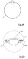
- the kettle 10 includes a lid releasably engageable with a stainless steel body 12 for containing liquid (e.g. water) to be boiled.
- a non-opaque (e.g. transparent) plastics water gauge 14 through which a user may inspect the level, and thus the amount, of water in the body 12.
- the water gauge 14 may include an index or scale for indicating the amount of water in the body 12 of the kettle 10.
- the water gauge 14 may be made of polypropylene or polycarbonate. In order to ensure that the engagement between the water gauge 14 and the body 12 is water-tight, six different arrangements are provided.
- the stainless steel body 12 is secured with both a first type of water gauge 14A, a first type of backing element 16A, and a first type of sealing ring 18A to form a water-tight seal.
- the backing element 16A may be made of polypropylene or polycarbonate. If both the water gauge 14A and the backing element 16A are made of polypropylene, they may be fixedly secured with each other by high-frequency welding or hot-plate welding. If both of them are made of polycarbonate, they may be fixedly secured with each other by high-frequency welding, hot-plate welding or ultra-sonic welding.
- the endless silicon rubber sealing ring 18A is positioned among and in contact with the housing 12, the water gauge 14A and the backing element 16A.
- the silicon rubber sealing ring 18A is circular in cross section.
- the backing element 16A includes a ridge 20A which is received within a channel 22A of the water gauge 14A.
- the sealing ring 18A is positioned among and in contact with the housing 12, the water gauge 14A and the backing element 16A.
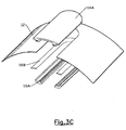
- Figs. 3A to 3C show a second arrangement according to the present invention, whereby the stainless steel body 12 is fixedly secured with both the first type of water gauge 14A and the first type of backing element 16A, to form a water-tight seal.
- the main difference in this arrangement is a sealing ring 18B.
- This sealing ring 18B is elongate in cross section with two flat surfaces. It can be seen in Fig. 3B that one flat surface abuts an inner surface of the steel body 12, while another flat surface abuts the backing element 16A.
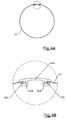
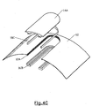
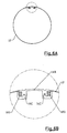
- Figs. 4A to 4C show a third arrangement according to the present invention, whereby the stainless steel body 12 is fixedly secured with the first type of water gauge 14A, a second type of backing element 16B and a third type of sealing ring 18C, to form a water-tight seal.
- the portion of the body 12 to be engaged with the backing element 16B is bent.
- This bent portion 12A is received within a cavity between the water gauge 14A, the backing element 16A and the sealing ring 18C.
- the sealing ring 18C is substantially rectangular in cross-section, and is in contact with the water gauge 14A, the backing element 16A and the bent portion 12A of the body 12.
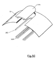
- Fig. 5A to 5C show an arrangement not according to the present invention; whereby the stainless steel body 12 is fixedly secured with the first type of water gauge 14A, the second type of backing element 16B and the sealing ring 18C, to form a water-tight seal.
- the sealing ring 18C is in contact with the outer surface of the body 12, the water gauge 14A and the backing element 16B, whereas in the arrangement shown in Fig. 5A to 5C, the sealing ring 18C is in contact with the inner surface of the body 12 and the backing element 16B, but is out of contact with the water gauge 14A.
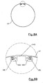
- Fig. 6A to 6C show another arrangement not according to the present invention, whereby the stainless steel body 12 is fixedly secured with a second type of water gauge 14B, a third type of backing element 16C and a fourth type of sealing ring 18D, to form a water-tight seal.
- the body 12 includes a stepped portion 12B, which is engaged with, and is received within a cavity among, the water gauge 14B, the backing element 16C and the sealing ring 18D.
- a recess 24 is formed on the outer surface of the water gauge 14B.
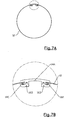
- Figs. 7A to 7C such show a fourth arrangement according to the present invention, whereby the housing 12 is fixedly secured with the first type of water gauge 14A, a fourth type of backing element 16D and a fifth type of sealing ring 18E, to form a water-tight seal.
- the sealing ring 18E includes two arms and is of a substantially U-shaped cross section. The bent portion 12A of the housing 12 is received within the cavity between the arms of the sealing ring 18E.
- Figs. 8A to 8C show a fifth arrangement according to the present invention, whereby the housing 12 is fixedly secured with the second type of water gauge 14B, the fourth type of backing element 16D, and the fifth type of sealing ring 18E, to form a water-tight seal.
- the housing 12 includes a stepped portion 12B, which is received within the cavity between the arms of the sealing ring 18E.
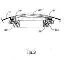
- FIG. 9 shows a sixth arrangement according to the present invention, whereby the housing 12 is fixedly secured with a third type of water gauge 14C, a fifth type of backing element 16E, and a sixth type of sealing ring 18F, to form a water-tight seal.
- the sealing ring 18F is also substantially U-shaped in cross-section, and receives a bent portion of the housing 12 sidewardly.
- an iron wire ring 28 is positioned between the water gauge 14C and the backing element 16E.
Landscapes
- Engineering & Computer Science (AREA)
- Food Science & Technology (AREA)
- Cookers (AREA)
- Discharge Heating (AREA)
- Casings For Electric Apparatus (AREA)
Claims (30)
- Verfahren zum Sichern eines Metallgehäusebauteils (12) mit einem Wasserpegel (14), hergestellt aus einem Kunststoffinaterial, und einem Rückenelement (16A, 16B, 16D, 16E), hergestellt aus einem Kunststoffmaterial, einschließend ein festes Sichern des Wasserpegels mit dem Rückenelement, ein Kontaktieren und festes Sichern des Gehäusebauteils mit dem Wasserpegel, und ein Positionieren eines Versiegelungsbauteils (18A, 18B, 18C, 18E, 18F) zwischen und in Kontakt mit dem Gehäusebauteil und dem Rückenelement, dadurch gekennzeichnet, daß das Versiegelungsbauteil in Kontakt mit dem Wasserpegel ist, um dadurch eine wasserdichte Versiegelung zwischen dem Gehäusebauteil, dem Rückenelement und dem Wasserpegel zu bilden.
- Verfahren nach Anspruch 1, weiter dadurch gekennzeichnet, daß das Versiegelungsbauteil einen endlosen Silikonkautschukversiegelungsring (18A, 18B, 18C, 18E, 18F) einschließt.
- Verfahren nach Anspruch 1 oder 2, weiter dadurch gekennzeichnet, daß das Metall rostfreier Stahl ist.
- Verfahren nach einem der vorangehenden Ansprüche, weiter dadurch gekennzeichnet, daß das Kunststoffmaterial Polypropylen ist.
- Verfahren nach Anspruch 4, weiter dadurch gekennzeichnet, daß der Wasserpegel und das Rückenelement fest miteinander gesichert sind durch Hochfrequenzverschweißen oder Heißplattenverschweißen.
- Verfahren nach einem der Ansprüche 1 bis 3, weiter dadurch gekennzeichnet, daß das Kunststoffmaterial Polycarbonat ist.
- Verfahren nach Anspruch 6, weiter dadurch gekennzeichnet, daß der Wasserpegel und das Rückenelement miteinander fest gesichert sind durch Hochfrequenzverschweißen, Heißplattenverschweißen oder Ultraschallverschweißen.
- Verfahren nach einem der vorangehenden Ansprüche, weiter gekennzeichnet durch ein Einschließen der Schritte eines Bildens wenigstens eines Kanalbauteils (22A) an dem Wasserpegel; eines Bildens wenigstens eines Rippenbauteils (20A) an dem Rückenelement; und eines Anordnens des Rippenbauteils des Rückenelements in dem Kanalbauteil des Wasserpegels.
- Verfahren nach einem der vorangehenden Ansprüche, weiter gekennzeichnet durch ein Einschließen der Schritte eines Bildens wenigstens eines gebogenen Bereichs (12A) an dem Gehäusebauteil; und eines Anordnens des gebogenen Bereichs des Gehäusebauteils innerhalb einer Aushöhlung, die zwischen dem Wasserpegel und dem Rückenelement gebildet wird.
- Verfahren nach einem der vorangehenden Ansprüche, weiter gekennzeichnet durch ein Einschließen der Schritte eines Bildens wenigstens eines abgestuften Bereichs (12B) an den Gehäuse; und eines Anordnens des abgestuften Bereichs des Gehäuses innerhalb einer Aushöhlung, die zwischen dem Wasserpegel und dem Rückenelement gebildet wird.
- Verfahren nach einem der Ansprüche 2 bis 10, weiter dadurch gekennzeichnet, daß der Versiegelungsring im wesentlichen im Querschnitt kreisförmig ist.
- Verfahren nach einem der Ansprüche 2 bis 10, weiter dadurch gekennzeichnet, daß der Versiegelungsring im wesentlichen im Querschnitt rechteckig ist.
- Verfahren nach einem der Ansprüche 2 bis 10, weiter dadurch gekennzeichnet, daß der Versiegelungsring im wesentlichen im Querschnitt U-förmig mit zwei Armbauteilen ist.
- Verfahren nach Anspruch 13, weiter gekennzeichnet durch ein Einschließen der Schritte eines Bildens wenigstens eines gebogenen Bereichs (12A) an dem Gehäusebauteil; und eines Anordnens des gebogenen Bereichs des Gehäusebauteils in einem Zwischenraum zwischen den Armbauteilen des Versiegelungsrings.
- Verfahren nach Anspruch 13 oder 14, weiter gekennzeichnet durch ein Einschließen der Schritte eines Bildens wenigstens eines abgestuften Bereichs (12B) an dem Gehäusebauteil; und eines Anordnens des abgestuften Bereichs des Gehäusebauteils in einem Zwischenraum zwischen den Armbauteilen des Versiegelungsrings.
- Elektrischer Wasserkessel (10), einschließend ein Metallgehäusebauteil (12), einen nicht-opaken Wasserpegel (14, 14A, 14B, 14C) und ein Rückenelement (16A, 16B, 16D, 16E), hergestellt aus Kunststoffmaterial, wobei der Wasserpegel und das Rückenelement fest miteinander gesichert sind, wobei das Gehäusebauteil den Wasserpegel berührt und mit diesem fest gesichert ist, und wobei ein Versiegelungsbauteil (18A, 18B, 18C, 18E, 18F) zwischen dem Gehäusebauteil und dem Rückenelement positioniert und mit diesen in Kontakt ist, dadurch gekennzeichnet, daß das Versiegelungsbauteil mit dem Wasserpegel in Kontakt ist, um dadurch eine wasserdichte Versiegelung zwischen dem Gehäusebauteil, dem Rückenelement und dem Wasserpegel zu bilden.
- Wasserkocher nach Anspruch 16, weiter dadurch gekennzeichnet, daß das Versiegelungsbauteil einen endlosen Silikonkautschukversiegelungsring (18A, 18B, 18C, 18E, 18F) einschließt.
- Wasserkocher nach Anspruch 16 oder 17, weiter dadurch gekennzeichnet, daß das Metall rostfreier Stahl ist.
- Wasserkocher nach einem der Ansprüche 16 bis 18, weiter dadurch gekennzeichnet, daß das Kunststoffmaterial Polypropylen ist.
- Wasserkocher nach Anspruch 19, weiter dadurch gekennzeichnet, daß der Wasserpegel und das Rückenelement fest miteinander durch Hochfrequenzverschweißen oder Heißplattenverschweißen gesichert sind.
- Wasserkocher nach einem der Ansprüche 16 bis 18, weiter dadurch gekennzeichnet, daß das Kunststoffmaterial Polycarbonat ist.
- Wasserkocher nach Anspruch 21, weiter dadurch gekennzeichnet, daß der Wasserpegel und das Rückenelement fest miteinander durch Hochfrequenzverschweißen, Heißplattenverschweißen oder Ultraschallverschweißen gesichert sind.
- Wasserkocher nach einem der Ansprüche 16 bis 22, weiter dadurch gekennzeichnet, daß der Wasserpegel wenigstens ein Kanalbauteil (22A) zum Aufnehmen wenigstens eines Rippenbauteils (20A) des Rückenelements einschließt.
- Wasserkocher nach einem der Ansprüche 16 bis 23, weiter dadurch gekennzeichnet, daß das Gehäusebauteil wenigstens einen gebogenen Bereich (12A) einschließt, der innerhalb einer Aushöhlung aufgenommen ist, die zwischen dem Wasserpegel und dem Rückenelement gebildet ist.
- Wasserkocher nach einem der Ansprüche 17 bis 24, weiter dadurch gekennzeichnet, daß das Gehäusebauteil wenigstens einen abgestuften Bereich (12B) einschließt, der innerhalb einer Aushöhlung aufgenommen ist, die zwischen dem Wasserpegel und dem Rückenelement gebildet ist.
- Wasserkessel nach einem der Ansprüche 16 bis 25, weiter dadurch gekennzeichnet, daß der Versiegelungsring im wesentlichen im Querschnitt kreisförmig ist.
- Wasserkessel nach einem der Ansprüche 16 bis 25, weiter dadurch gekennzeichnet, daß der Versiegelungsring im wesentlichen im Querschnitt rechteckig ist.
- Wasserkocher nach einem der Ansprüche 16 bis 25, weiter dadurch gekennzeichnet, daß der Versiegelungsring im wesentlichen im Querschnitt U-förmig mit zwei Armbauteilen ist.
- Wasserkocher nach Anspruch 28, weiter dadurch gekennzeichnet, daß das Gehäusebauteil wenigstens einen gebogenen Bereich (12A) einschließt, der in einem Zwischenraum zwischen den Armbauteilen des Versiegelungsrings aufgenommen ist.
- Wasserkocher nach Anspruch 29, weiter dadurch gekennzeichnet, daß das Gehäusebauteil wenigstens einen abgestuften Bereich (12B) einschließt, der in einem Zwischenraum zwischen den Annbauteilen des Versiegelungsrings aufgenommen ist.
Applications Claiming Priority (2)
| Application Number | Priority Date | Filing Date | Title |
|---|---|---|---|
| GB0013205A GB2362806B (en) | 2000-05-31 | 2000-05-31 | A method of securing articles and an electric kettle made by such a method |
| GB0013205 | 2000-05-31 |
Publications (2)
| Publication Number | Publication Date |
|---|---|
| EP1159905A1 EP1159905A1 (de) | 2001-12-05 |
| EP1159905B1 true EP1159905B1 (de) | 2005-07-27 |
Family
ID=9892698
Family Applications (1)
| Application Number | Title | Priority Date | Filing Date |
|---|---|---|---|
| EP01302076A Expired - Lifetime EP1159905B1 (de) | 2000-05-31 | 2001-03-07 | Verfahren zum Sichern von Artikeln und durch ein solches Verfahren hergestellter elektrischer Wasserkocher |
Country Status (9)
| Country | Link |
|---|---|
| US (1) | US6355911B2 (de) |
| EP (1) | EP1159905B1 (de) |
| CN (1) | CN1160014C (de) |
| AT (1) | ATE300218T1 (de) |
| AU (1) | AU770964C (de) |
| CA (1) | CA2346607A1 (de) |
| DE (1) | DE60112180D1 (de) |
| GB (1) | GB2362806B (de) |
| HK (1) | HK1040481B (de) |
Families Citing this family (22)
| Publication number | Priority date | Publication date | Assignee | Title |
|---|---|---|---|---|
| GB2363972B (en) * | 2000-06-27 | 2004-09-08 | Pulse Home Products Ltd | Illuminated jug kettle |
| GB2381436A (en) * | 2001-11-02 | 2003-05-07 | Better Electrical Products | Forming a plastics component such as a water gauge onto a metal body of a kettle |
| CN1268265C (zh) * | 2002-03-26 | 2006-08-09 | 基泰实业有限公司 | 不锈钢电水壶的水标尺结构 |
| US20090084270A1 (en) * | 2007-10-01 | 2009-04-02 | Washington Pinheiro | Electrically and battery powerd coffeemaker |
| CN102920320B (zh) * | 2011-08-08 | 2015-02-18 | 宁波好伙伴电器有限公司 | 一种设有水窗的电热水壶及加工工艺 |
| JP6093648B2 (ja) * | 2013-05-17 | 2017-03-08 | 象印マホービン株式会社 | 水加熱容器 |
| CN104337394B (zh) * | 2014-11-09 | 2016-09-28 | 宁波元鼎电子科技有限公司 | 一种水壶 |
| CN105559613B (zh) * | 2014-11-10 | 2018-12-25 | 佛山市顺德区美的饮水机制造有限公司 | 沸腾胆和饮水设备 |
| TWI795918B (zh) * | 2015-01-15 | 2023-03-11 | 美商Mks儀器公司 | 製造測量裝置之方法 |
| USD779259S1 (en) * | 2015-05-05 | 2017-02-21 | De' Longhi Appliances Srl Con Unico Socio | Kettle |
| AU365415S (en) * | 2015-05-05 | 2015-11-23 | De Longhi Appliances Srl | Kettle |
| USD784063S1 (en) * | 2015-10-30 | 2017-04-18 | Nostalgia Products Llc | Tea kettle |
| USD834884S1 (en) * | 2017-02-06 | 2018-12-04 | Whirlpool Corporation | Kettle |
| CA178983S (fr) * | 2017-08-07 | 2018-10-24 | Seb Soc Par Actions Simplifiee | Bouilloire électrique |
| USD933412S1 (en) * | 2018-10-12 | 2021-10-19 | Everich And Tomic Housewares Co., Ltd. | Teapot |
| CA197795S (en) * | 2020-02-03 | 2021-12-06 | Smeg Spa | Electric kettle |
| USD959187S1 (en) * | 2020-06-11 | 2022-08-02 | Midea Group Co., Ltd. | Electric kettle |
| USD957861S1 (en) * | 2020-07-30 | 2022-07-19 | Midea Group Co., Ltd. | Electric kettle |
| CA201082S (en) * | 2020-07-30 | 2021-11-29 | Midea Group Co Ltd | Electric kettle |
| CA201435S (en) * | 2020-08-20 | 2021-12-20 | Midea Group Co Ltd | Body for kettle |
| CA201080S (en) * | 2020-08-20 | 2021-11-29 | Midea Group Co Ltd | Electric kettle |
| USD957177S1 (en) * | 2020-11-18 | 2022-07-12 | The Funky Appliance Company Limited | Kettle |
Family Cites Families (9)
| Publication number | Priority date | Publication date | Assignee | Title |
|---|---|---|---|---|
| US3968688A (en) * | 1974-06-24 | 1976-07-13 | Scm Corporation | Liquid level gauge |
| US4169309A (en) * | 1975-06-11 | 1979-10-02 | Meginnis Charles E | Method of making a sight glass assembly |
| US4365143A (en) * | 1980-12-22 | 1982-12-21 | Kerber Jr William X | Assembly for preparing and dispensing infantile dietary formulation |
| US4606094A (en) | 1984-03-02 | 1986-08-19 | Evich Vincent J | Automatic surface dressing machine |
| GB2155767A (en) * | 1984-03-24 | 1985-10-02 | Haden D H Ltd | Water heating vessel having a water level indicator |
| FR2657308B1 (fr) * | 1990-01-04 | 1994-08-05 | Peugeot | Procede et dispositif de realisation d'un joint renfermant un insert, a la peripherie d'un vitrage et vitrage obtenu. |
| US5210658A (en) * | 1992-02-18 | 1993-05-11 | Pressure Products Company, Inc. | Sight glass assembly |
| DE29513124U1 (de) * | 1995-08-16 | 1995-10-19 | AKO-ISMET Elektrogeräte GmbH & Co. KG, 88353 Kißlegg | Kochkessel |
| GB2337194B (en) * | 1998-05-13 | 2002-08-07 | Otter Controls Ltd | Improvements relating to electrically heated water boiling vessels |
-
2000
- 2000-05-31 GB GB0013205A patent/GB2362806B/en not_active Expired - Fee Related
-
2001
- 2001-03-07 DE DE60112180T patent/DE60112180D1/de not_active Expired - Lifetime
- 2001-03-07 AT AT01302076T patent/ATE300218T1/de not_active IP Right Cessation
- 2001-03-07 EP EP01302076A patent/EP1159905B1/de not_active Expired - Lifetime
- 2001-04-20 AU AU38779/01A patent/AU770964C/en not_active Ceased
- 2001-05-08 CA CA002346607A patent/CA2346607A1/en not_active Abandoned
- 2001-05-10 US US09/852,023 patent/US6355911B2/en not_active Expired - Fee Related
- 2001-05-10 CN CNB011160322A patent/CN1160014C/zh not_active Expired - Fee Related
-
2002
- 2002-01-10 HK HK02100187.1A patent/HK1040481B/zh not_active IP Right Cessation
Also Published As
| Publication number | Publication date |
|---|---|
| GB2362806B (en) | 2002-04-24 |
| US20010052516A1 (en) | 2001-12-20 |
| EP1159905A1 (de) | 2001-12-05 |
| GB0013205D0 (en) | 2000-07-19 |
| AU770964B2 (en) | 2004-03-11 |
| ATE300218T1 (de) | 2005-08-15 |
| AU3877901A (en) | 2001-12-06 |
| US6355911B2 (en) | 2002-03-12 |
| HK1040481B (zh) | 2003-04-11 |
| CN1325661A (zh) | 2001-12-12 |
| AU770964C (en) | 2005-03-03 |
| CA2346607A1 (en) | 2001-11-30 |
| CN1160014C (zh) | 2004-08-04 |
| HK1040481A1 (en) | 2002-06-14 |
| GB2362806A (en) | 2001-12-05 |
| DE60112180D1 (de) | 2005-09-01 |
Similar Documents
| Publication | Publication Date | Title |
|---|---|---|
| US6355911B2 (en) | Method of securing articles and an electric kettle made by such a method | |
| KR101215795B1 (ko) | 온도 지시계를 포함하는 음식조리용기 | |
| US8016122B2 (en) | Pot or pan lid with a draining function and a large area view | |
| US3716169A (en) | Liquid level window for coffeemakers | |
| USD465009S1 (en) | Faucet cover with thermometer | |
| USD430777S (en) | Transparent drinking vessel with metallic core and lid | |
| USD418073S (en) | Waste water measuring probe | |
| DE60025516D1 (de) | Deckel für ein kochgefäss | |
| GB2337194A (en) | Electric kettle with water level indicator | |
| EP0159149A1 (de) | Wasserkochkessel mit einem Wasserstandsanzeiger | |
| KR100465210B1 (ko) | 양면 사용이 가능한 후라이팬 | |
| KR100554958B1 (ko) | 투시창을 갖는 주전자 | |
| KR200208422Y1 (ko) | 국물이 누설되지 않는 도시락 용기 | |
| CN114631727B (zh) | 锅具及其制造方法 | |
| KR200401047Y1 (ko) | 유동성 액체가 내장된 손잡이가 부착된 식사 용구 | |
| KR200329086Y1 (ko) | 투시창을 갖는 주전자 | |
| CN211722735U (zh) | 一种具有警示功能的餐具炖锅 | |
| US20040160761A1 (en) | Case for household appliance with water reservoir | |
| RU30533U1 (ru) | Стакан | |
| JP6578530B1 (ja) | 排水トラップ | |
| CN208957733U (zh) | 电水壶 | |
| KR19990033267U (ko) | 조리용구 | |
| KR200281755Y1 (ko) | 투시창이 설치된 프라이팬 | |
| KR200271106Y1 (ko) | 수위표시부를 구비한 씽크대 | |
| KR840001474Y1 (ko) | 보온 도시락 |
Legal Events
| Date | Code | Title | Description |
|---|---|---|---|
| PUAI | Public reference made under article 153(3) epc to a published international application that has entered the european phase |
Free format text: ORIGINAL CODE: 0009012 |
|
| AK | Designated contracting states |
Kind code of ref document: A1 Designated state(s): AT BE CH CY DE DK ES FI FR GB GR IE IT LI LU MC NL PT SE TR |
|
| AX | Request for extension of the european patent |
Free format text: AL;LT;LV;MK;RO;SI |
|
| 17P | Request for examination filed |
Effective date: 20020319 |
|
| AKX | Designation fees paid |
Free format text: AT BE CH CY DE DK ES FI FR GB GR IE IT LI LU MC NL PT SE TR |
|
| 17Q | First examination report despatched |
Effective date: 20020807 |
|
| GRAP | Despatch of communication of intention to grant a patent |
Free format text: ORIGINAL CODE: EPIDOSNIGR1 |
|
| GRAS | Grant fee paid |
Free format text: ORIGINAL CODE: EPIDOSNIGR3 |
|
| GRAA | (expected) grant |
Free format text: ORIGINAL CODE: 0009210 |
|
| RBV | Designated contracting states (corrected) |
Designated state(s): AT BE CH CY DE DK ES FI FR GR IE IT LI LU MC NL PT SE TR |
|
| AK | Designated contracting states |
Kind code of ref document: B1 Designated state(s): AT BE CH CY DE DK ES FI FR GR IE IT LI LU MC NL PT SE TR |
|
| PG25 | Lapsed in a contracting state [announced via postgrant information from national office to epo] |
Ref country code: IT Free format text: LAPSE BECAUSE OF FAILURE TO SUBMIT A TRANSLATION OF THE DESCRIPTION OR TO PAY THE FEE WITHIN THE PRESCRIBED TIME-LIMIT;WARNING: LAPSES OF ITALIAN PATENTS WITH EFFECTIVE DATE BEFORE 2007 MAY HAVE OCCURRED AT ANY TIME BEFORE 2007. THE CORRECT EFFECTIVE DATE MAY BE DIFFERENT FROM THE ONE RECORDED. Effective date: 20050727 Ref country code: FI Free format text: LAPSE BECAUSE OF FAILURE TO SUBMIT A TRANSLATION OF THE DESCRIPTION OR TO PAY THE FEE WITHIN THE PRESCRIBED TIME-LIMIT Effective date: 20050727 Ref country code: TR Free format text: LAPSE BECAUSE OF FAILURE TO SUBMIT A TRANSLATION OF THE DESCRIPTION OR TO PAY THE FEE WITHIN THE PRESCRIBED TIME-LIMIT Effective date: 20050727 Ref country code: BE Free format text: LAPSE BECAUSE OF FAILURE TO SUBMIT A TRANSLATION OF THE DESCRIPTION OR TO PAY THE FEE WITHIN THE PRESCRIBED TIME-LIMIT Effective date: 20050727 Ref country code: NL Free format text: LAPSE BECAUSE OF FAILURE TO SUBMIT A TRANSLATION OF THE DESCRIPTION OR TO PAY THE FEE WITHIN THE PRESCRIBED TIME-LIMIT Effective date: 20050727 Ref country code: AT Free format text: LAPSE BECAUSE OF FAILURE TO SUBMIT A TRANSLATION OF THE DESCRIPTION OR TO PAY THE FEE WITHIN THE PRESCRIBED TIME-LIMIT Effective date: 20050727 Ref country code: CH Free format text: LAPSE BECAUSE OF FAILURE TO SUBMIT A TRANSLATION OF THE DESCRIPTION OR TO PAY THE FEE WITHIN THE PRESCRIBED TIME-LIMIT Effective date: 20050727 Ref country code: LI Free format text: LAPSE BECAUSE OF FAILURE TO SUBMIT A TRANSLATION OF THE DESCRIPTION OR TO PAY THE FEE WITHIN THE PRESCRIBED TIME-LIMIT Effective date: 20050727 |
|
| RIN1 | Information on inventor provided before grant (corrected) |
Inventor name: CHAN, TAT9/F., FOTAN INDUSTRIAL CENTRE |
|
| REG | Reference to a national code |
Ref country code: CH Ref legal event code: EP |
|
| REG | Reference to a national code |
Ref country code: IE Ref legal event code: FG4D |
|
| REF | Corresponds to: |
Ref document number: 60112180 Country of ref document: DE Date of ref document: 20050901 Kind code of ref document: P |
|
| PG25 | Lapsed in a contracting state [announced via postgrant information from national office to epo] |
Ref country code: DK Free format text: LAPSE BECAUSE OF FAILURE TO SUBMIT A TRANSLATION OF THE DESCRIPTION OR TO PAY THE FEE WITHIN THE PRESCRIBED TIME-LIMIT Effective date: 20051027 Ref country code: GR Free format text: LAPSE BECAUSE OF FAILURE TO SUBMIT A TRANSLATION OF THE DESCRIPTION OR TO PAY THE FEE WITHIN THE PRESCRIBED TIME-LIMIT Effective date: 20051027 Ref country code: SE Free format text: LAPSE BECAUSE OF FAILURE TO SUBMIT A TRANSLATION OF THE DESCRIPTION OR TO PAY THE FEE WITHIN THE PRESCRIBED TIME-LIMIT Effective date: 20051027 |
|
| PG25 | Lapsed in a contracting state [announced via postgrant information from national office to epo] |
Ref country code: DE Free format text: LAPSE BECAUSE OF FAILURE TO SUBMIT A TRANSLATION OF THE DESCRIPTION OR TO PAY THE FEE WITHIN THE PRESCRIBED TIME-LIMIT Effective date: 20051028 |
|
| PG25 | Lapsed in a contracting state [announced via postgrant information from national office to epo] |
Ref country code: PT Free format text: LAPSE BECAUSE OF FAILURE TO SUBMIT A TRANSLATION OF THE DESCRIPTION OR TO PAY THE FEE WITHIN THE PRESCRIBED TIME-LIMIT Effective date: 20051227 |
|
| REG | Reference to a national code |
Ref country code: CH Ref legal event code: PL |
|
| NLV1 | Nl: lapsed or annulled due to failure to fulfill the requirements of art. 29p and 29m of the patents act | ||
| PG25 | Lapsed in a contracting state [announced via postgrant information from national office to epo] |
Ref country code: IE Free format text: LAPSE BECAUSE OF NON-PAYMENT OF DUE FEES Effective date: 20060307 |
|
| PG25 | Lapsed in a contracting state [announced via postgrant information from national office to epo] |
Ref country code: LU Free format text: LAPSE BECAUSE OF NON-PAYMENT OF DUE FEES Effective date: 20060331 Ref country code: MC Free format text: LAPSE BECAUSE OF NON-PAYMENT OF DUE FEES Effective date: 20060331 |
|
| PLBE | No opposition filed within time limit |
Free format text: ORIGINAL CODE: 0009261 |
|
| STAA | Information on the status of an ep patent application or granted ep patent |
Free format text: STATUS: NO OPPOSITION FILED WITHIN TIME LIMIT |
|
| 26N | No opposition filed |
Effective date: 20060428 |
|
| EN | Fr: translation not filed | ||
| PG25 | Lapsed in a contracting state [announced via postgrant information from national office to epo] |
Ref country code: FR Free format text: LAPSE BECAUSE OF FAILURE TO SUBMIT A TRANSLATION OF THE DESCRIPTION OR TO PAY THE FEE WITHIN THE PRESCRIBED TIME-LIMIT Effective date: 20060922 |
|
| REG | Reference to a national code |
Ref country code: IE Ref legal event code: MM4A |
|
| PG25 | Lapsed in a contracting state [announced via postgrant information from national office to epo] |
Ref country code: FR Free format text: LAPSE BECAUSE OF FAILURE TO SUBMIT A TRANSLATION OF THE DESCRIPTION OR TO PAY THE FEE WITHIN THE PRESCRIBED TIME-LIMIT Effective date: 20050727 Ref country code: CY Free format text: LAPSE BECAUSE OF FAILURE TO SUBMIT A TRANSLATION OF THE DESCRIPTION OR TO PAY THE FEE WITHIN THE PRESCRIBED TIME-LIMIT Effective date: 20050727 |
|
| PG25 | Lapsed in a contracting state [announced via postgrant information from national office to epo] |
Ref country code: ES Free format text: LAPSE BECAUSE OF NON-PAYMENT OF DUE FEES Effective date: 20060331 |