EP1159059B1 - Vorrichtung und verfahren zur herstellung verstärkter, dreilagiger, mikropröser membranen - Google Patents
Vorrichtung und verfahren zur herstellung verstärkter, dreilagiger, mikropröser membranen Download PDFInfo
- Publication number
- EP1159059B1 EP1159059B1 EP00919378A EP00919378A EP1159059B1 EP 1159059 B1 EP1159059 B1 EP 1159059B1 EP 00919378 A EP00919378 A EP 00919378A EP 00919378 A EP00919378 A EP 00919378A EP 1159059 B1 EP1159059 B1 EP 1159059B1
- Authority
- EP
- European Patent Office
- Prior art keywords
- dope
- temperature
- vessel
- membrane
- zone
- Prior art date
- Legal status (The legal status is an assumption and is not a legal conclusion. Google has not performed a legal analysis and makes no representation as to the accuracy of the status listed.)
- Expired - Lifetime
Links
- 238000000034 method Methods 0.000 title claims abstract description 160
- 239000012982 microporous membrane Substances 0.000 title claims abstract description 104
- 238000004519 manufacturing process Methods 0.000 title claims abstract description 64
- 239000012528 membrane Substances 0.000 claims abstract description 234
- 239000011148 porous material Substances 0.000 claims abstract description 220
- 238000012545 processing Methods 0.000 claims abstract description 101
- 229920000642 polymer Polymers 0.000 claims abstract description 69
- 239000011248 coating agent Substances 0.000 claims abstract description 48
- 238000000576 coating method Methods 0.000 claims abstract description 48
- 239000002904 solvent Substances 0.000 claims abstract description 28
- 238000002156 mixing Methods 0.000 claims abstract description 24
- 238000010438 heat treatment Methods 0.000 claims description 42
- 239000000203 mixture Substances 0.000 claims description 42
- 238000001816 cooling Methods 0.000 claims description 32
- 238000009472 formulation Methods 0.000 claims description 26
- 229920002302 Nylon 6,6 Polymers 0.000 claims description 16
- WNLRTRBMVRJNCN-UHFFFAOYSA-N adipic acid Chemical compound OC(=O)CCCCC(O)=O WNLRTRBMVRJNCN-UHFFFAOYSA-N 0.000 claims description 16
- 230000000694 effects Effects 0.000 claims description 15
- 229920001577 copolymer Polymers 0.000 claims description 13
- NAQMVNRVTILPCV-UHFFFAOYSA-N hexane-1,6-diamine Chemical compound NCCCCCCN NAQMVNRVTILPCV-UHFFFAOYSA-N 0.000 claims description 10
- 235000011037 adipic acid Nutrition 0.000 claims description 8
- 239000001361 adipic acid Substances 0.000 claims description 8
- 125000000325 methylidene group Chemical group [H]C([H])=* 0.000 claims description 8
- 238000012546 transfer Methods 0.000 claims description 8
- 229920002292 Nylon 6 Polymers 0.000 claims description 7
- 238000004090 dissolution Methods 0.000 claims description 7
- -1 hexmethylene diamine Chemical class 0.000 claims description 7
- 229920006122 polyamide resin Polymers 0.000 claims description 7
- KIDHWZJUCRJVML-UHFFFAOYSA-N putrescine Chemical compound NCCCCN KIDHWZJUCRJVML-UHFFFAOYSA-N 0.000 claims description 6
- CXMXRPHRNRROMY-UHFFFAOYSA-N sebacic acid Chemical compound OC(=O)CCCCCCCCC(O)=O CXMXRPHRNRROMY-UHFFFAOYSA-N 0.000 claims description 6
- 229920003189 Nylon 4,6 Polymers 0.000 claims description 5
- 150000001408 amides Chemical class 0.000 claims description 4
- 125000006367 bivalent amino carbonyl group Chemical group [H]N([*:1])C([*:2])=O 0.000 claims description 4
- 229920001519 homopolymer Polymers 0.000 claims description 4
- 229920000305 Nylon 6,10 Polymers 0.000 claims description 3
- 238000012512 characterization method Methods 0.000 claims description 2
- 238000003860 storage Methods 0.000 abstract description 16
- 230000007246 mechanism Effects 0.000 description 40
- 229920001778 nylon Polymers 0.000 description 37
- 239000004677 Nylon Substances 0.000 description 35
- XLYOFNOQVPJJNP-UHFFFAOYSA-N water Substances O XLYOFNOQVPJJNP-UHFFFAOYSA-N 0.000 description 32
- 230000008569 process Effects 0.000 description 27
- 239000000243 solution Substances 0.000 description 26
- 229910001868 water Inorganic materials 0.000 description 26
- 239000012530 fluid Substances 0.000 description 22
- 239000007788 liquid Substances 0.000 description 21
- 239000000463 material Substances 0.000 description 21
- 239000000047 product Substances 0.000 description 21
- 238000012360 testing method Methods 0.000 description 19
- 238000005470 impregnation Methods 0.000 description 16
- 239000007787 solid Substances 0.000 description 14
- 238000005266 casting Methods 0.000 description 13
- 238000001914 filtration Methods 0.000 description 13
- 238000002360 preparation method Methods 0.000 description 13
- 239000000523 sample Substances 0.000 description 13
- 230000008901 benefit Effects 0.000 description 11
- 239000002245 particle Substances 0.000 description 11
- 238000010791 quenching Methods 0.000 description 11
- KFZMGEQAYNKOFK-UHFFFAOYSA-N Isopropanol Chemical compound CC(C)O KFZMGEQAYNKOFK-UHFFFAOYSA-N 0.000 description 9
- OKKJLVBELUTLKV-UHFFFAOYSA-N Methanol Chemical compound OC OKKJLVBELUTLKV-UHFFFAOYSA-N 0.000 description 9
- 239000010410 layer Substances 0.000 description 8
- 230000000171 quenching effect Effects 0.000 description 8
- 239000000835 fiber Substances 0.000 description 7
- 229920006395 saturated elastomer Polymers 0.000 description 7
- 239000000758 substrate Substances 0.000 description 7
- IJGRMHOSHXDMSA-UHFFFAOYSA-N Atomic nitrogen Chemical compound N#N IJGRMHOSHXDMSA-UHFFFAOYSA-N 0.000 description 6
- 230000006870 function Effects 0.000 description 6
- 238000005259 measurement Methods 0.000 description 6
- 238000005086 pumping Methods 0.000 description 6
- 230000003014 reinforcing effect Effects 0.000 description 6
- 238000009736 wetting Methods 0.000 description 6
- YAENCRZOPGZKKU-HPWRNOGASA-N (ne)-n-(1-phenyl-2-pyridin-1-ium-1-ylethylidene)hydroxylamine;chloride Chemical compound [Cl-].C=1C=CC=CC=1C(=N/O)\C[N+]1=CC=CC=C1 YAENCRZOPGZKKU-HPWRNOGASA-N 0.000 description 5
- 230000008859 change Effects 0.000 description 5
- 239000008367 deionised water Substances 0.000 description 4
- 229910021641 deionized water Inorganic materials 0.000 description 4
- 238000009826 distribution Methods 0.000 description 4
- 230000003028 elevating effect Effects 0.000 description 4
- 230000006872 improvement Effects 0.000 description 4
- 230000001965 increasing effect Effects 0.000 description 4
- BDAGIHXWWSANSR-UHFFFAOYSA-N methanoic acid Natural products OC=O BDAGIHXWWSANSR-UHFFFAOYSA-N 0.000 description 4
- TZIHFWKZFHZASV-UHFFFAOYSA-N methyl formate Chemical compound COC=O TZIHFWKZFHZASV-UHFFFAOYSA-N 0.000 description 4
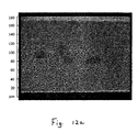
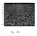
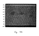
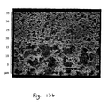
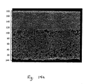
- 238000001000 micrograph Methods 0.000 description 4
- 238000003303 reheating Methods 0.000 description 4
- 241000894006 Bacteria Species 0.000 description 3
- 230000015572 biosynthetic process Effects 0.000 description 3
- 238000007906 compression Methods 0.000 description 3
- 230000006835 compression Effects 0.000 description 3
- 238000013461 design Methods 0.000 description 3
- 238000001035 drying Methods 0.000 description 3
- 230000007935 neutral effect Effects 0.000 description 3
- 229910052757 nitrogen Inorganic materials 0.000 description 3
- 239000012299 nitrogen atmosphere Substances 0.000 description 3
- 238000001878 scanning electron micrograph Methods 0.000 description 3
- 238000000926 separation method Methods 0.000 description 3
- OSWFIVFLDKOXQC-UHFFFAOYSA-N 4-(3-methoxyphenyl)aniline Chemical compound COC1=CC=CC(C=2C=CC(N)=CC=2)=C1 OSWFIVFLDKOXQC-UHFFFAOYSA-N 0.000 description 2
- 101100493705 Caenorhabditis elegans bath-36 gene Proteins 0.000 description 2
- 239000004743 Polypropylene Substances 0.000 description 2
- 229920006100 Vydyne® Polymers 0.000 description 2
- 239000000654 additive Substances 0.000 description 2
- 210000001124 body fluid Anatomy 0.000 description 2
- 239000010839 body fluid Substances 0.000 description 2
- 238000010924 continuous production Methods 0.000 description 2
- 230000001419 dependent effect Effects 0.000 description 2
- 238000011161 development Methods 0.000 description 2
- 239000012502 diagnostic product Substances 0.000 description 2
- 235000019253 formic acid Nutrition 0.000 description 2
- 238000005374 membrane filtration Methods 0.000 description 2
- 238000001471 micro-filtration Methods 0.000 description 2
- 229920002959 polymer blend Polymers 0.000 description 2
- 229920001155 polypropylene Polymers 0.000 description 2
- 238000011045 prefiltration Methods 0.000 description 2
- 238000002203 pretreatment Methods 0.000 description 2
- 125000002924 primary amino group Chemical group [H]N([H])* 0.000 description 2
- 230000009467 reduction Effects 0.000 description 2
- 238000012958 reprocessing Methods 0.000 description 2
- 239000002356 single layer Substances 0.000 description 2
- 238000007669 thermal treatment Methods 0.000 description 2
- 239000012498 ultrapure water Substances 0.000 description 2
- 239000011800 void material Substances 0.000 description 2
- 238000005406 washing Methods 0.000 description 2
- 239000002699 waste material Substances 0.000 description 2
- 238000012935 Averaging Methods 0.000 description 1
- OFOBLEOULBTSOW-UHFFFAOYSA-N Malonic acid Chemical compound OC(=O)CC(O)=O OFOBLEOULBTSOW-UHFFFAOYSA-N 0.000 description 1
- 239000004695 Polyether sulfone Substances 0.000 description 1
- 240000004808 Saccharomyces cerevisiae Species 0.000 description 1
- 244000269722 Thea sinensis Species 0.000 description 1
- 150000001413 amino acids Chemical class 0.000 description 1
- 239000003963 antioxidant agent Substances 0.000 description 1
- 238000005452 bending Methods 0.000 description 1
- 230000033228 biological regulation Effects 0.000 description 1
- 238000009835 boiling Methods 0.000 description 1
- 239000003795 chemical substances by application Substances 0.000 description 1
- 239000002131 composite material Substances 0.000 description 1
- 239000000470 constituent Substances 0.000 description 1
- 239000000356 contaminant Substances 0.000 description 1
- 238000007796 conventional method Methods 0.000 description 1
- 230000003247 decreasing effect Effects 0.000 description 1
- 230000007547 defect Effects 0.000 description 1
- 238000007872 degassing Methods 0.000 description 1
- 150000004985 diamines Chemical class 0.000 description 1
- 238000011143 downstream manufacturing Methods 0.000 description 1
- 230000009977 dual effect Effects 0.000 description 1
- 210000003743 erythrocyte Anatomy 0.000 description 1
- 230000001747 exhibiting effect Effects 0.000 description 1
- 230000003631 expected effect Effects 0.000 description 1
- 238000002474 experimental method Methods 0.000 description 1
- 238000011010 flushing procedure Methods 0.000 description 1
- 239000006260 foam Substances 0.000 description 1
- 239000007789 gas Substances 0.000 description 1
- 238000010348 incorporation Methods 0.000 description 1
- 238000002347 injection Methods 0.000 description 1
- 239000007924 injection Substances 0.000 description 1
- 238000009434 installation Methods 0.000 description 1
- 210000003127 knee Anatomy 0.000 description 1
- 150000003951 lactams Chemical class 0.000 description 1
- 238000003475 lamination Methods 0.000 description 1
- 230000000873 masking effect Effects 0.000 description 1
- 239000011159 matrix material Substances 0.000 description 1
- 238000002844 melting Methods 0.000 description 1
- 230000008018 melting Effects 0.000 description 1
- 238000012986 modification Methods 0.000 description 1
- 230000004048 modification Effects 0.000 description 1
- 230000000704 physical effect Effects 0.000 description 1
- 229920002492 poly(sulfone) Polymers 0.000 description 1
- 229920006393 polyether sulfone Polymers 0.000 description 1
- 229920006254 polymer film Polymers 0.000 description 1
- 239000002861 polymer material Substances 0.000 description 1
- 229920005597 polymer membrane Polymers 0.000 description 1
- 238000004382 potting Methods 0.000 description 1
- 238000004886 process control Methods 0.000 description 1
- 230000002250 progressing effect Effects 0.000 description 1
- 230000002787 reinforcement Effects 0.000 description 1
- 238000012827 research and development Methods 0.000 description 1
- 229920005989 resin Polymers 0.000 description 1
- 239000011347 resin Substances 0.000 description 1
- 230000004044 response Effects 0.000 description 1
- 238000005070 sampling Methods 0.000 description 1
- 238000011012 sanitization Methods 0.000 description 1
- 238000007764 slot die coating Methods 0.000 description 1
- 241000894007 species Species 0.000 description 1
- 238000005507 spraying Methods 0.000 description 1
- 230000000087 stabilizing effect Effects 0.000 description 1
- 230000003068 static effect Effects 0.000 description 1
- 238000011146 sterile filtration Methods 0.000 description 1
- 239000000126 substance Substances 0.000 description 1
- 239000004094 surface-active agent Substances 0.000 description 1
- 229920001897 terpolymer Polymers 0.000 description 1
- 230000001131 transforming effect Effects 0.000 description 1
- 230000007723 transport mechanism Effects 0.000 description 1
- 238000009966 trimming Methods 0.000 description 1
- 238000010977 unit operation Methods 0.000 description 1
- 238000011144 upstream manufacturing Methods 0.000 description 1
- 238000010200 validation analysis Methods 0.000 description 1
Images

Classifications
-
- B—PERFORMING OPERATIONS; TRANSPORTING
- B01—PHYSICAL OR CHEMICAL PROCESSES OR APPARATUS IN GENERAL
- B01D—SEPARATION
- B01D69/00—Semi-permeable membranes for separation processes or apparatus characterised by their form, structure or properties; Manufacturing processes specially adapted therefor
- B01D69/10—Supported membranes; Membrane supports
- B01D69/108—Inorganic support material
-
- B—PERFORMING OPERATIONS; TRANSPORTING
- B01—PHYSICAL OR CHEMICAL PROCESSES OR APPARATUS IN GENERAL
- B01D—SEPARATION
- B01D71/00—Semi-permeable membranes for separation processes or apparatus characterised by the material; Manufacturing processes specially adapted therefor
- B01D71/06—Organic material
- B01D71/56—Polyamides, e.g. polyester-amides
-
- B—PERFORMING OPERATIONS; TRANSPORTING
- B01—PHYSICAL OR CHEMICAL PROCESSES OR APPARATUS IN GENERAL
- B01D—SEPARATION
- B01D67/00—Processes specially adapted for manufacturing semi-permeable membranes for separation processes or apparatus
- B01D67/0002—Organic membrane manufacture
- B01D67/0009—Organic membrane manufacture by phase separation, sol-gel transition, evaporation or solvent quenching
- B01D67/0011—Casting solutions therefor
-
- B—PERFORMING OPERATIONS; TRANSPORTING
- B01—PHYSICAL OR CHEMICAL PROCESSES OR APPARATUS IN GENERAL
- B01D—SEPARATION
- B01D69/00—Semi-permeable membranes for separation processes or apparatus characterised by their form, structure or properties; Manufacturing processes specially adapted therefor
- B01D69/10—Supported membranes; Membrane supports
-
- B—PERFORMING OPERATIONS; TRANSPORTING
- B01—PHYSICAL OR CHEMICAL PROCESSES OR APPARATUS IN GENERAL
- B01D—SEPARATION
- B01D69/00—Semi-permeable membranes for separation processes or apparatus characterised by their form, structure or properties; Manufacturing processes specially adapted therefor
- B01D69/12—Composite membranes; Ultra-thin membranes
- B01D69/1213—Laminated layers
-
- B—PERFORMING OPERATIONS; TRANSPORTING
- B01—PHYSICAL OR CHEMICAL PROCESSES OR APPARATUS IN GENERAL
- B01D—SEPARATION
- B01D2323/00—Details relating to membrane preparation
- B01D2323/12—Specific ratios of components used
Definitions
- the present disclosure relates to systems and methods for the manufacture of continuous, three-zone reinforced, geometrically symmetrical, microporous membranes having three distinct pore zones, each zone being formed from at least one of a plurality of different pore size producing dopes, more particularly to systems and methods for the continuous manufacture of continuous, reinforced, three-zone microporous membrane including a scrim having two sides at least substantially encapsulated within any one of a plurality pore size producing first dopes produced from a single mother dope batch and at least one additional dope presently preferably produced from the same single mother dope batch coated onto each side of the substantially encapsulated scrim prior to the first dope being quenched and, most particularly, to systems and methods for the manufacture of a geometrically symmetric, continuous, reinforced membrane having three distinct pore zones including a scrim at least substantially and preferably, completely encapsulated by a relatively large pore size middle zone produced from any one of a plurality of different pore size dopes, which may be continuously produced from a single mother do
- Microporous phase inversion membranes are well known in the art. Microporous phase inversion membranes are porous solids which contain microporous interconnecting passages that extend from one surface to the other. These passages provide tortuous tunnels or paths through which the liquid which is being filtered must pass. The particles contained in the liquid passing through a microporous phase inversion membrane become trapped on or in the membrane structure effecting filtration. A slight pressure, generally in the range of about one half (0.5) to about fifty (50) psig (pounds per square inch gauge) is used to force fluid through the microporous phase inversion membrane.
- microporous phase inversion membrane prevents particles of a certain size or larger from passing through it, while at the same time permitting liquid and some particles smaller than that certain size to pass through.
- Microporous phase inversion membranes have the ability to retain particles in the size range of from about 0.01 or smaller to about 10.0 microns or larger.
- microporous membranes Many important micron and submicron size particles can be separated using microporous membranes. For example, red blood cells are about eight (8) microns in diameter, platelets are about two (2) microns in diameter and bacteria and yeast are about 0.5 microns or smaller in diameter. It is possible to remove bacteria from water by passing the water through a microporous membrane having a pore size smaller than the bacteria. Similarly, a microporous membrane can remove invisible suspended particles from water used in the manufacture of integrated circuits in the electronics industry.
- Microporous membranes are characterized by bubble point tests, which involve measuring the pressure to force either the first air bubble out of a fully wetted phase inversion membrane (the initial Bubble Point, or "IBP"), and the higher pressure which forces air out of the majority of pores all over the phase inversion membrane (foam-all-over-point or "FAOP").
- IBP initial Bubble Point
- FAOP beam-all-over-point
- the procedures for conducting initial bubble point and FAOP tests are discussed in U.S. Patent No. 4,645,602 issued February 24, 1987, the disclosure of which is herein incorporated by reference.
- the procedure for the initial bubble point test and the more common Mean Flow Pore tests are explained in detail, for example, in ASTM F316-70 and ANS/ASTM F316-70 (Reapproved 1976) which are incorporated herein by reference.
- the bubble point values for microporous phase inversion membranes are generally in the range of about two (2) to about one hundred (100) psig, depending on the pore size and the wetting
- microporous phase inversion membrane As was pointed out in the '295 application, during production runs of microporous phase inversion membrane, it is important to produce microporous phase inversion membrane having the desired pore size and/or pore size distribution.
- the dope formulation (solvent, nonsolvent, polymer ratio) was key to controlling pore size in the microporous phase inversion membrane.
- the batch formulation method as a predictive control of pore size in microporous phase inversion membrane, microporous phase inversion membrane having a specific pore size was produced from a specifically formulated dope batch.
- thermal manipulation to change the pore size in a membrane produced from a dope has long been recognized and has been used in reprocessing out of specification dope, as discussed therein.
- this recognized property of the dope was dependent on raising the temperature of the dope to a temperature higher than that to which the dope had previously been processed.
- one prior patent mentioned in the '295 application discussed controlling the process temperature as one factor in enabling continuous production of material with fixed or variable pore size from a single batch of nylon 46 solution, that prior patent failed to provide any specific temperatures other than a wide temperature range.
- the patent combined process temperature manipulation with the composition of the dope and the composition of the bath to effectuate the pore size change but only in one direction, from smaller to larger. There was no apparent effort to control the temperature of the solution at a specific temperature or any effort to try to lower the temperature of the solution to produce a smaller pore size.
- the methods disclosed in the patent must restrict the casting solution viscosity to a very narrow practical range, to ensure wetting of the substrate, minimization of entrapped air, and "smooth, even coating of the mixture," to ensure the integrity of the finished membrane product.
- a practical limit to the solution viscosity therefore a single stage thermal treatment and hot casting would potentially lower the viscosity to an impractical point, thus limiting the useful range of resultant pore sizes.
- the single stage thermal treatment and hot casting would be harmful to the resulting product, in the volatile non-solvent components of the Marinaccio style dope (Methanol and Methyl Formate) will de-gas in an uncontrolled manner upon casting at a temperature above thirty-four degrees (34°) C (boiling point of Methyl Formate), and form bubbles, voids and other imperfections in the surface and matrix of the membrane. These voids are not desirable in commercial microporous membrane.
- the prior art can be described as a non-real time predictive batch-type process that uses formulation to initially control pore size and bulk reheating as a predictive thermal manipulation to produce a predictive pore size to correct an improperly formulated batch, or improperly controlled initial mix cycle, sheer speed control to introduce the nonsolvent in the preparation of the dope as a batch of liquid to be processed into a membrane and bath solvent control in order to vary the pore size.
- the dope had a viscosity related to the process temperature. There was no apparent attempt to independently control the viscosity of the dope prior to moving the dope to a membrane production apparatus.
- a relatively thin, geometrically symmetrical, continuous, monolithic, reinforced, polymeric microfiltration membrane having at least three independent and distinct pore size performance zones (one reinforced performance zone, presently preferably, central to the membrane structure, and two outer non-reinforced performance zones including at least one outer qualifying performance zone on one side of the central reinforced zone and a second outer non-qualifying prefilter performance zone on the other side of the central performance zone or, two outer qualifying performance zones, one on each side of the central zone) progressing through the thickness of the membrane, each zone being continuously joined throughout the membrane structure utilizing at least one mother dope batch to provide any one of a plurality of different pore size dope to any one of the three zones.
- Such systems and methods should produce a three-zone membrane structure by a highly robust, single unit operation, with on-line pore size and layer thickness attribute control. Such systems and methods should produce a three-zone membrane that meets the industry's long recognized need for superior performance and greater flexibility of triple layer composite structures having any one of a plurality of pore sizes in any one of the three zones. Such systems and methods for producing a three-zone membrane should provide for the relatively inexpensive manufacture in a continuous process with the capability of changing the pore size in any of the zones including changing dope batches. Such systems and methods of manufacturing a three-zone membrane should eliminate the complex production of traditional laminated single layer structure membrane and increase the range of pore sizes and manageable handling thickness that are provided by the non-reinforced zones.
- Such systems and methods for manufacturing a three-zone membrane should have a geometrically symmetrical structure having improved utility, flexibility, and processability into finished industrial forms (pleated cartridges, etc.) while assuring structural integrity in any one of plurality of different pore sizes in each of the three zones.
- Such systems and methods of manufacturing a three-zone membrane should provide a membrane having a minimum functional thickness and maximum throughput at minimal pressure drops, high integrity and be economically produced such that there is any one of plurality of different pore sizes in each of the three zones.
- Such systems and methods for manufacturing a three-zone microporous membrane should include the formulation of at least one mother dope batch at a temperature equal to or below the target temperature for producing the smallest desired pore size of the possible plurality of pore sizes for each zone to be produced from the at least one mother dope batch.
- Such systems and methods for manufacturing a three-zone microporous membrane should provide for the elevation of selected portions of the at least one mother dope batch to any one of a plurality of target temperatures such that microporous membrane having any one of a plurality of corresponding pore sizes can be simultaneously produced from at least one mother dope batch.
- Such systems and methods for the manufacture of a three-zone microporous membrane should provide for the temperature control of at least a portion of the at least one mother dope batch to about ⁇ 0.2°C of a target temperature prior to that portion of the dope prepared at the target temperature and after cooling being transferred to at least one dope application apparatus of a reinforced, three-zone microporous membrane manufacturing system at a processing site.
- Such systems and methods for the manufacture of the three-zone microporous membrane should provide for the accurate control of the temperature seen by substantially all of that portion of the dope to about ⁇ 0.15°C prior to that portion of the dope being transferred to at least one dope application apparatus of the reinforced, three-zone microporous membrane manufacturing system.
- Such systems and methods for manufacturing three-zone microporous membranes should eliminate the necessity for preparing at least one dope batch according to individual unique formulations for each pore size, thus resulting in significant cost savings and flexibility in the usage of dope batches.
- Such systems and methods for manufacturing reinforced, three-zone microporous membranes should also provide the ability to selectively change the pore size of at least one zone of the three-zone microporous membrane being produced from the at least one mother batch after a certain amount of at least one zone of the reinforced, three-zone microporous membrane has been produced at one specific pore size and begin producing reinforced, three-zone microporous membrane having another pore size in that same zone utilizing the same at least one mother dope batch.
- An object of the present disclosure is to provide systems and methods for manufacturing three-zone, reinforced, continuous, non-laminated, geometrically symmetrical microporous membranes possessing structural integrity.
- Another object of the present disclosure is to provide systems, and methods for manufacturing reinforced, three-zone continuous, non-laminated symmetrical microporous membranes exhibiting low pressure drop and high flow rate across the membrane.
- a further object of the present disclosure is to provide systems, and methods for manufacturing reinforced, three-zone continuous, non-laminated, geometrically symmetrical microporous membranes which are particularly suitable for the filtration of biological or parenteral fluids.
- Yet a further object of the present disclosure is to provide systems and methods for manufacturing reinforced, three-zone continuous, non-laminated, geometrically symmetrical microporous membranes which are particularly suitable for the filtration of high purity water for the electronics industry.
- Yet another object of the present disclosure is to provide systems and methods for manufacturing such a three-zone, continuous, reinforced, non-laminated, geometrically symmetrical microporous membrane.
- the present disclosure provides a system for manufacturing a three-zone microporous membrane from a ternary phase inversion polymer mother dope, the system comprising: at least one vessel for containing the dope; a dope processing site; at least one pressure means, operatively connected to the at least one vessel, and the dope processing site, the at least one pressure means being adapted to move the dope from the at least one vessel to the dope processing site; a dope transportation system, operatively connected to the at least one vessel and the dope processing site, the dope transportation system being adapted to transfer the dope from the at least one vessel to the dope processing site; at least one thermal manipulation means, operatively connected to the at least one vessel and the dope processing site, the at least one thermal manipulation means being adapted to transform the dope to produce a plurality of microporous membranes having desired pore sizes; and at least three dope application means, operative at the dope processing site and operatively connected to the at least one thermal manipulation means
- the system of the disclosure may further comprise at least a second thermal manipulation means, operatively connected to the at least one vessel, the dope transportation system and at least one of the three dope application means, the second thermal manipulation means being adapted to transform the dope into any one of a plurality of different possible pore size producing dopes for application at the dope processing site.
- This system may optionally comprise at least a third thermal manipulation means, operatively connected to at least one vessel, the dope transporting system and at least another one of the three dope application means, the third thermal manipulation means being adapted to transform the dope into any one of a plurality of different possible pore size producing dopes for application at the dope processing site.
- the system of the disclosure may further comprise at least a second and a third thermal manipulation means, operatively connected to the at least one vessel and at least two of the three dope application means respectively, the thermal manipulation means being adapted to transform the dope pumped from the at least one vessel to the second and third thermal manipulation means into any one of a plurality of different possible pore size producing dopes for application at the dope processing site.
- the system of the disclosure may further comprise at least a second vessel operatively connected to the dope transporting means, for containing a ternary phase inversion polymer dope.
- This system may optionally further comprise at least a third vessel, operatively connected to the dope transporting system, for containing a ternary phase inversion polymer dope.
- the system of the disclosure may further comprise bypass means operatively connected to the at least one thermal manipulation means, the bypass means being adapted to divert the dope being transported from the at least one vessel to the dope processing site such that the dope is not processed by the at least one thermal manipulation means prior to delivery to the dope processing site.
- the system comprising at least a second thermal manipulation means may further comprise a bypass means, operatively connected to at least the second thermal manipulation means, the bypass means being adapted to divert the dope from at least one vessel to the dope processing site such that the dope is not processed by the at least second thermal manipulation means prior to delivery to the dope processing site.
- the system comprising at least a second and a third thermal manipulation means may further comprise a bypass means operatively connected to at least the third thermal manipulation means, the bypass means being adapted to divert the dope from the at least one vessel to the dope processing site such that the dope is not processed by the at least third thermal manipulation means prior to being delivered to the processing site.
- the thermal manipulation means used in the system of the present disclosure may further comprise heating means, operatively positioned in the at least one thermal manipulation means, the heating means being adapted to elevate the temperature of at least a portion of the dope to a temperature within about ⁇ 0.2°C of a predetermined temperature, the predetermined temperature being selected from a calibrated characterization curve which describes the relationship between the dope being processed and the resulting pore size in at least one zone of the three-zone microporous membrane.
- the thermal manipulation means further comprises cooling means, operatively connected to the at least one thermal manipulation means, the cooling means being adapted to cool the dope after processing by the thermal manipulation means to a temperature such that the dope has a viscosity sufficient for processing by any one of the three dope application means to produce a microporous phase inversion membrane.
- the heating means used with this thermal manipulation means may further comprise first heating means, operatively connected to the pump, the first heating means being adapted to elevate the temperature of at least a portion of the dope to a temperature within about 2°C below the predetermined temperature; and second heating means, operatively connected to the first heating means, the second heating means being adapted to elevate further the temperature of at least a portion of the dope to a temperature no higher than within about ⁇ 0.2°C of the predetermined temperature.
- the second heating means further elevates the temperature of the dope to a temperature no higher than within about ⁇ 0.15°C of the predetermined temperature.
- the system of the present disclosure may further comprise thickness controlling means, operatively positioned between the vessel containing the ternary phase inversion polymer and the dope processing site, the thickness controlling means being adapted to control the thickness of the dope during application by the application means.
- the system of the present disclosure may further comprise weight controlling means, operatively positioned between the vessel containing the ternary phase inversion polymer and the dope processing site, the weight controlling means being adapted to control the coating weight of the dope during application by the application means.
- the dope processing site of the system of the present disclosure is operatively connected to the at least one vessel containing the dope.
- the present disclosure also provides a method for manufacturing three-zone microporous membrane from a ternary phase inversion polymer dope, the method comprising the steps of formulating a ternary phase inversion polymer mother dope in at least one vessel to effect dissolution and equilibrium mixing of the polymer, solvent and nonsolvent; maintaining the mother dope in the at least one vessel at a temperature sufficient to stabilize and maintain the dope formulated after cooling from the formulation temperature; transporting the formulated dope to a dope processing site having at least three dope application means; thermally manipulating the mother dope transported from the at least one vessel using at least one thermal manipulation means to produce a microporous membrane of one of a plurality of different possible pore sizes; and applying a predetermined one of the thermally manipulated dope to a scrim at the dope processing site to produce a reinforced, three-zone microporous membrane.
- the method of the present disclosure may further comprise the steps of thermally manipulating the mother dope transported from the at least one vessel using a second thermal manipulation means into a predetermined one of a plurality of different possible pore size producing dopes; and applying the predetermined one of the plurality of different possible pore size producing dopes received from each of the two thermal manipulation means to a scrim that has had a thermally manipulated dope applied thereto from one of two thermal manipulation means to produce a reinforced, three-zone microporous membrane.
- This method may further comprise the steps of thermally manipulating the mother dope transported from the at least one vessel using a third thermal manipulation means into a predetermined one of a plurality of different possible pore size producing dopes; and applying the predetermined one of the plurality of different possible pore size producing dopes received from each of the three thermal manipulation means to a scrim at the dope processing site to a produce reinforced, three-zone microporous membrane.
- This method may further comprise the steps of providing at least a second vessel for containing a ternary phase inversion polymer mother dope, the dope having been exposed to a mixing temperature sufficient to effect dissolution and equilibrium mixing of the polymer, solvent and nonsolvent, the vessel and the dope contained therein being maintained at a temperature sufficient to stabilize and maintain the mixture after cooling from the mixing temperature.
- the temperature of the mother dope is preferably incrementally elevated to a temperature no higher than within about ⁇ 0.15°C of the predetermined temperature.
- the method in which a third thermal manipulation means is used may further comprise the steps of providing at least a third vessel for containing a ternary phase inversion polymer mother dope, the dope having been exposed to a mixing temperature sufficient to effect dissolution and equilibrium mixing of the polymer, solvent and nonsolvent the vessel and the dope contained therein being maintained at a temperature sufficient to stabilize and maintain the mixture after cooling from the mixing temperature.
- the mother dope may further comprise a phase inversion membrane polymer, a solvent and nonsolvent in solution.
- the phase inversion membrane polymer is preferably selected from the group consisting of copolymers of hexamethylene diamine and adipic acid (nylon 66), copolymers of hexmethylene diamine and sebacic acid (nylon 610), homopolymers of polycaprolactam (nylon 6) and copolymers of tetramethylenediamine and adipic acid (nylon 46). More preferably, the phase inversion membrane polymer consists of copolymers of hexamethylene diamine and adipic acid (nylon 66).
- Suitable phase inversion membrane polymers include polyamide resins have a ratio of methylene (CH 2 ) to amide (NHCO) groups within the range of about 4:1 to about 8:1, preferably within the range of about 5:1 to about 7:1.
- the phase inversion membrane polymer has a molecular weight, within the range from about 15,000 to about 42,000 (number average molecular weight).
- the phase inversion membrane polymer is polyhexamethylene adipamide (nylon 66) having a molecular weight above about 30,000 (number average molecular weight).
- Another aspect of the present disclosure includes a system for manufacturing three-zone microporous membrane, the system comprising: at least one vessel for containing a ternary phase inversion polymer mother dope; a dope processing site, operatively connected to the at least one vessel containing the ternary phase inversion polymer mother dope; a dope transportation system, operatively connected to the at least one vessel and to the dope processing site, for transporting the dope from the vessel to the dope processing site; pump means, operatively connected to the at least one vessel, for moving the dope from the at least one vessel to the dope processing site; at least three thermal manipulation means, operatively connected to the at least one vessel, the dope transportation system and the dope processing site, for transforming the dope into any one of a plurality of different possible pore size producing dopes; and at least three dope application means, each operatively connected to a respective one of the three thermal manipulation means for application of the dope delivered to the dope processing site.
- Still another aspect of the present disclosure includes a three-zone microporous membrane prepared by a method for manufacturing a three-zone microporous membrane, the method comprising the steps of: providing at least one vessel for containing a ternary phase inversion polymer mother dope; formulating a ternary phase inversion polymer mother dope in the at least one vessel to effect dissolution and equilibrium mixing of the polymer, solvent and nonsolvent; maintaining the mother dope in the vessel at a temperature sufficient to stabilize and maintain the dope formulated after cooling from the formulation temperature; providing a dope processing site having at least three dope application means; operatively connecting the at least one vessel to the dope processing site such that the mother dope is transported from the at least one vessel to the dope processing site; operatively positioning at least one thermal manipulation means between the at least one vessel and the dope processing site; thermally manipulating the mother dope transported from the at least one vessel in the at least one thermal manipulation means into any one of a plurality of different possible pore size producing dopes; and applying
- Microporous phase inversion membranes produced using the systems and methods of the present disclosure are preferably produced from nylon.
- nylon is intended to embrace film forming polyamide resins including copolymers and terpolymers which include the recurring amino grouping and blends of different polyamide resins.
- the nylon is a hydrolytically stable nylon possessing at least about 0.9 moles of amino end groups per mole of nylon as described in U.S. Patent No. 5,458,782, the disclosure of which is incorporated herein by reference.
- nylon or polyamide resins While in general the various nylon or polyamide resins are all copolymers of a diamine and a dicarboxylic acid, or homopolymers of a lactam and an amino acid, they vary widely in crystallinity or solid structure, melting point, and other physical properties.
- Preferred nylons for use with the methods and systems of this application are copolymers of hexamethylene diamine and adipic acid (nylon 66), copolymers of hexmethylene diamine and sebacic acid (nylon 610), homopolymers of polycaprolactam (nylon 6) and copolymers of tetramethylenediamine and adipic acid (nylon 46).
- nylon polymers have a ratio of methylene (CH 2 ) to amide (NHCO) groups within the range of about 4:1 to about 8:1, most preferably about 5:1 to about 7:1.
- the nylon polymers are available in a wide variety of grades, which vary appreciably with respect to molecular weight, within the range from about 15,000 to about 42,000 (number average molecular weight) and in other characteristics.
- the highly preferred species of the units composing the polymer chain is polyhexamethylene adipamide, i.e. nylon 66, having molecular weights above about 30,000.
- Polymers free of additives are generally preferred, but the addition of antioxidants, surface active agents, charge modifying agents or similar additives may have benefit under some conditions.
- one conventional method for processing dope containing the above mentioned polamide resins into microporous phase inversion membrane is carried out by formulating a specific dope according to a known formula to produce a certain pore size when the dope is cast into microporous phase inversion membrane.
- the dope comprises a polymer, a solvent and non-solvent in a specific predetermined amount mixed and stored in a sealed storage vessel.
- the dope batch is formulated in accordance with a predetermined formula under controlled conditions including a maximum mixing temperature, the dope is then pumped to a casting line and at that point cast into a microporous phase inversion membrane.
- thermal heat treatment of dope only works in one direction and that is to enlarge the pore size of the resultant membrane, not to decrease pore size of the resultant membrane.
- a temperature memory associated with the polymer mixture and that the pore size in any membrane produced therefrom is associated with the highest temperature to which the polymer mixture has been exposed prior to being processed into membrane.
- This "temperature memory” is permanent as far as a specific temperature is concerned.
- a pump preferably a metering pump
- thermal manipulation mechanism or means including a first heating zone for elevating the temperature of that relatively small portion of the dope.
- the smaller portion of the dope was pumped to a second heating zone of the thermal manipulation mechanism or means, for incrementally elevating the temperature of the dope to a target temperature.
- the thermally manipulated dope was then transported to a cooling zone where the dope was cooled to a temperature and a viscosity sufficient for processing at the dope processing site into at least one zone of a reinforced, three-zone microporous phase inversion membrane, it being understood that the viscosity of the cooled dope, already thermally manipulated to produce a specific pore size, may be independently manipulated by controlling the cooling temperature in order to optimize the viscosity of the dope at the reinforced, three-zone membrane manufacturing apparatus.
- The, presently preferred, mother dope for producing the widest range of possible pore sizes from the smallest to the largest pore size was formulated to provide a dope with the maximum non-solvent to solvent ratio attainable at the specific formulation weight percentage of the polymer. It was understood that the ratio of non-solvent to solvent could be less than the maximum and still produce a range of pore sizes but not necessarily provide the maximum flexibility to produce phase inversion membrane having the widest possible range of pore sizes.
- the temperature of the small portion of the dope in the first heating zone was, presently preferably, elevated to within about two degrees (2°) C below a predetermined target temperature.
- the predetermined target temperature can be any of a plurality of possible target temperatures at which the dope has been determined to yield a particular microporous phase inversion membrane pore size when processed into microporous phase inversion membrane.
- the temperature of the dope within that first heating zone was then elevated to within about ⁇ 0.5°C of about 2°C below the target temperature by using temperature control apparatus, as will be explained below.
- the highest temperature that the small portion of the dope was exposed to during the movement of the dope through the first heating zone of the first thermal manipulation mechanism or means was, presently preferably. about 1.5°C below each specific predetermined target temperature.
- the relatively small amount of dope was further processed through the second heating zone wherein the temperature of the dope was further elevated and controlled to within about ⁇ 0.15°C of the one specific target temperature.
- the dope Upon achieving a dope temperature of about ⁇ 0.15°C of one specific target temparature, the dope exited the second heating zone of the thermal manipulation mechanism or means and was, presently preferably, cooled in a cooling zone of the thermal manipulation mechanism or means to a temperature, presently preferably, about twenty-one degrees (21°) C, or other temperance that provides the dope with an appropriate viscosity for appropriate application and, after sampling and testing, was further pumped to a phase inversion membrane production facility or dope processing site for processing into microporous phase inversion membrane having the predetermined pore size corresponding to the target tempetature.
- a phase inversion membrane production facility or dope processing site for processing into microporous phase inversion membrane having the predetermined pore size corresponding to the target tempetature.
- the dope be thermally manipulated to a precise predetermined temperature that produces a specific pore size in microporous phase inversion membrane and was then cooled back down to a temperature which independently controls the viscosity of the dope during the casting process, all within about ten (10) minutes, considerably ten time than any known process has previously controlled the temperature elevation phase alone during, such as, reprocessing an out of specification dope.
- a valve located in the dope process line provides for the withdrawal of dope samples from the line for testing to ensure that the dope will produce microporous phase inversion membrane having the specific pore size desired. Additionally, the valve also provides for the of the dope after the dope exits the cooling zone and returns the dope to the dope process line at a point prior to the first heating zone or other location, as appropriate.
- thermally manipulating dope includes the surprising ability to produce, from a single mother dope, phase inversion membrane having a range of pore sizes greater than previously produced, from about 0.05 microns or smaller to about 50 microns or larger, an order of magnitude of about three (3).
- microporous membrane production can be accomplished in any sequence as long as the desired pore size is not one that requires an initial formulation mixing temperature less than the formulation mixing temperature of the mother dope.
- the methods and systems of the above described systems and methods for thermally manipulating the pore size in dopes use real time essentially instantaneous, about ten (10) minutes or less and no more than about five (5) to about (20) twenty minutes for the total thermal manipulation cycle as opposed to three to five hours for the prior art thermal manipulation to independently control dope viscosity and resulting phase inversion membrane pore size in the production of chase inversion membrane.
- the systems and the methods of the present disclosure are designed to exploit, to the maximum advantage, the permanent thermal memory of the phase inversion membrane casting dopes.
- thermal manipulations occur between the inlet to the first heat exchanger and the outlet of the final cooling mechanism or means or heat exchanger.
- volume of about five gallons of the dope was being processed through the thermal manipulation mechanism or means (heat exchangers) at any one time between those two points at a speed of about one-half (0.5) to about three-quarters (0.75) of a gallon per minute (GPM).
- GPM gallon per minute
- the about five (5) gallons of dope an thermally manipulated in about ten (10) minutes or less to a point where the dope was ready for coating at a coating apparatus.
- the temperature manipulation of the systems and methods of the present disclosure is accomplished by precisely controlling the temperature of the dope as the dope is pumped through each of the heat exchangers to a very precise point over a large surface area or heat transfer area within the first and third heat exchangers so that essentially each element of the fluid sees essentially the same temperature manipulation.
- the static mixer/heat exchanger continuously pushes fluid, such as dope, from the center of the heat exchanger to the wall than back to the center again, substantially eliminating thermal gradients and boosting, the inside film coefficient to essentially convert laminar flow to turbulent flow to enhance mixing.
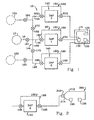
- Figure 1 is a shematic representation of one representative system 10 for implementing the methods of the present disclosure.
- the system 10 includes a plurality of processing stations and processing mechanisms beginning with the mother batch of dope contained in the storage vessel 12, presently preferably, under about forty-five (45) psi pressure, and ending with the dope being processed at a dope processing site 14 into reinforced, three-zone microporous phase inversion membrane 101 (see Figure 7).
- the systems and methods of the present disclosure begin with the preparation of a mother dope, as described in the 09/022,295 application.
- the dope is then transported to at least one thermal manipulation mechanism or means, or Dial-A-PorTM unit and preferably at least two Dial-A-PorTM units where the dope is incrementally thermally manipulated to provide a dope that.
- the membrane production process begins by formulating a mother batch of dope by mixing various constituents known in the art in a conventional dope storage vessel 12.
- Dope preparation is similar to the dope preparation discussed in U.S. Patent No. 4,645,602, issued on February 24, 1987, assigned to the assignee of the present application, the disclosure of which is incorporated herein by reference.
- the sealed storage vessel 12 is typically maintained in an inert nitrogen atmosphere from about zero (0) to about fifty (50) psig.
- the vessel is preferably pressurized to approximately forty-five (45) psig with nitrogen.
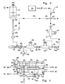
- the storage vessel 12 includes conventional temperature control mechanism or means, such as, for example, a water or liquid jacket surrounding the dope and conventional fluid mixing mechanism or means 16 such as a rotating device for agitating the dope inside the storage vessel 12 (see Figure 3).
- Fluid transport mechanism or means 18, such as, for example, conventional pipe or hose, are operatively connected to the bottom 20 of the vessel 12 for sequentially transporting a small portion of the dope, after stabilizing the formulation, initially at a temperature of about twenty-one degrees (21°) C to about twenty-eight (28°) C (or any suitable initial processing temperature for the dope) contained in the vessel to a coating apparatus.
- a, presently preferably, 150 micron filter 22 for separating foreign matter, solid contaminants and any suspended particulate solid particles from the dope is operatively positioned in the hose.
- One filter 22 found to be useful in performing this function is, presently preferably, a CTG-KLEAN filter housing manufactured by CUNO as Part No. 1WTSR1 with a 150 micron cartridge installed.
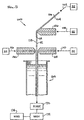
- the scrim 102 is fed by the conventional drive section, downwardly between, presently preferably, a series of dies, including the first die 126 for, presently preferably, completely pressure impregnating the scrim 102 with a first dope 108 and second 128 and third 130 dies for coating a second 110 and a third 116 dope on to the outer surfaces 112, 118 of the dope impregnated scrim 114.
- the first die 126 is a single slot die, operatively connected to a suitable reservoir 60 containing the first dope 108 or, presently preferably metering pump 402 (see Figure 8) for delivering the first dope 108 to the die 126 at the appropriate pressure.
- the first dope may vary depending on the type of film-forming polymer used, but is generally a liquid dope formulated and treated to produce a specific pore size when quenched.
- a conventional controlled pumping mechanism or metering pump 402 (schematically shown) operates to selectively deliver the first dope 108 from the reservoir 60 or from the Dial-A-PorTM unit 25 to the first die 126.
- the first die 126 has an opening configured to provide an even amount of the first dope 108 so as to pressure impregnate the scrim 102 as the scrim 102 passes by the opening of the first die 126.
- the die 126 may be changed for appropriate scrim impregnation. It is important that the first dope 108 transferred to the scrim 102 substantially completely saturate or impregnate the scrim, as was discussed above.
- the scrim travels between the second 126 and third 130 dies.
- the scrim 102 is disposed vertically and travels in the downward direction. In one, presently preferred embodiment of the apparatus, the scrim 102 may initially travel at an angle less than vertical, as illustrated in Figure 2.
- Second 126 and third 130 dies are essentially disposed on opposite sides of the scrim 102 in order to produce the membrane of the present invention.
- Second die 128 is directed to coat the polymer dope 110 desired onto the first surface 112 of the substantially saturated scrim 102 and in like manner, third die 130 is directed to coat the polymer dope 116 desired onto the second surface 118 of the substantially saturated scrim 102.
- Each die 128, 130 is fed from a reservoirs 62, 64 having the dopes 110, 116 or from a metering pump 400, 404, as illustrated in Figure 8.
- the dopes may be a combination of any of the well-known film-forming polymers in an appropriate well-known solvent Controlled pumping mechanisms or metering pumps 400, 404 selectively deliver the dope 110,116 to the dies 128, 130.
- the dies 128, 130 are each disposed on opposite sides of the pressure impregnated scrim 102 and essentially opposed to the other die.
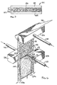
- Each die 128, 130 has a chamber 272 for receiving the dope solution and a narrow slot 274, transversely extending across each side of the front 275 of each die, for first transferring the dope solution onto the impregnated scrim 102 (via die 126) and then to coat the substantially saturated scrim on both sides 112, 118 (via dies 128, 130).
- the dope is forced out of the slots 274 in each die by the pressure supplied by the metering pumps (not shown), in a manner known in the art.
- the pressure provided to the dope varies with each dope and scrim used. Determination of the appropriate pressure for any of the dopes applied to a particular scrim can be determined by those skilled in the art.
- the dies 128, 130 are positioned close enough to the substantially saturated, impregnated scrim 102 so that the dope directly contacts the outer surface of the dope saturated scrim 102 when the dope is forced from the slot 274. As is apparent in Figure 6, the length of the slot 274 determines the final width of the dope coated onto the saturated scrim. By masking or other appropriate means, it is possible to foreclose coating the dope at the edges of scrim 102, leaving a selvage area 276 for trimming, potting or other post-formation operations.
- the initial dope may be different from the other dope(s) and that it is possible to have three different dopes, with a first dope impregnating the scrim 102 and the second and third dopes coated on each side of the first dope impregnated scrim, resulting in a graded density three-zone membrane.
- a metering pump 24 for incrementally transporting a relatively small portion of the dope contained in the vessel 12 from the vessel to the dope processing site 14.
- a type 1 rotating gear pump manufactured by Roper Pumps, model number 005SSIPT4DJMCW, delivering about 0.03 to about 0.5 gallon per minute.
- a first thermal manipulation means or Dial-A-PorTM unit 25 downstream from the pump 24 and operatively connected thereto is a first thermal manipulation means or Dial-A-PorTM unit 25 (See Figure 1) which includes a first mechanism or means or first heating means 26, for elevating or increasing the temperature of the small portion of the dope to within, presently preferably, about two degrees (2.0°) C below a predetermined temperature.
- the first heating means 26 includes a temperature controller 28, (shown schematically in Figure 3).
- the temperature controller 28 is operatively connected to a plate heat exchanger 30, presently preferably, having about a twenty (20) square foot heat transfer area or any area sufficient to accomplish the temperature elevation of the dope to about two degrees (2.0°) C below a predetermined target temperature.
- a plate heat exchanger 30 is available from Tranter, as Model No. MX-20-0412-UP-080/0.060.
- the controller 28 is configured to measure the process fluid (water) in the opposite direction of dope flow (counter current).
- the dope is, presently preferably, transferred to a second mechanism or means or second heating means 32 for further increasing or elevating the temperature of the dope.
- the second means 32 presently preferably, consists of a jacketed pilot mixer/heat exchanger 34 such as, for example, those available from Chemineer as a Kenics HX-1/2 Jacketed pilot mixer/heat exchanger, Part No. 033-00128.
- the temperature of the mixer/heat exchanger 34 is, presently preferably, controlled by a heated circulating water bath programmable controller 36 having a temperature control capability of about ⁇ 0.01°C with a display having an accuracy of only about ⁇ 0.2°C.
- controller 36 is configured to measure the process fluid (water) in the opposite direction of dope flow (counter current).
- the cooling means 40 includes a heat exchanger 41 and a controller 45.
- the cooling means 40 is used to reduce the temperature of the relatively small amount of dope exiting the second heating means 32 at the target temperature to the ambient coating temperature of about twenty one degrees (21°) C, or other temperature which provides an appropriate dope viscosity, while the dope is being processed through a heat exchanger 41 having about a 20 sq. ft. heat transfer area.
- One heat exchanger found to be acceptable to perform the heat exchanger function is a Tranter, Model No.
- the controller 45 is configured to measure the process fluid (water) in the opposite direction of dope flow (counter current).
- the dope is pumped to a valve 42 (in Figure 3) operatively positioned in the dope process loop 46 where samples of the dope exiting the cooling means 40 can be drawn and tests can be run thereon to determine the pore size that the dope will produce in microporous membrane after coating.
- a valve 42 in Figure 3
- Another position 44 for the valve 42 provides for dope recirculation within the dope process line to a position between the storage vessel 12 and the metering pump 24 or other appropriate location.
- a recirculation loop 46 can be actuated, which enables the system to reach a steady state temperature prior to the membrane coating being commenced at the dope processing site 14. Additionally, running in the recirculation loop 46 prevents the production of out-of-specification microporous phase inversion membrane until after receiving the test results from the samples taken of the dope exiting the cooling means 40. Once it is determined that the dope has, in fact, been stabilized at the appropriate predetermined target temperature for producing the appropriate pore size in microporous membrane, then the valve 42 can be moved to position 50 to deliver the dope to the dope processing site 14.
- Additional components of the dope processing system 310 include pressure gauges 60 positioned at various locations as illustrated in Figure 3.
- the pressure gauges positioned on either side of the pump 24 obtain the differential pressure across the pump and the head pressure to the pump. Additional pressure gauges are operatively positioned downstream from each heat exchanger means, 26, 32, and 40 to monitor the pressure drop after the dope has processed through each heat exchanger means for undesirable pressure build up.
- Omega thermistors 62 having a precision of about ⁇ 0.15°C are operatively positioned on the downstream sides of the first 26 and the second 32 heat exchanger means for providing a more accurate temperature reading of the downstream process than the Conair or the Haake units displays are capable of providing.
- the thermistors 62 provide the capability to read the temperature to an accuracy of about ⁇ 0.15°C for increased temperature control whereas the Haake unit is capable of controlling the temperature accuracy to ⁇ 0.01°C.
- One additional feature in the system of the present application includes a pressure relief valve 64 operatively positioned in the loop 46 for protecting the system from damage from excess pressure buildup by taking the pump out of operation should the pressure exceed a predetermined pressure, presently about 250 psi. If the pressure were to exceed a certain pressure, then the dope would be recirculated through the pump via hose 66 (see Figure 4).
- An RTD 70 is operatively positioned in the loop and connected to the Haake recirculation bath 36 for controlling the temperature of the dope in the second heat exchanger means 32.
- Another RTD probe (not shown) is located inside the Haake recirculation bath 36.
- the external RTD probe 70 is the controlling loop unless the probe indicates that the temperature of the dope is outside the maximum setpoint differential, control reverts to the internal RTD probe for controlling the process to the setpoint.
- the Haake is a proportional band controller utilizing Fuzzy Logic PID having the two above described RTDs, one internal and one external to mininnize the temperature differential between the dope and the process fluid.
- the Dial-A-PorTM units 25, 140, 142 are, in their presently preferred embodiment, two stage units which use the high temperature memory of a dope to control pore size, and the cooling cycle to independently control the viscosity of the dope at a coating apparatus, In this manner, the thermal manipulation of the dope alone is sufficient to produce a wide range of commercially useful phase inversion membranes from a single starting dope.
- one, presently preferred, dope processing site 14 or vertical casting line (VCL) apparatus 100 and method for manufacturing a reinforced, three-zone continuous, geometrically symmetrical microporous filtration membrane 101 includes: providing a porous support material 102 having first 104 and second 106 sides, presently preferably, pressure impregnating the support material 102 with a first solution or dope 108 processed to a first temperature, coating a second solution or dope 110 processed to a second temperature over the first side 112 of the pressure impregnated support material 114, coating a third solution or dope 116 processed to the second temperature or to a third temparature over the second side 118 of the pressure impregnated support material 114 such that a continuous microporous membrane having a middle zone 120 disposed between an upper zone 122 and a lower zone 124 (See Figure 7) formed from the first 108, second 110 and third 116 dopes, the support material 102 being, presently preferably, completely embedded within the middle
- the three-zone microporous membrane 101 produced by the system and methods of the present disclosure is generally produced by first pressure impregnating the scrim with a first dope and then coating any one of a plurality of possible different dopes containing a film-forming polymer in a solvent system onto each side of the dope impregnated scrim and immediately quenching the dopes 108, 110, 116 in a bath 138 comprised of a conventional nonsolvent system for the polymer.
- a conventional nonsolvent system for the polymer e.g. pore size
- the selection of the solvent for the polymer is determined by the nature of the polymer material used and can be empirically determined on the basis of solubility parameters, as is well known and conventional in the art.
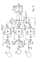
- one, presently preferred, system 10 for manufacturing reinforced, three-zone microporous membrane includes at least one vessel 12, presently preferably, containing a mother dope operatively connected to at least three Dial-A-PorTM dope thermal manipulation units 25, 140, 142 with each of the Dial-A-PorTM units being connected respectively to the first 126, second 128 and third 130 slot dies.
- the system 10 presently preferably, includes a single mother dope vessel 12 from which the dope can be pumped or moved by pressure on the dope in the vessel to a dope transporting mechanism or means piping system 144 having at least three branches 146, 148, 150, each branch being operatively connected to each of the three slot dies, respectively or be pumped, as illustrated in Figure 3.
- a dope transporting mechanism or means piping system 144 having at least three branches 146, 148, 150, each branch being operatively connected to each of the three slot dies, respectively or be pumped, as illustrated in Figure 3.
- Operatively positioned between each of the dies and the mother dope vessel are the three separate Dial-A-PorTM units 25, 140, 142.
- Each Dial-A-PorTM unit is capable of thermally manipulating a portion of the dope from the mother dope batch to a specific predetermined temperature which produces a predetermined pore size and then delivering that thermally manipulated dope to the slot die operatively connected thereto, as described above.
- additional dope containing vessels 152, 154 can also be operatively directly connected to each of the three Dial-A-PorTM units.
- Each of these vessels may contain a specific mother dope as described earlier in the application or it may contain a specific dope formulated to produce a specific pore size or a dope made of a different polymer.
- one dope containing vessel 12 is operatively connected to the dope transporting system and to the first Dial-A-PorTM unit 25
- a second dope containing vessel 152 is operatively directly connected to the dope transporting branch system 148 and to the second Dial-A-PorTM unit 140
- a third dope containing vessel is 154 is operatively directly connected to the dope transporting system branch 150 and to the third Dial-A-PorTM unit 142.
- Liquid flow control mechanisms or means or valves 160, 161, 162 are operatively positioned between 'the dope transporting system 144 and the first dope containing vessel 12, the second dope containing vessel 152 and the third dope containing vessel 154, respectively, so that the flow of dope from each dope containing vessels, 12, 152, 154 to each of the Dial-A-PorTM unit 25, 140, 142 from the respective, vessels 12, 152, 154 can be selectively controlled.
- One of the dope containing vessels 12 is, presently preferably, connected directly to the dope transporting system 144 via valve 161 for the first Dial-A-PorTM unit 25 and this particular dope transporting system 146 is also interconnected by pipes, 166, 168 to both of the other two Dial-A-PorTM transporting system branches 148, 150.
- Valves 170, 172 are operatively positioned in the interconnected dope transporting system branches 166, 168 so as to selectively control the flow of dope from the center mother dope vessel 12 to either of the second Dial-A-PorTM 140 or third Dial-A-PorTM 142 units.
- dope bypass mechanisms or means 180, 182, 184 including, such as, for example, pipes 186, 188, 190 and valves 192, 194, 196, 198, 200, 202 are operatively connected to the dope transportation system branches 146, 148, 150 before and after each Dial-A-PorTM unit 25, 140, 142 so that the dope flowing therein can be diverted around each Dial-A-PorTM unit to flow directly to a selected slot die 126, 128, 140 without being processed through any one of the Dial-A-PorTM units.
- valves 192, 194, 196, 198, 200, 182 are, presently preferred, positioned in the intersection of the dope transportation means 146, 148, 150 and the dope bypass means, 180, 182, 184 before and after each Dial-A-PorTM unit 25, 140, 142 operatively positioned in the dope transporting means 144.
- a single dope vessel 12 is operatively connected to the three Dial-A-PorTM units 25, 140, 142.
- the dope vessel 12 is filled with a mother dope as described above, and the dope is then simultaneously moved by a pump integral with each Dial-A-PorTM , as illustrated in Figure 3, or pressure on the dope contained in the vessel 12 through the dope transporting mechanism or means 144 to the first Dial-A-PorTM 25, the second Dial-A-PorTM 140 and the third Dial-A-PorTM 144 unit, respectively.
- each of the Dial-A-PorTM units 25, 140, 142 the dope is selectively thermally manipulated to a predetermined temperature corresponding to a desired pore size and is then transported to the respective predetermined slot die according to the predetermined pore size desired to be produced in a reinforced, three-zone microporous membrane after being applied/coated by the respective slot die 126, 128, 130.
- Each Dial-A-PorTM unit 25, 140, 142 may thermally manipulate the dope processed therethrough to three different temperatures producing three different pore sizes. Additionally, two of the three Dial-A-PorTM units may thermally manipulate the dope to the same temperature to produce the same pore size in two of the zones of the three-zone membrane.
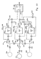
- any combination of one, two or three dope vessels 12, 152, 154 could be utilized to provide a mother dope from each vessel to each respective Dial-A-PorTM units where each respective dope would undergo thermal manipulation to produce a dope that would provide a specific predetermined pore size to each of the respective slot dies.
- At least one, and as many as all three of the dope vessels could contain dope formulated to produce a specific pore size, such dope being transported to the respective slot die, but by passing each of the respective Dial-A porTM units.
- any two of the Dial-A-PorTM units could be by passed by receiving dope directly from vessels containing dope formulated to produce a specific pore size for delivery to two of the slot dies, with the third slot die receiving dope from a vessel containing a mother dope, processed through one of the Dial-A-PorTM units to deliver dope for providing any one of the plurality of predetermined pore sizes at the third slot die.
- pore size specific preformulated dope could be delivered to one slot die by bypassing the Dial-A-PorTM unit, and dope fiom a single mother batch dope in one vessel could be processed through the other two Dial-A-PorTM units to deliver specific pore size producing dope to the other two slot dies.
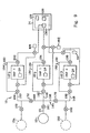
- one vessel could provide a mother dope to one Dial-A-PorTM unit 140 for thermal manipulation to a specific temperature to produce a specific pore size then deliver the so manipulated dope to two slot dies 128, 130 by providing a system 260 including a split transportation means 210 having branches 212, 214, connected to slot dies 129, 130, respectively.
- the support material 102 having first 104 and second 106 sides is impregnated with the first dope 108 from the appropriate dope source by any of a variety of techniques, e.g., roll coating, spray coating, slot die coating, and the like, with slot die pressure impregnating being presently preferred, to substantially completely impregnate the support material 102 with the first dope 108.
- complete impregnation of the support material means that all fibers of the support material are completely surrounded by liquid dope and that no portion of the support material is not covered by liquid dope and that no portion of the support material protrudes from the center zone into either the second or third zones in the finished three-zone membrane.
- the second 110 and third 116 dopes (see Figure 5) provided from appropriate dope sources, including the same mother dope source, produce substantially identical pore sizes but produce a different pore size than the first dope 108, provided from the appropriate source, including the same mother dope source of the second and third dopes.
- the second 110 and third 116 dopes provided from appropriate dope source, including the same mother dope source produce a different pore size as well as each producing a different pore size from the first dope 108 provided from an appropriate dope source, including the same mother dope source. It is possible to have any pore size from the largest to the smallest in any of the three zones and in any order.
- the middle zone 120 (as illustrated in Figure 7) of the microporous membrane 101 should have an average pore size which is at least about twenty percent (20%) greater, preferably at least about fifty percent (50%) greater, more preferably at least about 100% greater, and most preferably at least about 120% greather, than the average pore size of at least one of the upper zone 122 and lower zone 124 of the membrane and preferably both the upper and lower zones.
- the pores formed in the middle zone 120 have an average size of about ten (10) microns or less and the average pore size will preferably range from about 0.5 microns to about two (2) microns, more preferably from about 0.1 to about one (1.0) microns.
- the middle zone 120 has a pore size distribution which is preferably quite narrow in range, although this is not essential for satisfactory performance.
- the middle zone 120 should be as thin as possible so long as it provides sufficient structural strength and embeds the support material 102 such that, presently preferably, no fibers of the support material protrude from the middle zone 120 into either the upper 122 or the lower 124 zone.
- some strands/fibers of the support material 102 are contiguous with or slightly protrude into at least the one of the other two zone 122, 124 formed from a tight dope or coating solution or into both zones 122, 124 when both zones are formed from a tight dope.
- some strands/fibers of the support material 102 are contiguous with or slightly protrude into the other two zone 122, 124.
- middle zone in which at least some of the scrim is not completely encapsulated within the middle zone may be advantageous in that the thickness of the middle zone will be kept to a minimum, thus, resulting in a thinner overall finished membrane.
- the thichness of the middle zone will typically range from about fifty (50) microns to about one hundred fifty (150) microns and preferably from about seventy-five (75) microns to about one hundred (100) microns or whatever dope volume is necessary to substantially impregnate the scrim being impregnated at any specific time.
- the upper 122 and the lower 124 zones of the microporous membrane 101 possess pores which have a size providing the desired filtration efficiency or particle removal.
- the average size of the pores of the upper zone and the lower zone will be about one (1) micron or less, and can typically range from about 0.01 microns to about one (1) microns. More preferably, the average size of the pores of each zone will range from about 0.2 microns to about 0.5 microns. This zone microporous membrane is preferably narrow.
- the average pore size of the upper zone is substantially the same as the average pore size of the lower zone. By “substantially the same,” it is meant that the average pore size of the upper zone does not differ from that of the lower zone, and vice versa, by more than about twenty-five (25%) percent.
- the upper and the lower zones have substantially the same thickness so as to provide geometric symmetry around the central axis of the membrane. These zones should be as thin as possible in order to minimize the pressure drop across the reinforced, three-zone microporous membrane while being sufficiently thick to yield desired particulate removal.
- the individual thickness of each of the upper and lower zones will generally range from about twenty-five (25) microns to about one hundred (100) microns, preferably from about thirty-five (35) microns to about sixty (60) microns.
- the overall thickness of the reinforced, continuous, monolithic, geometrically symmetrical, microporous filtration membrane that would be produced by the system and method of the present disclosure will generally not exceed about ten (10) mils.
- the geometric symmetry of the microporous membrane produced under the systems and methods of the present application should minimize mechanical strains, reduce the likelihood of zone/layer separation of the three-zone membrane and generally improve the structural integrity of the three-zone membrane.
- These features are particularly important to fan-fold pleated cartridge arrangements, where both sides of the microporous membrane are expected to bend equally well around the neutral (unyielding) axis of the reinforcing scrim. Such bending should result in an equal distribution of tension and compression form in the pleat crests and troughs, such that neither side is burdened with an excessive tension or compression load, which would increase the possibility of damage and/or breech failure of the membrane at the pleat area.
- the unique thin cross-section, on both sides, of the three-zone membrane that would be produced using the systems methods of the present application should provide an advantage, in that the tension and compression forces should be minimized as the absolute radius from the center of the reinforcement to the outside surface of the three-zone membrane is minimized.
- the thickness of one of the upper or the lower zone could be considerably thicker than the other and still be within the teachings of the systems and methods of the present disclosure.
- the reinforced microporous three-zone membrane may be rolled and stored for use under ambient conditions. It will be understood that the reinforced, three-zone microporous membrane produced in accordance with the systems and methods of the present disclosure may be formed into any of the usual commercial forms, such as, for example, discs or pleated cartridges.
- the reinforced, three-zone microporous membrane is sanitized or sterilized by autoclaving or hot water flushing.
- the reinforced, three-zone microporous membrane produced by the systems and methods of the present disclosure should prove resistant to this type treatment, particularly when a hydrolytically stable nylon is used as described hereinabove, and retains its structural integrity in use under such conditions.
- the reinforced, three-zone microporous membrane produced by the systems and methods of the present disclosure should be easy to handle and readily formed into convoluted structures, e.g. pleated configurations. By reason of its improved flow characteristics, it should be capable of being employed directly in existing installations, without pumping modifications. Specifically, due to the improved flow rate, the existing pumps should actually operate at lower loads and thus would most likely have longer useful lives.
- the reinforced, three-zone filtration membrane produced in accordance with the systems and methods of the present disclosure should be characterized by unexpectedly high flow rates for a given differential pressure and also characterized by durability, strength, uniformity, lack of pinholes and bubble defects.
- the preferred membranes could be used with either side of the membrane facing upstream.
- the utilization of the original Dial-A-PorTM unit, as illustrated in Figure 3, has undergone considerable evolution since the development of the initial Dial-A-PorTM unit shown in Figure 3.
- the system 310 of Figure 3 included an independent metering pump 24 operatively positioned prior to the Dial-A-PorTM unit including the thermal manipulation means 26, 32 for pumping the dope from the vessel 12 through the various thermal manipulation means and to reservoirs.
- the reservoirs were then operatively connected to a specific die, as illustrated in Figure 5.
- the thermally manipulated dope was then moved from the reservoir to each respective die utilizing a metering pump to controllably deliver the dope to the respective die at the required pressure for applying the thermally manipulated dope to the scrim.
- one key to successfully operating the multiple Dial-A-PorTM system 10 of the present application is to provide sufficient pressure or force to move the dope to and through the Dial-A-PorTM units, regardless of the pressure source or dope moving means, and to specifically control the amount of dope delivered to each die.
- one presently preferred multiple Dial-A-PorTM unit 10 includes the vessel 12 being pressurized to a sufficiently high pressure, presently preferably, about forty-five (45) psig.
- the dope is moved from the storage vessel to and through each specific Dial-A PorTM unit(s) 25, 140, 142 via the pressure on the vessel.
- the thermally manipulated dope moves by the pressure to the inlet of a flow control valve, a metering pump or other precision flow control device, such as, for example, the presently preferred metering pump available from Roper, Pump Company, model No.
- the metering pumps 400, 402, 404 are effective to controllably deliver the appropriate amount of the thermally manipulated dope to the respective dies 126, 128, 130 at the appropriate rate.
- the metering pumps or the flow control devices are specified and selected based upon the precision flow control requirements for a specific application.
- each die has its own flow control device or metering pump 400, 402, 404.
- the flow control devices or metering pumps 400, 402, 404 control the deliver of the thermally manipulated dope to each of the dies 126, 129, 130, respectively, with the desired amount of thermally manipulated dope for application to the scrim needed to properly form the desired three phase, reinforced, microporous membrane at the dope processing site 14.
- One of the many possible alternatives to this specific system arrangement or configuration includes operatively positioning valves between each metering pump and each die for diverting the thermally manipulated dope from the dies to a waste container 410, 412, 414 or back to a previous location in the process, such as, for example, prior to or after the diversion valves 192, 196, 200.
- one or multiple storage vessels are pressurized to about forty-five (45) psig for moving the dope from the vessel to one, two or three Dial-A-PorTM units under sufficient pressure to move the thermally manipulated dope to the inlet of a flow control or metering pump 400, 402, 404.
- the metering pump for each die then controllably delivers the thermally manipulated dope to each die at a rate appropriate for each of the zones of the specific three-zone reinforced microporous membrane being produced.
- a metering pump can be positioned with each of the Dial-A-PorTM units, similar to the original Dial-A-PorTM unit of Figure 3, and provide the pressure or force necessary to move the thermally manipulated dope all the way from the vessels) 12, 152, 154 to each die 126, 128, 130 without the incorporation of any other flow or metering pumps between each Dial-A-PorTM unit and the respective die (see Figure 8).
- Dial-A-PorTM unit(s) will be subjected to the higher pressures required to provide the thermally manipulated dope to each die and, thus, the specification for each of the components of the Dial-A-PorTM unit(s) would most likely require higher cost components than would the system components using the presently preferred method of moving the dope from the vessel through the Dial-A-PorTM under pressure to the inlet of metering pumps for application to the scrim, as is presently preferred.
- FIG 10. Another possible alternative multiple Dial A-PorTM system is illustrated in Figure 10.
- the flow control pumps or metering pumps 400, 402 and 404 and the recirculation systems and waste collection vessel system of Figure 8 are utilized, but the metering pumps of Figure 3 are replaced by fluid transport pumps (not shown) which essentially replace the pressure provided by pressurizing the vessel 12 described above.
- the fluid transport pumps are used to move the dope from the storage vessel, which must be under sufficient pressure to move the dope from the vessel to the inlet of the fluid transport pump, through the Dial A PorTM units to the individual flow control units, such as, for example, a flow control valve or metering pumps for each die.
- This alternative system has several disadvantages. If a flow control valve is utilized, then the Dial A PorTM units would be subjected to the higher pressures required at the dies and a more complicated flow control system would be required to meter the flow to the dies. If the metering pumps are inserted between the Dial-A-PorTM units and the dies, the system will become more complicated in that a control system would be required to balance the pressures between the two pumps in series.
- An additional possible alternative of many possible alternatives would be to position one fluid transport pump 450 between the primary storage vessel and the fluid transportation system 144.
- this alternative system only one fluid transport pump 450 would be used to move the dope from the vessel to and through the Dial-A PorTM unit(s) to the inlet port of one, two or all three of the metering pumps or flow control valves positioned between each Dial-A-PorTM unit(s) and its respective die.
- one vessel could provide a mother dope to one Dial-A-PorTM unit 140 for thermal manipulation to a specific temperature to produce a specific pore size then deliver the so manipulated dope to the two slot dies 126, 128 via a system 260 including a split transportation means 210 having branches 213, 214, operatively connected to slot dies 126, 128, respectively. It is understood that the flow to each die must be controlled in some manner, as discussed above.
- the systems of the present disclosure can be adapted to provide for the manufacture of a plurality of possible three zone, reinforced microporous membrane.
- One key is that whatever means are utilized for moving the dope from the pressurized storage vessel(s) through one, two or three Dial-A-PorTM units must be effective to provide a sufficient volume of the thermally manipulated dope either to the inlet of a flow control device, such as, for example, a flow control valve or a metering pump for controlling the amount of thermally manipulated dope to be delivered to each die or must be effective to controllably deliver sufficient amounts of the thermally manipulated dope directly from the storage vessel to and through the one, two or three Dial-A-PorTM units to each individual die so as to enable sufficient dope to be applied to the scrim from each die during the manufacturing process at the dope processing site.
- a flow control device such as, for example, a flow control valve or a metering pump for controlling the amount of thermally manipulated dope to be delivered to each die or must
- the presently preferred system for both a single and a multiple Dial-A-PorTM system includes pressurizing the vessel to about forty-five (45) psig, which has proven sufficient to move the dope from one vessel through three Dial-A-PorTM units to three metering pumps, one metering pump between each Dial-A-PorTM unit and each die, and then utilizing the metering pumps to control the transfer of the thermally manipulated dope to each die for application of the dope to the scrim at the dope processing site.
- 45 forty-five
- the following examples are directed to the production of reinforced, three-zone microporous membrane including the preparation of a mother dope, thermal manipulation of the mother dope to produce a dope that when applied to a scrim by dope application mechanism or means provides any one of a plurality of possible specific pore sizes in a specific performance zone of the final microporous membrane, the delivery of the dope to a dope processing site and the application of the dope to form the membrane at the dope processing site resulting in a reinforced, three-zone microporous membrane.
- the dope is processed in a vessel to a maximum temperature of about 28°C, after the nylon is added to the mixture, which should result in a FAOP of about 196 psi and a IBP of about 149.3 psi.
- the storage vessel containing the above mother dope is operatively connected to the three separate Dial-A-PorTM unit for thermal manipulation of portions of the mother dope. Then the vessel is pressurized to approximately forty-five (45) psi with nitrogen, to move the dope from the vessel to each of the Dial-A-PorTM units, each Dial-A-Por unit is connected to precision metering pumps to feed precise amounts of treated dope to one of each of the three coating dies.
- Each Dial-A-PorTM unit or system for thermal manipulation (elevation of the dope temperature to a predetermined temperature) is activated and the target temperature is set to the specific target temperature for the dope to be delivered to each slot die.
- dope valves are opened and dope is moved by pressure from the sealed vessel through each Dial-A-PorTM system, then on to precision metering pumps and the respective coating dies.
- each thermally manipulated dope is delivered preferably via one precision metering pump described above from a respective Dial-A-PorTM unit to the selected one of the three slot dies of the apparatus at the dope processing site as described above and in U.S. Patent Applications SN/03/040,979 and 09/040,816 to produce a geometrically symmetric and pore size symmetric reinforced, three-zone membrane with an "open" (large pore size) scrim encapsulated center zone.
- non-woven Polypropylene bicomponent fiber web or scrim suitable for preparation of the reinforced, three-zone membrane (commercially available from Freudenberg under the tradename Viledon® , Grade # F02432), having a basis weight of nominally 30 gm/sq.meter is processed by the method taught in the 09/040,979 and 09/040,816 applications.
- the scrim is pre-treated with a mild Corona Discharge to enhance its wetability prior to being pressure impregnated.
- the larger pore size dope is provided from the Dial-A-PorTM unit operatively connected to the first slot die (impregnating die) and is used to pressure impregnate the scrim, with an impregnation weight of about seven (7) gm/sq.meter of Nylon solids.
- the nylon solids are provided from the dissolved nylon in the dope solution, which can be, for example, a fourteen and one-half (14.5) wt% nylon solution (approximately 50 grams of liquid dope per square meter), which is sufficient to impregnate and fill the void volume of the scrim, creating the first zone of large pore size dope integral with the supporting scrim.
- both sides of the pressure impregnated scrim are essentially simultaneously coated with substantially even layers of a smaller pore size dope received from the second and third Dial-A-PorTM units, respectively.
- the total coating weight delivered to the two sides is about thirty-seven (37) gm/sq.meter of Nylon solids in about a fourteen and one-half (14.5) wt% solution (approximately 260 grams of liquid dope per square meter), with the total being split between the two streams of dope feeding onto the two sides of the pressure impregnated scrim, so that both sides are substantially evenly coated with the two streams of dope which have been separately processed thorough their respective Dial-A-PorTM units to substantially the same end-point of maximum temperature for producing substantially equivalent small pore size membrane upon coating and quenching. These should create the second and third zones of the finished membrane from the small pore size dope.
- the grand total application of both dopes is, thus, approximately forty-four (44) gm/sq.meter Nylon solids.
- the thus coated three-zone structure is then quickly brought into contact with a Marinacco-style quench solution, which simultaneously quenches the three-zone structure from the outer surfaces of the small pore size dope, such that a continuous microporous membrane structure is formed.
- the quenched membrane is then washed, dried under X & Y direction dimensional restraint, and tested, in the usual manner.
- Zone Two A second three-zone membrane is prepared in nearly identical manner as in Example 1, with the exception that one of the coating sides of the pressure impregnated scrim (in this case, Zone Two) is coated with dope from it's respective Dial-A-PorTM unit which had been processed to substantially the same end-point of maximum temperature for producing substantially equivalent large pore size membrane as the dope processed from the Zone One (impregnating zone) Dial-A-PorTM and slot die combination. Zone Two is thus coated with approximately fifteen (15) gm/sq.meter Nylon solids from the large pore size dope produced by its respective Dial-A-PorTM units or alternatively having the Zone One Dial.-A-PorTM unit provide the same dope.
- the opposite side (Zone Three) is simultaneously coated with the approximately twenty-two (22) gm/sq.meter Nylon solids from small pore size received from the appropriate Dial-A-PorTM unit.
- the resultant finished membrane would achieve a continuous, substantially geometric symmetry wound the neutral axis of the reinforcing scrim, but have very different pore size attributes on both sides of the scrim. (i.e., Pore Size Asymmetric).
- Example 1 membrane produced in accordance with the systems and methods of the present disclosure should show a clearly improved flow rate over the standard (control) membrane as disclosed in those applications. It is believed that a similar membrane produced in accordance with the systems and methods of the present disclosure would also have a clearly improved flow rate over a standard (control membrane) of the same application.
- the raw water flow rate (Q, expressed as cc/min clean deionized water for a nominally forty-seven (47) mm test disc (13.5 cm 2 test area) under water pressure of 5 psid) should show about a twenty (20%) percent improvement, while the integrity, as measured by Initial Bubble Point, should be surprisingly increased by about six (6%) percent, for the same overall membrane thickness. This expected improvement potentially should provide a double benefit, these being improved clean water flow rate and improved integrity as measured by IBP.
- the increase in initial Bubble Point should be corroborated by both the increase in membrane Foam-All-Over-Point, and the decrease in the ASTM Mean Flow Pore size rating.
- the Example 2 membrane should provide a stunning improvement in flow rate over the standard (control) membrane as disclosed in those applications of about seventy-eight (78%) percent, while retaining almost the same integrity attributes in IBP and FAOP.
- the Mean Flow Pore (MFP) a more universally recognized method for mean pore size, of which FAOP is attempting to approximate, should show the expected difference: a larger mean flow pore is consistent with a higher flow rate, and this indicates that there is, by the flow averaging method, a wider distribution ofpore sizes in the Example 2 membrane if it were compared to a control membrane.
- Example 2 could illustrate another advantage to the membrane produced in accordance with the systems and methods of the present disclosure which is the ability to produce, in a single membrane, three separate zones of performance which, when oriented by decreasing pore size, can provide a novel, surprisingly thin section combination reinforced prefilter and final filter, having geometric symmetry, good integrity, and very high flow rates.
- the systems and methods of the present disclosure for producing reinforced, three-zone membrane should provide croporous membrane having markedly improved flow rates in filtration applications, for their pore size attributes, as compared to standard products now common in the membrane filtration industry.
- the relatively thin cross-sections of these three-zone membrane products should result in membrane cartridges having more surface area and even higher throughputs. This combination should translate into a higher value added product for the filtration customer.
- the resultant three-zone microporous membrane was composed of three zones that were continuously joined by the molecular entanglement of the polymers which occurred in the liquid state of the dope after each of the outer zone dopes was coated onto the dope of the central zone and prior to quenching. This is significantly different from the prior art lamination process wherein three separately formed membranes were quenched and then laminated together.
- the liquid to liquid mixing of the central zone liquid dope with each of the outer zones liquid dope, prior to quenching resulted in a three phase, reinforced, microporous membrane having a continuous polymer entanglement on the molecular level, as illustrated by the scanning electron photo micrographs.
- the actual following examples are directed to the production of reinforced, three-zone microporous membrane including the preparation of a mother dope, thermal of the mother dope to produce a dope that when applied to a scrim by dope application mechanism or means provides any one of a plurality of possible specific pore sizes in a specific performance zone of the final microporous membrane, the delivery of the dope to a dope processing site and the application of the dope to form the membrane at the dope processing site resulting in a reinforced, three-zone microporous membrane.
- a mother dope identified as Dope # 00B027, of about fourteen and one-half petcent (14.5%) by weight Nylon 66 (Monsanto Vydyne 66Z), about seventy-seven and four-tenths percent (77.4%) by weight Formic Acid and about eight and one-tenth percent (8.1%) by weight methanol, was produced by the method disclosed in U.S. Patent Nos. 3,876,738 and 4,645,602, the disclosure of each is herein incorporated by reference.
- the dope was processed in a vessel to a maximum temperature of about twenty-eight degrees (28°) C, after the nylon was added to the mixture. and allowed to mix as per the normal cycle. It was believed that the temperature control equipment which maintains the maximum temperature through this mother dope mix cycle was not as precise as the Dial-A-porTM system's temperature regulation; and may typically vary by as much as about ⁇ 0.5 degrees C or more. This will affect the ability to precisely replicate the characteristics of a given mother dope, even when the same formulation was repeated.
- a second small portion of the mother dope was cast, quenched, folded onto itself, then dried under restraint to produce a substantially identical sample as described above.
- This sample was wetted in a solution containing about sixty percent (60%) by weight Isopropyl Alcohol and about forty percent (40%) by weight deionized water.
- This solution has a lower surface tension than that of pure water, thus providing a reduction in capillary expulsion pressure needed to perform the Initial Bubble Point test.
- the approximate surface tension of the 60/40 IPA/H 2 O mix is about twenty-four (24) dyne/cm, where as the surface tension of pure DI water is about seventy-three (73) dyne/cm.
- the test was performed, and Initial Bubble Point pressure was recorded as about fifty-four (54) psig in Isopropyl Alcohol.
- the effective Initial Bubble Point of such a membrane would be about a factor of three times (3x) greater if tested in pure water, or about one-hundred-sixty-two (162) psig in pure water.
- such a nylon microporous membrane might be rated as nominally about 0.02 ⁇ to about 0.04 ⁇ in pore size. This was evidence that the mother dope, as formulated and produced for this example, had a very small pore size prior to being processed by each Dial-A-PorTM unit, and further processed into a three-zone microporous nylon membrane by a vertical casting apparatus at a dope processing site.
- the storage vessel containing the above mother dope was operatively connected to the three separate Dial-A-PorTM units for thermal manipulation of portions of the mother dope. Then, the vessel was pressurized to about forty-five (45) psi with nitrogen, to move the dope from the vessel to each of the Dial-A-PorTM units, each Dial-A-PorTM unit was operatively connected to a precision metering pump for transporting precise amounts of thermally manipulated dope to a respective one of each of the three coating dies.
- Each Dial-A-PorTM unit or system for thermal manipulation was activated and the target temperature was set to the specific target temperature for the dope to be delivered to each of the three slot dies.
- dope valves were opened and dope was moved under pressure from the sealed vessel through each Dial-A PorTM unit, then on to each precision metering pump and each respective coating die.
- the target maximum temperature was fifty-four degrees (54.0°) C to effect a relatively lower bubble point impregnation dope attribute, followed by cooling to about twenty-one degrees (21°) C, to effect a useful dope viscosity for impregnation and coating.
- the target maximum temperature was fifty-four degrees (54.0°) C to effect a relatively lower bubble point coating on the Membrane Zone Two side, which was substantially the same as the bubble point of the impregnation zone, followed by cooling to about twenty-one degrees (21°) C, to effect a useful dope viscosity for coating,
- the target maximum temperature was forty-five degrees (45.0°) C, to effect a relatively higher bubble point coating in the Membrane Zone Three side, followed by cooling to about twenty-one degrees (21°) C, to effect a useful dope viscosity for coating. Since the Membrane Zone Three side contains the relatively higher bubble point as compared to the (substantially equal) bubble points of the Membrane Zone One and Membrane Zone Two sides, the product produced for this example will be a geometrically symmetric, pore size asymmetric nylon microporous membrane.
- each thermally manipulated dope was delivered preferably via one precision metering pump described above from a respective Dial-A-PorTM unit to the selected one of the three slot dies of the apparatus at the dope processing site as described above and in U.S.
- Patent Applications SN/03/040,979 and 09/040,816 to produce a geometrically symmetric and pore size asymmetric reinforced, three-zone membrane with a first "open” (large pore size) scrim encapsulated center zone (Membrane Zone One), and one "open” (large pore size) outer zone on one of the sides of the scrim (Membrane Zone Two), and one "tight” (small pore size) outer zone (Membrane Zone Three) opposite the other outer zone.
- non-woven Polypropylene bicomponent fiber web or scrim suitable for preparation of the reinforced, three-zone membrane (commercially available from Freudenberg under the tradename Viledon®, Grade # F02432), having a basis weight of nominally 30 gm/sq.meter was processed by the method taught in the 09/040,979 and 09/040,816 applications.
- the scrim was pre-treated with a mild Corona Discharge to enhance its wetability before being pressure impregnated.
- the relatively larger pore size dope was provided from the Dial-A-PorTM unit operatively connected to the first slot die (or Membrane Zone One impregnating die) and was used to pressure impregnate the scrim, with an impregnation weight of about twelve and one-half (12.5) gm/sq.meter of Nylon solids.
- the nylon solids were provided from the dissolved nylon in the dope solution, which were, in this example, a fourteen and one-half (14.5) wt% nylon solution (about eighty-six and two-tenths, 86.2, grams of liquid dope per square meter), which was sufficient to impregnate and fill the void volume of the scrim, and leave a small excess of coating dope on the application side of the scrim creating the first zone of large pore size dope integral with the supporting scrim.
- both sides of the pressure impregnated scrim were essentially simultaneously coated with dope received from the other two slot dies, which was provided from their respective Dial-A-PorTM units, as described above.
- Membrane Zone Two was thus coated with about thirteen (13.0) gm/sq.meter Nylon solids from the large pore size dope produced by its respective Dial-A-PorTM unit.
- Membrane Zone Two was applied from the same side of the scrim as the impregnation die, i.e. both dies for Membrane Zone One and Membrane Zone Two (near) faced the same direction.
- Membrane Zone Two contained dope that was substantially the same bubble point as the impregnation zone (Membrane Zone One).
- the Membrane Zone Two application weight was lowered relative to Membrane Zone Three, in order to maintain geometric symmetry.
- the opposite side was substantially simultaneously coated with the about eighteen and one-half (18.5) gm/sq.meter Nylon solids from the small pore size dope received from its respective Dial-A-PorTM unit.
- the total coating weight from all dies thus applied to the scrim was about forty-four (44) gm/sq.meter.
- the resultant finished membrane achieved a continuous, substantially geometric symmetry around the neutral axis of the reinforcing scrim, but had very different pore size attributes on both sides of the scrim. (i.e., Pore Size Asymmetric).
- FFBP 60/40 IPA wet
- Thickness A process gage was used to measure three points across the width of a short length of an in-proeess sample. This sample was taken from the wet-as-cast, and DI water washed membrane, in the V/C/L production area. The sample was dried under restraint in crossweb and machine direction. Three points spanning the crossweb sample are tested with the process gage, and used to calculate an average which was reported. The wet-as-cast roll then proceeded to the drying process.
- a precision water flow meter was mounted downstream of a one-hundred-forty-two (142) mm diameter filter disc housing (Millipore sanitary design, Millipore catalogue No. 302200). The housing was directly tapped on the inlet side and the outlet side so that a differential pressure gage could be used to measure the instantaneous differential pressure across the membrane. A precision pressure transducer was connected across the housing. Fresh filtered 1 megohm D.I. water under pressure, nominally about thirty (30) psi, was plumbed into the housing with means to regulate flow rate. By varying the clean water flow rate through the housing and measuring the differential pressure at each flow rate, a pressure vs. flow rate graph was constructed.
- Coulter Mean Flow Pore Size The Coulter Porometer II from Coulter instruments was used to measure the Mean Flow Pore in accordance with the instrument manufacturer's instructions, using Porofil wetting fluid, and a thirty-seven (37) mm housing. Three samples were tested, and the average value was reported.
- a second mother dope having the same formulation as described in Actual Example 1 above was prepared, under about the same conditions.
- the dope was characterized as before, and the results are also reported in Table 1. Within the limits of common cause error, the dope was a replicate of the Example 1 dope.
- a three zone, geometrically symmetric, pore size asymmetric nylon microporous membrane was prepared under substantially the same conditions as described in Actual Example 1. The only substantive difference was the selection of the specific target maximum temperatures for the three separate Dial-A-PorTM units. These specific target temperatures were as follows. For Membrane Zone One (impregnation), the target maximum temperature was fifty-seven degrees (57.0°) C. For Membrane Zone Two (near side), the target maximum temperature was also fifty-seven degrees (57.0°) C. For Membrane Zone Three (opposite side), the target maximum temperature was fifty degrees (50.0°) C.
- the resultant three-zone, geometrically symmetric, pore size asymmetric nylon microporous membrane was tested and reported in Table 1.
- Table 1 For illustration, the three-zone asymmetric pore structure of this Actual Example 2 membrane is shown in cross section by Scanning Electron micrograph in Figures 13a-b.
- the resulting membrane has a substantially larger pore size rating and a higher clean water flow rate than the membrane of Actual Example 1. This was as expected, considering the relatively higher maximum Dial-A-PorTM unit target temperatures used in the processing of this membrane.
- a third mother dope having the same formulation as described in Actual Example One (1) was prepared, under substantially the same conditions as Actual Examples One (1) and Two (2).
- the dope was characterized as before, and the results are reported in Table 1. Within the limits of common cause error, the dope was a replicate of the Example One dope.
- a three-zone, geometrically symmetric, pore size asymmetric nylon microporous membrane was prepared under substantially the same conditions as described in Actual Example One. The only substantive differences are the selection of the specific target maximum temperatures for the three separate Dial-A-PorTM units. These specific target temperatures are as follows. For Membrane Zone One (impregnation), the target maximum temperature was sixty-two degrees (62.0°) C. For Membrane Zone Two (near side), the target maximum temperature was also sixty-two degrees (62.0°) C. For Membrane Zone Three (opposite side), the target maximum temperature was fifty-four degrees (54.0°) C.
- a plurality of pore sizes can be effectively produced and placed in specific zones of a three-zone, geometrically symmetric nylon microporous membrane. It is believed that anyone of ordinary skill in the art can effectively design pore size symmetric or asymmetric structures, gradient density structures, and any one of many application specific structures while maintaining geometric symmetry by manipulating the pore sizes, coating weights, and application temperatures of the zones disclosed in these actual examples. Other structures are also believed easily realized, having controlled asymmetry in geometry as well.
- the above described actual examples are taken from real production data of salable membrane product.
- the present actual examples are intended to demonstrate reduction to practice of the concept of using three independent Dial-A-PorTM units fed from a single mother dope to produce a three-zone, reinforced membrane.
- Each Dial-A-PorTM unit was operatively connected to a unique Zone coating die, and independently processed the same mother dope to effect different Membrane Zone characteristics, as desired for the production of many possible unique products from the same dope formulation.
- the production of a plurality of possible pore size microporous membranes has now been achieved, using the above described production equipment.
- the pore size has been simply and effectively "dialed in” on the production equipment to produce unique performance zones in each of the three zones of the three-zone reinforced membrane through temperature and zone coating weight manipulation.
- the systems and methods of the present disclosure for producing reinforced, three-zone membrane provided microporous membrane having markedly improved flow rates in filtration applications, for their pore size attributes, as compared to standard products now common in the membrane filtration industry.
- the relatively thin cross-sections of these three-zone, membrane products produced membrane cartridges having more surface area and even higher throughputs than prior products. These products clearly translated into a higher value added product for the filtration customer.
- the systems and methods of manufacturing three-zone, reinforced microporous membrane has produced a membrane having a minimum functional thickness and maximum throughput at minimal pressure drops, high integrity and was economically produced in any one of a plurality of different pore sizes in each of the three zones.
- the systems and methods for manufacturing three-zone, reinforced microporous membranes has eliminated the necessity for preparing at least one dope batch according to individual unique formulations for each pore size, thus resulting in significant cost savings and flexibility in the usage of dope batches.
- the three-zone membrane produced by the system and methods of the present application will have a discontinuous pore structure with a continuous entanglement of the separate layers/zones of polymer such that the continuous, reinforced, microporous membrane produced is structurally integral.
- the membrane may be treated in accordance with U.S. Patent No. 4,473,474, the disclosure of which is herein incorporated by reference, to produce a cationically charge modified microporous membrane particularly suitable for the filtration of parenteral or biological liquid or, in accordance with U.S. Patent No. 4,473,475, the disclosure of which is incorporated herein by references to produce cationically charged modified microporous membrane particularly suitable for the filtration of high purity water required in the manufacture of electronic components.
- nylon 66 is a member of a group of polymers that are capable of being processed into microporous membrane via the phase inversion process
- the nature of this process is such that there is a strong probability that the methods and systems of the present disclosure will be applicable to these other polymers as well, including, but not limited to, nylon 66, nylon 46, nylon 6, polysulfone, polyethersulfone, polyvinylidenediflouride (PVDF) and other ternary phase inversion polymers that form microporous structures through the phase inversion process.
- PVDF polyvinylidenediflouride
Claims (29)
- System zur Herstellung einer drei Zonen umfassenden mikroporösen Membran aus einem ternären Phaseninversions-Polymer-Ausgangs-Dopemittel, wobei das System folgendes umfasst:wenigstens ein Gefäß zur Aufnahme des Dopemittels,eine Dapemittel-Verarbeitungsstation,wenigstens eine Druckeinrichtung, die betriebsmäßig mit dem wenigstens einen Gefäß und der Dopemittel-Verarbeitungsstation verbunden ist, wobei die wenigstens eine Druckeinrichtung geeignet ist, das Dopemittel aus dem wenigstens einem Gefäß zur Dopemittel-Verarbeitungsstation zu bewegen,ein Dopemittel-Transportsystem, das betriebsmäßig mit dem wenigstens einen Gefäß und der Dopemittel-Verarbeitungsstation verbunden ist, wobei das Dopemittel-Transportsystem geeignet ist, das Dopemittel von dem wenigstens einen Gefäß zu der Dopemittel-Verarbeitungsstation zu fördern,wenigstens eine Temperatur-Beeinflussungseinrichtung, die betriebsmäßig mit dem wenigstens einen Gefäß und der Dopemittel-Verarbeitungsstation verbunden ist, wobei die wenigstens eine Temperatur-Beeinflussungseinrichtung geeignet ist, das Dopemittel zu transformieren, um eine Vielzahl von mikroporösen Membranen zu erzeugen, die gewünschte Porengrößen besitzen, undwenigstens drei Dopemittel-Auftrageinrichtungen, die an der Dopemittel-Verarbeitungsstation arbeiten und betriebsmäßig mit der wenigstens einen Temperatur-Beeinflussungseinrichturtg verbunden sind, wobei die wenigstens drei Dopemittel- Auftrageinrichtungen geeignet sind, das Dopemittel an der Dopemittel-Verarbeitungsstation aufzutragen.
- System nach Anspruch 1, das weiterhin folgendes umfasst:wenigstens eine zweite Temperatur-Beeinftussungseinrichtung, die betriebsmäßig mit dem wenigstens einen Gefäß, dem Dopemittel-Transportsystem und wenigstens einer der drei Dopemittel- Auftrageinrichtungen verbunden ist, wobei die zweite Temperatur-Beeinflussungseinrichtung geeignet ist, das Dopemittel für ein Aufbringen an der Dopemittel-Verarbeitungsstelle in irgend eines einer Vielzahl von Dopemitteln zu transformieren, die unterschiedliche mögliche Porengrößen erzeugen.
- System nach Anspruch 2, das weiterhin folgendes umfasst:wenigstens eine dritte Temperatur-Beeinflussungseinrichtung, die betriebsmäßig mit dem wenigstens einen Gefäß, dem Dopemittel-Transportsystem und wenigstens einer weiteren der drei Dopemittel- Auftrageinrichtungen verbunden ist, wobei die dritte Temperatur-Beeinflussungseinrichtung geeignet ist, das Dopemittel für ein Aufbringen an der Dopemittel-Verarbeitungsstelle in irgend eines einer Vielzahl von Dopemitteln zu transformieren, die unterschiedliche mögliche Porengrößen erzeugen.
- System nach Anspruch 1, das weiterhin folgendes umfasst:wenigstens eine zweite und eine dritte Temperatur-Beeinflussungseinrichtung, die jeweils betriebsmäßig mit dem wenigstens einen Gefäß und wenigstens zwei der drei Dopemittel- Auftrageinrichtungen verbunden sind, wobei die Temperatur-Beeinflussungseinrichtungen geeignet sind, das Dopemittel, das von dem wenigstens einem Gefäß zu den zweiten und dritten Temperatur-Beeinflussungseinrichtungen gepumpt wird, für ein Aufbringen an der Dopemittel-Verarbeitungsstelle in irgend eines einer Vielzahl von Dopemitteln zu transformieren, die unterschiedliche mögliche Porengrößen erzeugen.
- System nach Anspruch 1, das weiterhin folgendes umfasst:wenigstens ein zweites Gefäß, das betriebsmäßig mit den Dopemittel-Transporteinrichtungen verbunden ist und ein ternäres Phaseninversions-Polymer-Dopemittel enthält.
- System nach Anspruch 5, das weiterhin folgendes umfasst:wenigstens ein drittes Gefäß, das betriebsmäßig mit dem Dopemittel-Transportsystem verbunden ist und ein ternäres Phaseninversions-Polymer-Dopemittel enthält.
- System nach Anspruch 1, das weiterhin folgendes umfasst:Bypasseinrichtungen, die betriebsmäßig mit der wenigstens einen Temperatur-Beeinflussungseinrichtung verbunden sind, wobei die Bypasseinrichtungen geeignet sind, das Dopemittel, das von dem wenigstens einen Gefäß zu der Dopemittel-Verarbeitungsstation transportiert wird, so zu leiten, dass das Dopemittel von der wenigstens einen Temperatur-Beeinflussungseinrichtung nicht vor seiner Abgabe an die Dopemittel-Verarbeitungsstation behandelt wird.
- System nach Anspruch 2, das weiterhin folgendes umfasst:Bypasseinrichtungen, die betriebsmäßig zumindest mit der zweiten Temperatur-Beeinflussungseinrichtung verbunden sind, wobei die Bypasseinrichtungen geeignet sind, das Dopemittel von dem wenigstens einen Gefäß zu der Dopemittel-Verarbeitungsstation so zu leiten, dass das Dopemittel von der wenigstens zweiten Temperatur-Beeinflussungseinrichtung nicht vor seiner Abgabe an die Dopemittel-Verarbeitungsstation bearbeitet wird.
- System nach Anspruch 3, das weiterhin folgendes umfasst:Bypasseinrichtungen, die betriebsmäßig zumindest mit der dritten Temperatur-Beeinflussungseinrichtung verbunden sind, wobei die Bypasseinrichtungen geeignet sind, das Dopemittel von dem wenigstens einen Gefäß zu der Dopemittel-Verarbeitungsstation so zu leiten, dass das Dopemittel durch die wenigstens dritte Temperatur-Beeinflussungseinrichtung nicht vor seiner Abgabe an die Dopemittel-Verarbeitungsstation bearbeitet wird.
- System nach Anspruch 1, bei dem die Temperatur-Beeinflussungseinrichtung weiterhin folgendes umfasst:Heizeinrichtungen, die betriebsmäßig in der wenigstens einen Temperatur-Beeinflussungseinrichtung angeordnet sind, wobei die Heizeinrichtungen geeignet sind, die Temperatur zumindest eines Teils des Dopemittels auf einen Wert zu erhöhen, der innerhalb eines Bereiches von ungefähr ± 0,2 °C einer vorbestimmten Temperatur entspricht, wobei die vorbestimmte Temperatur aus einer geeichten Charakterisierungskurve ausgewählt ist, die die Relation zwischen dem in Verarbeitung befindlichen Dopemittel und der sich ergebenden Porengröße in wenigstens einer Zone der drei Zonen umfassenden mikroporösen Membran beschreibt.
- System nach Anspruch 10, bei dem die Temperatur-Beeinflussungseinrichtung weiterhin folgendes umfasst:Kühleinrichtungen, die betriebsmäßig mit der wenigstens einen Temperatur-Beeinflussungseinrichtung verbunden sind, wobei die Kühleinrichtungen geeignet sind, das Dopemittel nach dem Verarbeiten durch die Temperatur-Beeinflussungseinrichtung auf eine Temperatur derart abzukühlen, dass das Dopemittel eine für eine Verarbeitung durch irgendeine der drei Dopemittel-Auftrageinrichtungen ausreichende Viskosität besitzt, um eine mikroporöse Phaseninversionsmembran zu erzeugen.
- System nach Anspruch 11, bei dem die Heizeinrichtungen weiterhin folgendes umfassen:erste Heizeinrichtungen, die betriebsmäßig mit der Pumpe verbunden sind, wobei die ersten Heizeinrichtungen geeignet sind, die Temperatur zumindest eines Teils des Dopemittels auf einen Wert in einem Bereich von ungefähr 2 °C unterhalb der vorbestimmten Temperatur anzuheben, undzweite Heizeinrichtungen, die betriebsmäßig mit den ersten Heizeinrichtungen verbunden sind, wobei die zweiten Heizeinrichtungen geeignet sind, die Temperatur zumindest eines Teils des Dopemittels auf eine Temperatur weiter anzuheben, die nicht höher ist, als dass sie in einem Bereich von ungefähr ± 0,2 °C bezüglich der vorbestimmten Temperatur liegt.
- System nach Anspruch 12, bei dem die zweiten Heizeinrichtungen die Temperatur des Dopemittels weiterhin auf eine Temperatur erhöhen, die nicht höher ist, als dass sie in einem Bereich von ungefähr ± 0,15 °C bezüglich der vorbestimmten Temperatur liegt.
- System nach Anspruch 1, das weiterhin folgendes umfasst:Dicken-Steuereinrichtungen, die betriebsmäßig zwischen dem Gefäß, das das ternäre Phaseninversions-Polymer enthält, und der Dopemittel-Verarbeitungsstation positioniert sind, wobei die Dicken-Steuereinrichtungen geeignet sind, die Dicke des Dopemittels während seiner Aufbringung durch die Auftrageinrichtungen zu steuern.
- System nach Anspruch 1, das weiterhin folgendes umfasst:Gewichts-Steuereinrichtungen, die betriebsmäßig zwischen dem Gefäß, das das ternäre Phaseninversions-Polymer enthält, und der Dopemittel-Verarbeitungsstation positioniert sind, wobei die Gewichts-Steuereinrichtungen geeignet sind, das Beschichtungsgewicht des Dopemittels während seiner Aufbringung durch die Auftrageinrichtungen zu steuern.
- System nach Anspruch 1, bei dem eine Dopemittel-Verarbeitungsstation betriebsmäßig mit dem wenigstens einen das Dopemittel enthaltenden Gefäß verbunden ist.
- Verfahren zur Herstellung einer drei Zonen umfassenden, mikroporösen Membran aus einem ternären Phaseninversions-Polymer-Dopemittel, wobei das Verfahren folgende Schritte umfasst:Zubereiten eines ternären Phaseninversions-Polymer-Ausgangs-Dopemittels in wenigstens einem Gefäß, um eine Auflösung und eine Gleichgewichtsmischung des Polymers, des Lösemittels und des Nichtlösemittels zu erzielen,Halten des Ausgangs-Dopemittels in dem wenigstens einem Gefäß bei einer Temperatur, die ausreicht, um das zubereitete Dopemittel nach dem Abkühlen von der Zubereitungstemperatur zu stabilisieren und aufrecht zu erhalten,Transportieren des zubereiteten Dopemittels zu einer Dopemittel-Verarbeitungsstation, die zumindest drei Dopemittel-Auftrageinrichtungen umfasst,thermisches Beeinflussen des Ausgangs-Dopemittels, das von dem wenigstens einen Gefäß transportiert wird, unter Verwendung wenigstens einer Temperatur-Beeinflussungseinrichtung zur Erzeugung einer mikroporösen Membran mit einer Porengrösse aus einer Vielzahl von verschiedenen mögtichen Porengrössen, undAufbringen eines vorbestimmten der thermisch beeinflussten Dopemittel auf einen Gitterstoff an der Dopemittel-Verarbeitungsstation, um eine verstärkte, drei Zonen umfassende mikroporöse Membran zu erzeugen.
- Verfahren nach Anspruch 17, das weiterhin folgende Schritte umfasst:unter Verwendung einer zweiten Temperatur-Beeinflussungseinrichtung erfolgendes, thermisches Beeinflussen des Ausgangs-Dopemittels, das aus dem wenigstens einen Gefäß gefördert wird, um ein vorbestimmtes Dopemittel aus einer Vielzahl von Dopemitteln zu erhalten, die unterschiedliche mögliche Porengrössen erzeugen, undAufbringen des vorbestimmen Dopemittels aus der Vielzahl von Dopemitteln, die unterschiedliche mögliche Porengrössen erzeugen, das von jeder der beiden Temperatur-Beeinflussungseinrichtungen erhalten wird, auf einen Gitterstoff, auf den ein thermisch beeinflusstes Dopemittel von einer der beiden Temperatur-Beeinflussungseinrichtungen aufgebracht worden ist, um eine verstärkte, drei Zonen umfassende mikroporöse Membran zu erzeugen.
- Verfahren nach Anspruch 18, das weiterhin folgende Schritte umfasst:unter Verwendung einer dritten Temperatur-Beeinflussungseintichtung erfolgendes, thermisches Beeinflussen des Ausgangs-Dopemittels, das aus dem wenigstens einen Gefäß gefördert wird, um ein vorbestimmtes Dopemittel aus einer Vielzahl von Dopemitteln zu erhalten, die unterschiedliche mögliche Porengrössen erzeugen, undAufbringen des vorbestimmen Dopemittels aus einer Vielzahl von Dopemitteln, die unterschiedliche mögliche Porengrössen erzeugen, das von jedem der drei Temperatur-Beeinflussungseinrichtungen erhalten wird, auf einen Gitterstoff an der Dopemittel-Verarbeitungsstation, um eine verstärkte, drei Zonen umfassende mikroporöse Membran zu erzeugen.
- Verfahren nach Anspruch 19, das weiterhin folgende Schritte umfasstVorsehen wenigstens eines zweiten Gefässes, das ein ternäres Phaseninversions-Polymer-Ausgangs-Dopemittel enthält, wobei das Dopemittel einer Mischungstemperatur ausgesetzt worden ist, die ausreicht, um eine Lösung und Gleichgewichtsmischung des Polymers, des Lösemittels und des Nichtlösemittels zu bewirken, wobei das Gefäß und das in ihm enthaltene Dopemittel nach dem Herabkühlen von der Mischungstemperatur auf einer Temperatur gehalten werden, die ausreicht, um die Mischung zu stabilisieren und aufrecht zu erhalten.
- Verfahren nach Anspruch 19, das weiterhin folgende Schritte umfasst:Vorsehen wenigstens eines dritten Gefäßes, das ein ternäres Phaseninversions-Polymer-Ausgangs-Dopemittel enthält, wobei das Dopemittel einer Mischungstemperatur ausgesetzt worden ist, die ausreicht, um eine Lösung und eine Gleichgewichtsmischung des Polymers, des Lösemittels und des Nichtlösemittets zu bewirken, wobei das Gefäß und das in ihm enthaltene Dopemittel nach dem Herunterkühlen von der Mischungstemperatur auf einer Temperatur gehalten werden, die ausreicht, um die Mischung zu stabilisieren und aufrecht zu erhalten.
- Verfahren nach Anspruch 20, bei dem während des thermischen Behandfungsschrittes die Temperatur des Ausgangs-Dopemittels inkrementell auf eine Temperatur angehoben wird, die nicht höher ist, als dass sie innerhalb eines Bereiches von ± 0,15 °C bezüglich der vorbestimmten Temperatur liegt.
- Verfahren nach Anspruch 17, bei dem das Ausgangs-Dopemittel weiterhin folgende Bestandteile umfasst:ein Phaseninversions-Membran-Polymer, ein Lösemittel und ein Nichtlösemittel in Lösung.
- Verfahren nach Anspruch 23, bei der das Phaseninversions-Membran-Polymer aus der Gruppe ausgewählt ist, die folgendes umfasst:Copolymere von Hexamethylendiamin und Adipinsäure (Nylon 66), Copolymere von Hexamethylendiamin und Cebacinsäure (Nylon 610), Homopolymere von Polycaprolactam (Nylon 6) und Copolymere von Tetramethylendiamin und Adipinsäure (Nylon 46).
- Verfahren nach Anspruch 23, bei dem das Phaseninversions-Membran-Polymer aus Copolymeren von Hexamethylendiamin und Adipinsäure (Nylon 66) besteht.
- Verfahren nach Anspruch 23, bei dem das Phaseninversions-Membran-Polymer aus der Gruppe ausgewählt ist, die folgendes umfasst:Polyamidharze, die ein Verhältnis von Methylen-(CH2-) zu Amid-(NCHO-) Gruppen in einem Bereich von ungefähr 4:1 bis ungefähr 8:1 besitzen.
- Verfahren nach Anspruch 23, bei dem das Phaseninversions-Membran-Polymer aus der Gruppe ausgewählt ist die folgendes umfasst:Polyamidharze, die ein Verhältnis von Methylen-(CH2-) zu Amid-(NCHO-) Gruppen in einem Bereich von ungefähr 5:1 bis ungefähr 7:1 besitzen.
- Verfahren nach Anspruch 23, bei dem das Phaseninversions-Membran-Polymer ein Molekulargewicht im Bereich von ungefähr 15.000 bis ungefähr 42.000 (Molekulargewicht-Zahlenmittel) besitzt.
- Verfahren nach Anspruch 23, bei dem das Phaseninversions-Membran-Polymer Polyhexametylenadipinsäureamid (Nylon 66) ist, das ein Molekulargewicht von ungefähr 30.000 (Molekulargewicht-Zahlenmittel) besitzt.
Applications Claiming Priority (3)
| Application Number | Priority Date | Filing Date | Title |
|---|---|---|---|
| US12345999P | 1999-03-09 | 1999-03-09 | |
| US123459P | 1999-03-09 | ||
| PCT/US2000/006181 WO2000053294A1 (en) | 1999-03-09 | 2000-03-09 | Systems and methods for manufacturing reinforced, three-zone microporous membrane |
Publications (2)
| Publication Number | Publication Date |
|---|---|
| EP1159059A1 EP1159059A1 (de) | 2001-12-05 |
| EP1159059B1 true EP1159059B1 (de) | 2004-10-06 |
Family
ID=22408815
Family Applications (1)
| Application Number | Title | Priority Date | Filing Date |
|---|---|---|---|
| EP00919378A Expired - Lifetime EP1159059B1 (de) | 1999-03-09 | 2000-03-09 | Vorrichtung und verfahren zur herstellung verstärkter, dreilagiger, mikropröser membranen |
Country Status (6)
| Country | Link |
|---|---|
| EP (1) | EP1159059B1 (de) |
| JP (1) | JP2002537988A (de) |
| AU (1) | AU763908B2 (de) |
| BR (1) | BR0010458A (de) |
| DE (1) | DE60014595T2 (de) |
| WO (1) | WO2000053294A1 (de) |
Cited By (1)
| Publication number | Priority date | Publication date | Assignee | Title |
|---|---|---|---|---|
| CN102698609A (zh) * | 2012-05-31 | 2012-10-03 | 南京工业大学 | 一种半连续制备复合膜的装置及其复合膜制备工艺 |
Families Citing this family (4)
| Publication number | Priority date | Publication date | Assignee | Title |
|---|---|---|---|---|
| US6280791B1 (en) | 1997-04-11 | 2001-08-28 | Cuno, Inc. | Process of making a three-region reinforced microporous filtration membrane |
| US6264044B1 (en) | 1997-04-11 | 2001-07-24 | Cuno, Inc. | Reinforced, three zone microporous membrane |
| WO2005047857A2 (en) | 2003-11-04 | 2005-05-26 | Porex Corporation | Composite porous materials and methods of making and using the same |
| DE102019005373A1 (de) * | 2019-07-30 | 2021-02-04 | Sartorius Stedim Biotech Gmbh | Mechanisch stabile Ultrafiltrationsmembran und Verfahren zu deren Herstellung |
Family Cites Families (4)
| Publication number | Priority date | Publication date | Assignee | Title |
|---|---|---|---|---|
| US3912834A (en) * | 1972-06-05 | 1975-10-14 | Kanegafuchi Chemical Ind | Process for producing a selectively permeable composite |
| US4645602A (en) * | 1981-12-18 | 1987-02-24 | Barnes Jr Robert G | Process for producing reinforced microporous membrane |
| US5215662A (en) * | 1988-12-16 | 1993-06-01 | Micron Separations Inc. | Heat resistant microporous material production and products |
| US6264044B1 (en) * | 1997-04-11 | 2001-07-24 | Cuno, Inc. | Reinforced, three zone microporous membrane |
-
2000
- 2000-03-09 EP EP00919378A patent/EP1159059B1/de not_active Expired - Lifetime
- 2000-03-09 DE DE60014595T patent/DE60014595T2/de not_active Expired - Fee Related
- 2000-03-09 AU AU40075/00A patent/AU763908B2/en not_active Ceased
- 2000-03-09 WO PCT/US2000/006181 patent/WO2000053294A1/en active IP Right Grant
- 2000-03-09 BR BR0010458-2A patent/BR0010458A/pt not_active Application Discontinuation
- 2000-03-09 JP JP2000603780A patent/JP2002537988A/ja not_active Abandoned
Cited By (1)
| Publication number | Priority date | Publication date | Assignee | Title |
|---|---|---|---|---|
| CN102698609A (zh) * | 2012-05-31 | 2012-10-03 | 南京工业大学 | 一种半连续制备复合膜的装置及其复合膜制备工艺 |
Also Published As
| Publication number | Publication date |
|---|---|
| BR0010458A (pt) | 2002-01-08 |
| JP2002537988A (ja) | 2002-11-12 |
| DE60014595D1 (de) | 2004-11-11 |
| DE60014595T2 (de) | 2006-03-09 |
| AU4007500A (en) | 2000-09-28 |
| AU763908B2 (en) | 2003-08-07 |
| WO2000053294A1 (en) | 2000-09-14 |
| EP1159059A1 (de) | 2001-12-05 |
Similar Documents
| Publication | Publication Date | Title |
|---|---|---|
| US6413070B1 (en) | System for manufacturing reinforced three-zone microporous membrane | |
| US6267916B1 (en) | Process of making microporous phase inversion membranes | |
| EP2805761B1 (de) | Semipermeable verbundmembran und herstellungsverfahren dafür | |
| US10974206B2 (en) | Composite semipermeable membrane | |
| JP4996011B2 (ja) | 一体型非対称ポリオレフィン膜 | |
| AU749058B2 (en) | Reinforced, three zone microporous membrane | |
| EP2813278B1 (de) | Verfahren zum herstellen von mehrschichtigen membranen | |
| EP0572274B1 (de) | Hohlfasermembran mit hohem spezifischen Durchsatz | |
| KR101461693B1 (ko) | 미공성 막의 형성 방법 | |
| JP4095773B2 (ja) | 一体型の非対称ポリオレフィン膜の製造方法 | |
| EP2945731B1 (de) | Neuartige verfahren zur herstellung von mehrschichtigen polymer- und mischmatrixmembranen sowie vorrichtung zur membrandestillation | |
| EP2868366A1 (de) | Halbdurchlässige verbundmembran | |
| JP2013013898A (ja) | 限外濾過膜および製造方法 | |
| Ghadimi et al. | Geometric restriction of microporous supports on gas permeance efficiency of thin film composite membranes | |
| CA2086128C (en) | Narrow pore-size distribution polytetramethylene adipamide or nylon 46 membranes and process for making them | |
| EP3088073B1 (de) | Hochfunktioneller polyamidbasierter trockenwasseraufbereitungsseparator und verfahren zu seiner herstellung | |
| EP1159059B1 (de) | Vorrichtung und verfahren zur herstellung verstärkter, dreilagiger, mikropröser membranen | |
| EP1362633B1 (de) | Verfahren und System zur Steuerung der Porengrösse von mikroporösen Phasen-Inversion-Membranen | |
| Elyashevich et al. | Micro-and nanofiltration membranes on the base of porous polyethylene films | |
| US20150283515A1 (en) | Composite semipermeable membrane and composite semipermeable membrane element | |
| EP3854472A1 (de) | Vorwärtsosmosemembran und membranmodul damit | |
| EP3357562A1 (de) | Halbdurchlässige verbundmembran | |
| WO2023276642A1 (ja) | 正浸透膜モジュール、及びその製造方法 | |
| JP2011000509A (ja) | 中空糸濾過膜 | |
| US20030038391A1 (en) | Methods and systems for producing a plurality of different microporous phase inversion membrane each having any one of a plurality of different pore sizes from a single master dope batch |
Legal Events
| Date | Code | Title | Description |
|---|---|---|---|
| PUAI | Public reference made under article 153(3) epc to a published international application that has entered the european phase |
Free format text: ORIGINAL CODE: 0009012 |
|
| 17P | Request for examination filed |
Effective date: 20010907 |
|
| AK | Designated contracting states |
Kind code of ref document: A1 Designated state(s): AT BE CH CY DE DK ES FI FR GB GR IE IT LI LU MC NL PT SE |
|
| AX | Request for extension of the european patent |
Free format text: AL;LT;LV;MK;RO;SI |
|
| 17Q | First examination report despatched |
Effective date: 20020620 |
|
| GRAP | Despatch of communication of intention to grant a patent |
Free format text: ORIGINAL CODE: EPIDOSNIGR1 |
|
| GRAS | Grant fee paid |
Free format text: ORIGINAL CODE: EPIDOSNIGR3 |
|
| GRAA | (expected) grant |
Free format text: ORIGINAL CODE: 0009210 |
|
| AK | Designated contracting states |
Kind code of ref document: B1 Designated state(s): DE FR GB |
|
| REG | Reference to a national code |
Ref country code: GB Ref legal event code: FG4D |
|
| REF | Corresponds to: |
Ref document number: 60014595 Country of ref document: DE Date of ref document: 20041111 Kind code of ref document: P |
|
| PLBE | No opposition filed within time limit |
Free format text: ORIGINAL CODE: 0009261 |
|
| STAA | Information on the status of an ep patent application or granted ep patent |
Free format text: STATUS: NO OPPOSITION FILED WITHIN TIME LIMIT |
|
| ET | Fr: translation filed | ||
| 26N | No opposition filed |
Effective date: 20050707 |
|
| REG | Reference to a national code |
Ref country code: GB Ref legal event code: 732E |
|
| REG | Reference to a national code |
Ref country code: FR Ref legal event code: TP |
|
| PGFP | Annual fee paid to national office [announced via postgrant information from national office to epo] |
Ref country code: GB Payment date: 20070327 Year of fee payment: 8 |
|
| PGFP | Annual fee paid to national office [announced via postgrant information from national office to epo] |
Ref country code: DE Payment date: 20070430 Year of fee payment: 8 |
|
| PGFP | Annual fee paid to national office [announced via postgrant information from national office to epo] |
Ref country code: FR Payment date: 20070319 Year of fee payment: 8 |
|
| GBPC | Gb: european patent ceased through non-payment of renewal fee |
Effective date: 20080309 |
|
| REG | Reference to a national code |
Ref country code: FR Ref legal event code: ST Effective date: 20081125 |
|
| PG25 | Lapsed in a contracting state [announced via postgrant information from national office to epo] |
Ref country code: DE Free format text: LAPSE BECAUSE OF NON-PAYMENT OF DUE FEES Effective date: 20081001 |
|
| PG25 | Lapsed in a contracting state [announced via postgrant information from national office to epo] |
Ref country code: FR Free format text: LAPSE BECAUSE OF NON-PAYMENT OF DUE FEES Effective date: 20080331 |
|
| PG25 | Lapsed in a contracting state [announced via postgrant information from national office to epo] |
Ref country code: GB Free format text: LAPSE BECAUSE OF NON-PAYMENT OF DUE FEES Effective date: 20080309 |