EP1158834A2 - Hochtonlautsprecher - Google Patents
Hochtonlautsprecher Download PDFInfo
- Publication number
- EP1158834A2 EP1158834A2 EP01107224A EP01107224A EP1158834A2 EP 1158834 A2 EP1158834 A2 EP 1158834A2 EP 01107224 A EP01107224 A EP 01107224A EP 01107224 A EP01107224 A EP 01107224A EP 1158834 A2 EP1158834 A2 EP 1158834A2
- Authority
- EP
- European Patent Office
- Prior art keywords
- driver
- tweeter according
- tweeter
- sandwich plate
- plate
- Prior art date
- Legal status (The legal status is an assumption and is not a legal conclusion. Google has not performed a legal analysis and makes no representation as to the accuracy of the status listed.)
- Granted
Links
Images



Classifications
-
- H—ELECTRICITY
- H04—ELECTRIC COMMUNICATION TECHNIQUE
- H04R—LOUDSPEAKERS, MICROPHONES, GRAMOPHONE PICK-UPS OR LIKE ACOUSTIC ELECTROMECHANICAL TRANSDUCERS; ELECTRIC HEARING AIDS; PUBLIC ADDRESS SYSTEMS
- H04R7/00—Diaphragms for electromechanical transducers; Cones
- H04R7/02—Diaphragms for electromechanical transducers; Cones characterised by the construction
- H04R7/04—Plane diaphragms
- H04R7/06—Plane diaphragms comprising a plurality of sections or layers
- H04R7/10—Plane diaphragms comprising a plurality of sections or layers comprising superposed layers in contact
-
- H—ELECTRICITY
- H04—ELECTRIC COMMUNICATION TECHNIQUE
- H04R—LOUDSPEAKERS, MICROPHONES, GRAMOPHONE PICK-UPS OR LIKE ACOUSTIC ELECTROMECHANICAL TRANSDUCERS; ELECTRIC HEARING AIDS; PUBLIC ADDRESS SYSTEMS
- H04R7/00—Diaphragms for electromechanical transducers; Cones
- H04R7/16—Mounting or tensioning of diaphragms or cones
-
- H—ELECTRICITY
- H04—ELECTRIC COMMUNICATION TECHNIQUE
- H04R—LOUDSPEAKERS, MICROPHONES, GRAMOPHONE PICK-UPS OR LIKE ACOUSTIC ELECTROMECHANICAL TRANSDUCERS; ELECTRIC HEARING AIDS; PUBLIC ADDRESS SYSTEMS
- H04R1/00—Details of transducers, loudspeakers or microphones
- H04R1/20—Arrangements for obtaining desired frequency or directional characteristics
- H04R1/22—Arrangements for obtaining desired frequency or directional characteristics for obtaining desired frequency characteristic only
- H04R1/24—Structural combinations of separate transducers or of two parts of the same transducer and responsive respectively to two or more frequency ranges
-
- H—ELECTRICITY
- H04—ELECTRIC COMMUNICATION TECHNIQUE
- H04R—LOUDSPEAKERS, MICROPHONES, GRAMOPHONE PICK-UPS OR LIKE ACOUSTIC ELECTROMECHANICAL TRANSDUCERS; ELECTRIC HEARING AIDS; PUBLIC ADDRESS SYSTEMS
- H04R2307/00—Details of diaphragms or cones for electromechanical transducers, their suspension or their manufacture covered by H04R7/00 or H04R31/003, not provided for in any of its subgroups
- H04R2307/021—Diaphragms comprising cellulose-like materials, e.g. wood, paper, linen
-
- H—ELECTRICITY
- H04—ELECTRIC COMMUNICATION TECHNIQUE
- H04R—LOUDSPEAKERS, MICROPHONES, GRAMOPHONE PICK-UPS OR LIKE ACOUSTIC ELECTROMECHANICAL TRANSDUCERS; ELECTRIC HEARING AIDS; PUBLIC ADDRESS SYSTEMS
- H04R2307/00—Details of diaphragms or cones for electromechanical transducers, their suspension or their manufacture covered by H04R7/00 or H04R31/003, not provided for in any of its subgroups
- H04R2307/025—Diaphragms comprising polymeric materials
-
- H—ELECTRICITY
- H04—ELECTRIC COMMUNICATION TECHNIQUE
- H04R—LOUDSPEAKERS, MICROPHONES, GRAMOPHONE PICK-UPS OR LIKE ACOUSTIC ELECTROMECHANICAL TRANSDUCERS; ELECTRIC HEARING AIDS; PUBLIC ADDRESS SYSTEMS
- H04R2307/00—Details of diaphragms or cones for electromechanical transducers, their suspension or their manufacture covered by H04R7/00 or H04R31/003, not provided for in any of its subgroups
- H04R2307/027—Diaphragms comprising metallic materials
-
- H—ELECTRICITY
- H04—ELECTRIC COMMUNICATION TECHNIQUE
- H04R—LOUDSPEAKERS, MICROPHONES, GRAMOPHONE PICK-UPS OR LIKE ACOUSTIC ELECTROMECHANICAL TRANSDUCERS; ELECTRIC HEARING AIDS; PUBLIC ADDRESS SYSTEMS
- H04R2307/00—Details of diaphragms or cones for electromechanical transducers, their suspension or their manufacture covered by H04R7/00 or H04R31/003, not provided for in any of its subgroups
- H04R2307/029—Diaphragms comprising fibres
-
- H—ELECTRICITY
- H04—ELECTRIC COMMUNICATION TECHNIQUE
- H04R—LOUDSPEAKERS, MICROPHONES, GRAMOPHONE PICK-UPS OR LIKE ACOUSTIC ELECTROMECHANICAL TRANSDUCERS; ELECTRIC HEARING AIDS; PUBLIC ADDRESS SYSTEMS
- H04R7/00—Diaphragms for electromechanical transducers; Cones
- H04R7/02—Diaphragms for electromechanical transducers; Cones characterised by the construction
- H04R7/04—Plane diaphragms
- H04R7/045—Plane diaphragms using the distributed mode principle, i.e. whereby the acoustic radiation is emanated from uniformly distributed free bending wave vibration induced in a stiff panel and not from pistonic motion
Definitions
- the invention relates to a tweeter with a light, thin sandwich plate that reflected too many times Bending waves can be excited, and one with the sandwich plate vibrating drivers for excitation the sandwich plate.
- Record speakers are in several variants with very different types Construction and radiation characteristics known. They only have in common that the sound radiating Surface (membrane) is flat or only slightly curved, d. H. Radii of curvature that are much larger than the membrane diagonal.
- a form of record speakers will formed, for example, by electrostatics that distributed one High voltage drive, a flat metallized foil membrane, a piston source characteristic with sharp Have bundling in the mid and high range.
- Another Shape are so-called magnetostats with a distributed electrodynamic drive, flat metallized foil membrane as well as a piston lamp characteristic with sharp Bundling in the mid and high range. Show absorber plates on the other hand, a thin, vibration-damped, flat bearing Foil membrane and a centrally positioned, electrodynamic Drive on.
- Multi-resonance plates finally also have an electrodynamic Drive, a flat, light, rigid, self-supporting supported plate as membrane. They show an irregular Omnidirectional characteristic and have an operating frequency range, which is below to far above the first bending vibration resonance.
- DML Distributed Mode Loadspeaker
- Multi-resonance plate speakers have the for the user Charm that instead of boxes only a thin plate is used becomes. The reproduction in the midrange is undisputed as well. However, the playback is at its highest Treble range or even beyond that of audiophiles HiFi lovers demanded deep ultrasonic range (for example 20 kHz to 50 kHz) problematic. For this The reason is a multi-resonance plate loudspeaker for the Peak range not yet on the market.
- the object of the invention is therefore a multi-resonance plate loudspeaker specify to be operated in the maximum tone range can be.
- the invention provides, among other things, the driver train it so that it is for excitation at higher Sound frequencies is suitable.
- the sandwich plate is there designed for low-loss propagation of bending waves, whereby the sandwich panel is self-supporting and low-damping Bracket elements is held.
- the bracket elements are designed to operate at higher sound frequencies are low damping.
- drivers which are suitable for use in Midrange and bass range are not suitable and vice versa.
- Separate driver mounts are preferably not used.
- Such a drive system is characterized out that it is the sandwich panel with good efficiency Stimulates bending vibrations.
- a preferred electrodynamic ultra-high frequency driver exists for example, from only three parts: one part is by a radially polarized magnetic disc in miniature format Using a rare earth magnetic material. Furthermore, a torque bearing is provided that with the magnetic disc and the panel is glued. Also with a third is glued to the panel by a voice coil formed part of the ultra high frequency driver.
- a piezoelectric ultra-high frequency driver can also be used accordingly be built from only three parts. This is a Brass plate provided, the one or two-sided applied, polarized piezoceramic substrate. There is also a torque bearing with a piezo disc and glued panel. A moment ring is direct with the panel glued. The torque ring and the torque bearing can be used can also be replaced by an appropriate design (for example, by deep drawing or embossing) the metallic Carrier plate, so that then a one-piece piezoelectric Driver emerges.
- the sandwich plate preferably has two thin, hard cover sheets and an intermediate, shear-resistant, thin core layer on.
- the core layer can have a honeycomb structure.
- the honeycomb structure offers high mechanical rigidity with low weight.
- the core layer can be a spatially different distribution of the elastomechanical Have properties, for example by dilution and / or recesses in the core layer and / or the Top layer is reached.
- the zones can be dimensioned in this way and be arranged so that a basic pattern is in each case repeated on a smaller scale and again in this repeated smaller structures.
- the thin, hard cover sheets can be made of metal or glass or Carbon fiber reinforced synthetic resin. With honeycomb material for example aramid is used.
- the core layer comprises at least one film made by stamping technology applied periodically repeating bulges such as pimples, pyramids, cylinders or has similar. Shape, arrangement and orientation of the Bulges are such that maximum shear rigidity is achieved in all torque directions.
- all protrusions are pimples in shape a four-sided pyramid with a square floor plan.
- the Nubs are strictly periodic, close to each other in the same direction aligned in straight lines, alternating every other line consisted of nubs opposite Alignment exists. Each row is opposite to the next Lines offset by half a nub.
- the mounting brackets for mounting or recessing into larger ones Support structures are suitable.
- the bracket elements are on the one hand due to brittle hard adhesion attached to the sandwich panel and on the other hand with the support structure connected.
- the mounting elements can have edges have, in each case at least one edge in a suitable Recess of the support structure is bonded brittle hard.
- the driver on the back can be used as a holder element be trained.
- the Disc membrane of a low and / or mid-high range loudspeaker be formed.
- every other, fixed Structure can serve as a holder, such as the housing of television sets, the interior trim of motor vehicles, Furniture doors etc.
- there is also the Use of multi-resonance plate tweeters because of their superior Beam pattern also for use in conventional Boxes.
- these properties are extreme thin and extremely light sandwich plate. It can about a three-layer sandwich panel with less Thickness can be assumed.
- One layer is marked by one for example 2 mm thick honeycomb core formed with cover sheet films made of, for example, metal or glass fiber reinforced Synthetic resin. The area diagonal also becomes small (e.g. 20 cm) held.
- a reduction in mass can then be achieved can be achieved by zone-wise dilutions or recesses.
- This can result in a uniform distribution of the point impedance can be achieved on the plate surface, as with real Plates the impedance is location dependent.
- the cutout pattern on the multi-resonance plate are organized so that a basic pattern is repeated on a smaller scale and again in the repeated smaller structures reduced images can be realized. With this type of The arrangement is a so-called "fractal" pattern.
- the extremely thin, extremely light core layer of the sandwich panel can, for example, by a Nomex honeycomb, a hard foam or through a thin metal foil embossed with a pimple pattern be formed.
- the metal foil with a pimple pattern has the advantage of being relatively inexpensive to manufacture.
- Figure 1 shows an electrodynamic treble driver 1 in Cut.
- a radially polarized ring-shaped permanent magnet 4 of the rare earth type is over a centrally glued, centrally positioned coupling plate 5 on the sandwich plate 3 fixed by gluing.
- a voice coil 6 with a coil carrier 7 and a coil winding 8 concentrically surrounds the Permanent magnet 4, so that an oscillating gap 2 is formed.
- the voice coil 6 is directly connected to the sandwich plate 3 glued.
- the sandwich plate 3 itself consists of the hard Cover pages 9, 10 and an intimately connected, light, shear-resistant core 11, which between the cover sheets 9 and 10 is arranged.
- the arrangement is also advantageously around a bracket expands in such a way that the back of the permanent magnet 4th is provided with a support structure 12 which acts as a holder serves for the entire treble loudspeaker.
- a support structure 12 which acts as a holder serves for the entire treble loudspeaker.
- the support structure 12 can also be a different type of holder be provided.
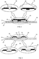
- FIG. 2 shows a three-part piezoelectric treble driver in three different configurations 13, 14 and 15 in cross section.
- the piezoelectric treble driver 13 is on a metallic carrier plate 16 (one-sided or both-sided) a radially polarized piezoceramic substrate 17 applied, which is designed so that it is axially acting electric field with radial contraction or radial Expansion responds.
- the carrier plate 16 is from a centrally located coupling plate 19 and concentric carried by a coupling ring 18.
- Coupling disc 19 and coupling ring 18 are with the carrier plate 16 and with one Sandwich plate 20 glued, which in turn from a rear Cover sheet 21, a front cover sheet 22 and one Sandwich core 23 is made.
- the treble driver 14 according to FIG. 2 emerges from the treble driver 13 in that a centrally arranged support foot 24 is provided, which is used via the treble driver 14 to hold the entire treble speaker.
- a one piece piezoelectric treble driver is shown in Figure 2 in three embodiments 26, 27 and 28 shown in cross section. From an originally flat metallic carrier plate becomes an outer coupling ring due to the tensionless design 30 put up and a central coupling knobs 31 formed. On this embossed carrier plate 29 is a radial Polarized piezoceramic substrate 32 with a central one Recess 33 applied. Coupling ring 30 and coupling knobs 31 of the carrier plate 29 are with the sandwich plate 20th glued.
- the treble driver 27 differs from the treble driver 26 by an additional support ring 35, the also serves the whole over the treble driver 27 Hold treble speakers.
- the treble driver 28 contains accordingly, as an alternative to the support ring 35, a support foot 34.
- FIG. 4 shows two treble loudspeakers 37 according to the invention and 38, which on a membrane 36 of a (much larger) Medium / low-frequency record speakers are attached.
- the piezoelectric treble speaker 37 is by a Membrane 39 and a piezoelectric driver 40 are formed. With the help of the support ring 51, it is able to control the static Load the driver 40 load.
- a electrodynamic treble speaker 38 consisting of a Membrane 39 and an electrodynamic driver 41 by one Support ring 52 is able to support the static load of the driver 41 record.
- FIG. 5 Another alternative is shown in Figure 5, in which two treble speakers according to the invention 42 and 43 each in the Membrane 36 of the mid / low-range plate speaker inserted are.
- the piezoelectric treble speaker 42 with Diaphragm 44 and piezoelectric driver 47 is graded into one Recess 45 recessed in the mid / low-frequency diaphragm 36.
- the dimensionally stable knob profile shown in FIG. 6 is as Sandwich core of a treble multi-resonance plate loudspeaker usable.
- the matrix-like arrangement consists of alternating Rows of aligned nubs 50 such as lines 47 with knobs 50 protruding towards the front (+) alternating with lines 48 that protrude from the back (-) Knobs 49 exist.
- the lines 47 and 48 against each other by half Knub offset Without this offset, the sandwich core would be in one direction of curvature very soft. Because of the offset however, higher rigidity against shear in two axes reached parallel to the knob edges.
- FIG. 5 shows a fractal pattern 59 from (for example) rectangular structural changes in one Sandwich panel 60 in plan view of the membrane surface.
- the whole rectangular area contains a fractal pattern 51 in the form of, for example, rectangular structural changes.
- the entire rectangular area contains as Shape of the structurally modified zone also a rectangle 53, that as a central rectangle from a uniform 3x3 division the original form emerges.
- the (imagined) The remaining eight rectangles of the same size each contain again a centrally positioned rectangular structural change 54, which in turn arose from a 3x3 division. In a further corresponding step, then in similarly smaller rectangles 55.
- Adapted to the size of the structurally modified zones 53, 54 and 55 can be, for example, large 56, medium-sized 57 or small drivers 58 can be used.
Landscapes
- Engineering & Computer Science (AREA)
- Multimedia (AREA)
- Physics & Mathematics (AREA)
- Acoustics & Sound (AREA)
- Signal Processing (AREA)
- Diaphragms For Electromechanical Transducers (AREA)
- Audible-Bandwidth Dynamoelectric Transducers Other Than Pickups (AREA)
- Piezo-Electric Transducers For Audible Bands (AREA)
Abstract
Description
- Figur 1
- einen elektrodynamischen Treiber für einen erfindungsgemäßen Hochtonlautsprecher,
- Figur 2
- eine erste Ausführungsform eines piezoelektrischen Treibers für einen erfindungsgemäßen Hochtonlautsprecher,
- Figur 3
- eine zweite Ausführungsform eines piezoelektrischen Treibers für einen erfindungsgemäßen Hochtonlautsprecher,
- Figur 4
- eine erste Ausführungsform einer Halterung für einen erfindungsgemäßen Hochtonlautsprecher,
- Figur 5
- eine zweite Ausführungsform einer Halterung für einen erfindungsgemäßen Hochtonlautsprecher,
- Figur 6
- eine Ausführungsform eines formstabilen Noppenprofils und
- Figur 7
- eine Ausführungsform eines fraktalen Musters.
- 1
- Diskanttreiber
- 2
- Schwingspalt
- 3
- Sandwichplatte
- 4
- Permanentmagnet
- 5
- Koppelscheibe
- 6
- Schwingspule
- 7
- Spulenträger
- 8
- Spulenwicklung
- 9
- Deckblatt
- 10
- Deckblatt
- 11
- Sandwichkern
- 12
- Stützring
- 13
- Diskanttreiber
- 14
- Diskanttreiber
- 15
- Diskanttreiber
- 16
- Trägerplättchen
- 17
- piezokeramisches Substrat
- 18
- Koppelring
- 19
- Koppelscheibe
- 20
- Sandwichplatte
- 21
- hinteres Deckblatt
- 22
- vorderes Deckblatt
- 23
- Sandwichkern
- 24
- Stützfuß
- 25
- Stützring
- 26
- Diskanttreiber
- 27
- Diskanttreiber
- 28
- Diskanttreiber
- 29
- tiefgezogene Trägerscheibe
- 30
- Koppelring
- 31
- Koppelnoppen
- 32
- piezokeramisches Substrat
- 33
- Aussparung
- 34
- Stützfuß
- 35
- Stützring
- 36
- Mittel-/Tiefton-Plattenlautsprecher
- 37
- Diskantlautsprecher
- 38
- Diskantlautsprecher
- 39
- Sandwichplatte
- 40
- Diskanttreiber
- 41
- Diskanttreiber
- 42
- Diskant-Plattenlautsprecher
- 43
- Diskant-Plattenlautsprecher
- 44
- Sandwichplatte
- 45
- Aussparung
- 46
- Treiber
- 47
- Zeilen
- 48
- Zeilen
- 49
- Noppen
- 50
- Noppen
- 51
- Stützring
- 52
- Stützring
- 53
- strukturveränderte Zone (groß)
- 54
- strukturveränderte Zone (mittel)
- 55
- strukturveränderte Zone (klein)
- 56
- Treiber (groß)
- 57
- Treiber (mittelgroß)
- 58
- Treiber (klein)
- 59
- Fraktales Muster
- 60
- Membran eines Multiresonanzplattenlautsprechers
Claims (14)
- Hochtonlautsprecher mit
einer leichten, freitragenden dünnen Sandwichplatte (3, 20, 39, 60), die zu vielfach reflektierten Biegewellen anregbar ist, und
mindestens einem mit der Sandwichplatte (3, 20, 39, 60) in Schwingungsverbindung stehenden Treiber (1, 13, 14, 15, 26, 27, 28, 40, 41) zum Anregen der Sandwichplatte (3, 20, 39, 60) ,
dadurch gekennzeichnet, dass
der Treiber (1, 13, 14, 15, 26, 27, 28, 40, 41) zur Anregung bei höheren Schallfrequenzen ausgebildet ist,
die Sandwichplatte (3, 20, 39, 60) zur dämpfungsarmen Ausbreitung von Biegewellen ausgebildet ist,
die Sandwichplatte (3, 20, 39, 60) freitragend und dämpfungsarm mittels Halterungselementen (12, 24, 25, 34, 35) gehaltert ist und
die Halterungselemente (12, 24, 25, 34, 35) dämpfungsarm bei höheren Schallfrequenzen ausgebildet sind. - Hochtonlautsprecher nach Anspruch 1, dadurch gekennzeichnet, dass die Sandwichplatte (3) zwei dünne, harte Deckblätter (9, 10) und eine dazwischen liegende, scherfeste, dünne Kernschicht (11) aufweist.
- Hochtonlautsprecher nach Anspruch 2, dadurch gekennzeichnet, dass die Kernschicht (11) eine Wabenstruktur aufweist.
- Hochtonlautsprecher nach Anspruch 2 oder 3, dadurch gekennzeichnet, dass die Kernschicht (11) eine räumlich unterschiedliche Verteilung der elastomechanischen Eigenschaften aufweist.
- Hochtonlautsprecher nach Anspruch 4, dadurch gekennzeichnet, dass in der Kernschicht und/oder den Deckschichten zonenweise Verdünnungen und/oder Aussparungen (53 bis 55) vorgesehen sind.
- Hochtonlautsprecher nach Anspruch 5, dadurch gekennzeichnet, dass die Zonen (53 bis 55) so dimensioniert und angeordnet sind, dass ein Grundmuster sich jeweils in verkleinertem Maßstab wiederholt und sich abermals in diesen kleineren Strukturen wiederholt.
- Hochtonlautsprecher nach einem der Ansprüche 3 bis 6, dadurch gekennzeichnet, dass die Kernschicht (29) eine Folie umfasst, die durch Prägetechnik aufgebrachte periodisch sich wiederholende Ausbuchtungen (31) aufweist.
- Hochtonlautsprecher nach Anspruch 7, dadurch gekennzeichnet, dass Gestalt, Anordnung und Ausrichtung der Ausbuchtungen derart ist, dass die maximale Schubsteifigkeit in alle Momentrichtungen erreicht wird.
- Hochtonlautsprecher nach Anspruch 7 oder 8, dadurch gekennzeichnet, dass
als Ausbuchtungen Noppen (49, 50) in Form einer vierseitigen Pyramide mit quadratischem Grundriss vorgesehen sind und
die Noppen (49, 50) streng periodisch, dicht an dicht und gleichsinnig ausgerichtet in geradlinigen Zeilen (47, 48) angeordnet sind, wobei alternierend jede zweite Zeile (48) durchweg aus Noppen entgegengesetzter Ausrichtung besteht und
jede Zeile (47) gegenüber den benachbarten Zeilen (48) um eine halbe Noppe (49, 50) versetzt ist. - Hochtonlautsprecher nach einem der vorherigen Ansprüche, dadurch gekennzeichnet, dass die Halterungselemente (12, 24, 25, 34, 35) zum Aufsetzen oder Einlassen in eine größere Stützstruktur (36) geeignet sind.
- Hochtonlautsprecher nach Anspruch 10, dadurch gekennzeichnet, dass die Halterungselemente einerseits durch sprödharte Klebung an der Sandwichplatte befestigt und andererseits mit der Stützstruktur verbunden sind.
- Hochtonlautsprecher nach Anspruch 10 oder 11, dadurch gekennzeichnet, dass die Halterungselemente eine Berandung aufweisen und dass die Berandung in einer Aussparung der Stützstruktur spröd-hart verklebt ist.
- Hochtonlautsprecher nach Anspruch 10, 11 oder 12, dadurch gekennzeichnet, dass der Treiber (40, 41, 46, 47) an der Rückseite als Halterelement ausgebildet ist.
- Hochtonlautsprecher nach einem der Ansprüche 10 bis 13, dadurch gekennzeichnet, dass als Stützstruktur (36) die Plattenmembran eines Tief- und/oder Mitteltonplattenlautsprechers vorgesehen ist.
Applications Claiming Priority (2)
| Application Number | Priority Date | Filing Date | Title |
|---|---|---|---|
| DE10025460 | 2000-05-23 | ||
| DE10025460A DE10025460B4 (de) | 2000-05-23 | 2000-05-23 | Hochtonlautsprecher |
Publications (3)
| Publication Number | Publication Date |
|---|---|
| EP1158834A2 true EP1158834A2 (de) | 2001-11-28 |
| EP1158834A3 EP1158834A3 (de) | 2007-05-02 |
| EP1158834B1 EP1158834B1 (de) | 2011-01-19 |
Family
ID=7643216
Family Applications (1)
| Application Number | Title | Priority Date | Filing Date |
|---|---|---|---|
| EP01107224A Expired - Lifetime EP1158834B1 (de) | 2000-05-23 | 2001-03-17 | Hochtonlautsprecher |
Country Status (3)
| Country | Link |
|---|---|
| US (1) | US6888946B2 (de) |
| EP (1) | EP1158834B1 (de) |
| DE (2) | DE10025460B4 (de) |
Cited By (1)
| Publication number | Priority date | Publication date | Assignee | Title |
|---|---|---|---|---|
| CN1926914B (zh) * | 2004-04-07 | 2011-11-30 | 索尼爱立信移动通讯股份有限公司 | 包括流变材料的换能器组件和扬声器 |
Families Citing this family (13)
| Publication number | Priority date | Publication date | Assignee | Title |
|---|---|---|---|---|
| DE19821855A1 (de) | 1998-05-15 | 1999-11-18 | Nokia Deutschland Gmbh | Plattenlautsprecher |
| DE19821862A1 (de) | 1998-05-15 | 1999-11-18 | Nokia Deutschland Gmbh | Schallwiedergabeanordnung |
| DE19825866A1 (de) | 1998-06-10 | 1999-12-16 | Nokia Deutschland Gmbh | Plattenlautsprecher |
| DE19843079A1 (de) | 1998-09-19 | 2000-03-23 | Nokia Deutschland Gmbh | Multiresonanzplatte |
| DE10001410C2 (de) * | 2000-01-14 | 2001-12-06 | Harman Audio Electronic Sys | Flachlautsprecheranordnung |
| US7548854B2 (en) | 2002-01-31 | 2009-06-16 | Awi Licensing Company | Architectural sound enhancement with pre-filtered masking sound |
| US20030142814A1 (en) * | 2002-01-31 | 2003-07-31 | Roy Kenneth P. | Architectural sound enhancement with DTMF control |
| US20030142833A1 (en) * | 2002-01-31 | 2003-07-31 | Roy Kenneth P. | Architectural sound enhancement with test tone diagnostics |
| US6983819B2 (en) * | 2002-04-02 | 2006-01-10 | Awi Licensing Company | Entertainment sound panels |
| US20030198339A1 (en) * | 2002-04-19 | 2003-10-23 | Roy Kenneth P. | Enhanced sound processing system for use with sound radiators |
| GB0211508D0 (en) * | 2002-05-20 | 2002-06-26 | New Transducers Ltd | Transducer |
| DE102012025313B3 (de) * | 2012-12-22 | 2014-02-20 | Audi Ag | Schallwandler zur Wandlung elektrischer Signale in Luftschall |
| US10631072B2 (en) | 2018-06-25 | 2020-04-21 | Google Llc | Actuator for distributed mode loudspeaker with extended damper and systems including the same |
Family Cites Families (13)
| Publication number | Priority date | Publication date | Assignee | Title |
|---|---|---|---|---|
| FR561357A (fr) * | 1922-01-26 | 1923-10-20 | Signal Ges M B H Soc | Membrane pour appareils acoustiques |
| DE1132593B (de) * | 1965-04-05 | 1962-07-05 | Bolt Beranek & Newman | Akustisch wirksame Platte, insbesondere zur Ankopplung an einen elektroakustischen Wandler |
| JPS55161496A (en) * | 1979-05-31 | 1980-12-16 | Matsushita Electric Ind Co Ltd | Diaphragm for speaker and its production |
| GB2246684A (en) * | 1990-08-04 | 1992-02-05 | Secr Defence | Panel form loudspeaker |
| US5425107A (en) * | 1992-04-09 | 1995-06-13 | Bertagni Electronic Sound Transducers, International Corporation | Planar-type loudspeaker with dual density diaphragm |
| UA51671C2 (uk) * | 1995-09-02 | 2002-12-16 | Нью Транзд'Юсез Лімітед | Акустичний пристрій |
| US6188775B1 (en) * | 1995-09-02 | 2001-02-13 | New Transducers Limited | Panel-form loudspeakers |
| US6151402A (en) * | 1995-09-02 | 2000-11-21 | New Transducers Limited | Vibration transducers |
| US6519349B1 (en) * | 1995-09-02 | 2003-02-11 | New Transducers Limited | Loudspeaker |
| GB9818959D0 (en) * | 1998-09-02 | 1998-10-21 | New Transducers Ltd | Panelform loudspeaker |
| US6282298B1 (en) * | 1996-09-03 | 2001-08-28 | New Transducers Limited | Acoustic device |
| DE19757097B4 (de) * | 1997-12-20 | 2004-04-15 | Harman Audio Electronic Systems Gmbh | Schallwiedergabeanordnung |
| US6327329B1 (en) * | 1998-08-25 | 2001-12-04 | General Electric Company | Methods and apparatus for monitoring detector image quality |
-
2000
- 2000-05-23 DE DE10025460A patent/DE10025460B4/de not_active Expired - Fee Related
-
2001
- 2001-03-17 DE DE50115777T patent/DE50115777D1/de not_active Expired - Lifetime
- 2001-03-17 EP EP01107224A patent/EP1158834B1/de not_active Expired - Lifetime
- 2001-04-20 US US09/838,886 patent/US6888946B2/en not_active Expired - Fee Related
Cited By (1)
| Publication number | Priority date | Publication date | Assignee | Title |
|---|---|---|---|---|
| CN1926914B (zh) * | 2004-04-07 | 2011-11-30 | 索尼爱立信移动通讯股份有限公司 | 包括流变材料的换能器组件和扬声器 |
Also Published As
| Publication number | Publication date |
|---|---|
| DE50115777D1 (de) | 2011-03-03 |
| US20010055403A1 (en) | 2001-12-27 |
| EP1158834B1 (de) | 2011-01-19 |
| US6888946B2 (en) | 2005-05-03 |
| DE10025460B4 (de) | 2004-03-18 |
| DE10025460A1 (de) | 2001-12-06 |
| EP1158834A3 (de) | 2007-05-02 |
Similar Documents
| Publication | Publication Date | Title |
|---|---|---|
| DE69605123T3 (de) | Akustisches gerät | |
| DE69602203T2 (de) | Paneelförmige lautsprecher | |
| DE69602102T2 (de) | Inertial schwingungswandler | |
| DE10025460B4 (de) | Hochtonlautsprecher | |
| DE69602101T2 (de) | Inertial-schwingungswandler | |
| DE69601648T2 (de) | Anschlagtafeln mit lautsprechern | |
| EP1120994B1 (de) | Flachlautsprecheranordnung | |
| DE69601725T2 (de) | Lautsprecher mit paneelförmigen akustischen abstrahlelementen | |
| DE68920031T2 (de) | Audiotransducer mit regelbarem flexibilitätsdiaphragma. | |
| DE69601723T2 (de) | Lautsprecher mit plattenförmigen abstrahlelementen | |
| DE69601733T2 (de) | Tragbarer cd-spieler mit lautsprechern mit paneelförmigen akustischen abstrahlelementen | |
| DE60100886T2 (de) | Wandler, insbesondere zum einsatz in akustischen vorrichtungen | |
| DE69602281T2 (de) | Musikinstrumente mit lautsprechern | |
| DE69601724T2 (de) | Grusskarte oder dergleichen mit lautsprecher | |
| DE69601728T2 (de) | Bildschirm mit lautsprechern | |
| DE69602279T2 (de) | Lautsprecher mit paneelförmigen akustischen abstrahlelementen | |
| DE69601732T2 (de) | Verpackung | |
| DE3407980A1 (de) | Kristallschallerzeuger | |
| DE3020659C2 (de) | Schallmembran sowie Verfahren zu ihrer Herstellung | |
| WO1999060820A1 (de) | Treiber für flaches klangpaneel | |
| DE102009040982A1 (de) | Akustischer Wandler und Verfahren zum Erzeugen und/oder Empfangen von Schallwellen, bewegbares Element für einen akustischen Wandler sowie Anordnung zum Bewegen eines bewegbaren Elementes eines akustischen Wandlers | |
| DE69601647T2 (de) | Paneelförmige lautsprecher | |
| EP1078552B1 (de) | Vorrichtung zur dynamischen anregung von plattenlautsprechern | |
| WO1999060819A1 (de) | Schallwiedergabeanordnung nach dem biegewellenprinzip | |
| EP1078551B1 (de) | Plattenlautsprecher |
Legal Events
| Date | Code | Title | Description |
|---|---|---|---|
| PUAI | Public reference made under article 153(3) epc to a published international application that has entered the european phase |
Free format text: ORIGINAL CODE: 0009012 |
|
| AK | Designated contracting states |
Kind code of ref document: A2 Designated state(s): AT BE CH CY DE DK ES FI FR GB GR IE IT LI LU MC NL PT SE TR |
|
| AX | Request for extension of the european patent |
Free format text: AL;LT;LV;MK;RO;SI |
|
| RAP1 | Party data changed (applicant data changed or rights of an application transferred) |
Owner name: HARMAN BECKER AUTOMOTIVE SYSTEMS GMBH |
|
| PUAL | Search report despatched |
Free format text: ORIGINAL CODE: 0009013 |
|
| AK | Designated contracting states |
Kind code of ref document: A3 Designated state(s): AT BE CH CY DE DK ES FI FR GB GR IE IT LI LU MC NL PT SE TR |
|
| AX | Request for extension of the european patent |
Extension state: AL LT LV MK RO SI |
|
| 17P | Request for examination filed |
Effective date: 20070911 |
|
| AKX | Designation fees paid |
Designated state(s): DE FR GB IT |
|
| 17Q | First examination report despatched |
Effective date: 20080314 |
|
| GRAP | Despatch of communication of intention to grant a patent |
Free format text: ORIGINAL CODE: EPIDOSNIGR1 |
|
| RIN1 | Information on inventor provided before grant (corrected) |
Inventor name: ZIGANKI, ANDREAS Inventor name: KRUMP, GERHARD, DR. Inventor name: REGL, HANS-JUERGEN Inventor name: BACHMANN, WOLFGANG, DR. |
|
| GRAS | Grant fee paid |
Free format text: ORIGINAL CODE: EPIDOSNIGR3 |
|
| GRAA | (expected) grant |
Free format text: ORIGINAL CODE: 0009210 |
|
| AK | Designated contracting states |
Kind code of ref document: B1 Designated state(s): DE FR GB IT |
|
| REG | Reference to a national code |
Ref country code: GB Ref legal event code: FG4D Free format text: NOT ENGLISH |
|
| REF | Corresponds to: |
Ref document number: 50115777 Country of ref document: DE Date of ref document: 20110303 Kind code of ref document: P |
|
| REG | Reference to a national code |
Ref country code: DE Ref legal event code: R096 Ref document number: 50115777 Country of ref document: DE Effective date: 20110303 |
|
| PLBE | No opposition filed within time limit |
Free format text: ORIGINAL CODE: 0009261 |
|
| STAA | Information on the status of an ep patent application or granted ep patent |
Free format text: STATUS: NO OPPOSITION FILED WITHIN TIME LIMIT |
|
| 26N | No opposition filed |
Effective date: 20111020 |
|
| PG25 | Lapsed in a contracting state [announced via postgrant information from national office to epo] |
Ref country code: IT Free format text: LAPSE BECAUSE OF FAILURE TO SUBMIT A TRANSLATION OF THE DESCRIPTION OR TO PAY THE FEE WITHIN THE PRESCRIBED TIME-LIMIT Effective date: 20110119 |
|
| REG | Reference to a national code |
Ref country code: DE Ref legal event code: R097 Ref document number: 50115777 Country of ref document: DE Effective date: 20111020 |
|
| REG | Reference to a national code |
Ref country code: FR Ref legal event code: PLFP Year of fee payment: 15 |
|
| PGFP | Annual fee paid to national office [announced via postgrant information from national office to epo] |
Ref country code: DE Payment date: 20150327 Year of fee payment: 15 |
|
| PGFP | Annual fee paid to national office [announced via postgrant information from national office to epo] |
Ref country code: FR Payment date: 20150317 Year of fee payment: 15 Ref country code: GB Payment date: 20150327 Year of fee payment: 15 |
|
| REG | Reference to a national code |
Ref country code: DE Ref legal event code: R119 Ref document number: 50115777 Country of ref document: DE |
|
| GBPC | Gb: european patent ceased through non-payment of renewal fee |
Effective date: 20160317 |
|
| REG | Reference to a national code |
Ref country code: FR Ref legal event code: ST Effective date: 20161130 |
|
| PG25 | Lapsed in a contracting state [announced via postgrant information from national office to epo] |
Ref country code: FR Free format text: LAPSE BECAUSE OF NON-PAYMENT OF DUE FEES Effective date: 20160331 Ref country code: GB Free format text: LAPSE BECAUSE OF NON-PAYMENT OF DUE FEES Effective date: 20160317 Ref country code: DE Free format text: LAPSE BECAUSE OF NON-PAYMENT OF DUE FEES Effective date: 20161001 |