EP1157905A2 - Automotive seatbelt take-up device - Google Patents
Automotive seatbelt take-up device Download PDFInfo
- Publication number
- EP1157905A2 EP1157905A2 EP01103929A EP01103929A EP1157905A2 EP 1157905 A2 EP1157905 A2 EP 1157905A2 EP 01103929 A EP01103929 A EP 01103929A EP 01103929 A EP01103929 A EP 01103929A EP 1157905 A2 EP1157905 A2 EP 1157905A2
- Authority
- EP
- European Patent Office
- Prior art keywords
- take
- seatbelt
- spring
- shaft
- force
- Prior art date
- Legal status (The legal status is an assumption and is not a legal conclusion. Google has not performed a legal analysis and makes no representation as to the accuracy of the status listed.)
- Granted
Links
Images



Classifications
-
- B—PERFORMING OPERATIONS; TRANSPORTING
- B60—VEHICLES IN GENERAL
- B60R—VEHICLES, VEHICLE FITTINGS, OR VEHICLE PARTS, NOT OTHERWISE PROVIDED FOR
- B60R22/00—Safety belts or body harnesses in vehicles
- B60R22/34—Belt retractors, e.g. reels
-
- B—PERFORMING OPERATIONS; TRANSPORTING
- B60—VEHICLES IN GENERAL
- B60R—VEHICLES, VEHICLE FITTINGS, OR VEHICLE PARTS, NOT OTHERWISE PROVIDED FOR
- B60R22/00—Safety belts or body harnesses in vehicles
- B60R22/34—Belt retractors, e.g. reels
- B60R22/44—Belt retractors, e.g. reels with means for reducing belt tension during use under normal conditions
-
- B—PERFORMING OPERATIONS; TRANSPORTING
- B60—VEHICLES IN GENERAL
- B60R—VEHICLES, VEHICLE FITTINGS, OR VEHICLE PARTS, NOT OTHERWISE PROVIDED FOR
- B60R22/00—Safety belts or body harnesses in vehicles
- B60R22/34—Belt retractors, e.g. reels
- B60R22/44—Belt retractors, e.g. reels with means for reducing belt tension during use under normal conditions
- B60R2022/442—Belt retractors, e.g. reels with means for reducing belt tension during use under normal conditions using one spring and one additional retraction device in parallel
- B60R2022/4426—Belt retractors, e.g. reels with means for reducing belt tension during use under normal conditions using one spring and one additional retraction device in parallel the additional retraction device being a second spring
- B60R2022/4433—Belt retractors, e.g. reels with means for reducing belt tension during use under normal conditions using one spring and one additional retraction device in parallel the additional retraction device being a second spring externally controlled
Definitions
- the present invention relates to an automotive seatbelt take-up device. More specifically, the present invention relates to a device that significantly reduces pressure applied by the seatbelt on the passenger when the seatbelt is worn.
- a seatbelt take-up device includes a spiral spring used to take-up the seatbelt.
- the seatbelt is drawn out in opposition to the spring force from the spiral spring, and a tongue is inserted into a buckle.
- the spiral spring biases the seatbelt in the take-up direction so that the seatbelt is tightened around the chest of the passenger, and the passenger feels pressure from the seatbelt.
- Japanese patent publication number 60-30576 describes a take-up device implemented to reduce the seatbelt take-up force.
- Two spiral springs, one weak and one strong, having different elastic biasing forces, are connected in series.
- the weak and strong spiral springs are used when the seatbelt is drawn out or taken in.
- the weak spring is used to reduce the take-up force.
- this take-up device uses two spiral springs, resulting in a complex structure having high production costs.
- Japanese laid-open patent publication number 10-78786 proposes a seatbelt take-up device to reduce the take-up force when the seatbelt is worn.
- This conventional seatbelt take-up device has a spring clutch which provides a braking force to the take-up force of the spiral spring.
- This conventional take-up device includes a shaft moving in tandem with a seatbelt take-up shaft; a spiral spring biasing the shaft in the take-up direction; a ratchet wheel restricted by a solenoid actuator to prevent rotation in the seatbelt take-up direction when the seatbelt is worn; and a spring clutch assembled along the shaft and the ratchet wheel.
- the spring clutch provides torque transfer for the clutch spring when the seatbelt is being taken up while being worn.
- the spring clutch provides a braking action via friction sliding ofthe clutch spring when the shaft rotates in the seatbelt take-up direction.
- the friction coefficient of the clutch spring varies greatly due to vibration in the automobile. This variation prevents stable braking action (stable take-up force reduction) and makes it difficult to reliably provide adequate pressure on the seatbelt.
- the present invention provides an automotive seatbelt take-up device has a primary spiral spring biasing a take-up shaft in a seatbelt take-up direction.
- a spring clutch transfers rotation of the take-up shaft in a seatbelt drawing-out direction to a ring.
- a secondary spiral spring is capable of generating rotational biasing forces on the take-up shaft in a direction opposite that of the primary spiral spring.
- an automotive seatbelt take-up device includes a take-up shaft operating in tandem with an automotive seatbelt take-up shaft; a primary spiral spring fixed to the take-up shaft, biasing the take-up shaft in a take-up direction; and a balance spring capable of generating a rotational bias force in a direction opposite that of the primary spiral spring.
- the balance spring may be a secondary spiral spring roughly similar to the primary spiral spring with fewer windings, or, alternatively, the balance spring can be a torsion spring.
- the rotational bias force generated by the balance spring (this is a rotational bias force going in the opposite direction from the primary spiral spring) act upon the take- up shaft when the seatbelt is secured to the passenger. If this is done, when the seatbelt is taken up after it is secured, the balance spring is wound tight so that the take-up force of the take-up shaft is reduced. If the seatbelt is subsequently drawn out, a release elastic force, releasing the balance spring that had been wound tight, assists the take-up shaft in the drawing-out direction.
- an automotive seatbelt take-up device includes a take-up shaft operating in tandem with an automotive seatbelt take-up shaft; a primary spiral spring fixed to the take-up shaft at its inner end portion and biasing the take-up shaft in a take-up direction; a spring clutch including a ring and a clutch spring fitted to the outside of the take-up shaft and transferring rotation in a seatbelt drawing-out direction to the ring; a balance spring capable of generating a rotational bias force in a direction opposite to that of the primary spiral spring, one end of the balance spring being fixed to the ring; and a ratchet wheel capable of using restricting means to restrict rotation in a seatbelt take-up direction, another end ofthe balance spring being fixed to the ratchet wheel.
- the balance spring here can be, for example, a secondary spiral spring similar to the primary spiral spring with fewer windings (e.g., around 3 - 10 windings).
- a torsion spring similar to this secondary spiral spring can be used as the balance spring.
- the restricting means is not activated until the seatbelt is secured to the passenger, and the balance spring is in a free state since the ratchet wheel can rotate freely.
- restricting means restricts rotation of the ratchet wheel so that it cannot rotate in the take-up direction.
- the friction transfer provided by the spring clutch is used to transfer the rotation of the take-up shaft to the ring, rotating the ring so that the balance spring is wound tight. In this manner, the take-up force of the take-up shaft is reliably reduced by the tightly wound state of the balance spring, and the passenger is only weakly constrained by the seatbelt.
- the spring clutch When the seatbelt is worn and the passenger's body is moved to draw out the seatbelt, the spring clutch is in a transferring state so that the release elastic force of the balance spring assists the take-up shaft. Thus, the passenger is only weakly constrained by the seatbelt.
- the friction transfer provided by the spring clutch causes the balance spring to be wound tightly, as described above, and the take-up force of the take-up shaft is reduced by the tightly wound state of the balance spring. This state results in the passenger being only weakly constrained by the seatbelt.
- an automotive seatbelt take-up device as described above wherein, when the seatbelt is being worn by a passenger and the take-up shaft rotates in the take-up direction while the ratchet wheel applies rotation restriction, the spring clutch provides friction transfer to wind the balance spring tight, thus reducing take-up force from the take-up shaft. Generally, slack in the seatbelt is taken up after the seatbelt is secured to the passenger. When the take-up shaft is rotated in the take-up direction while the ratchet wheel is restricted, the friction transfer provided by the spring clutch winds the balance spring tightly and reduces the take-up force of the take-up shaft.
- an automotive seatbelt take-up device as described above wherein, when the seatbelt is being worn and the seatbelt is drawn out while the ratchet wheel applies rotation restriction, a release elastic force of the balance spring assists, by way of the spring clutch, the take-up shaft in the drawing-out direction.
- the seatbelt When the passenger's body moves while the seatbelt is secured, the seatbelt is drawn out. Since the balance spring is wound tight up to this point, as described above, when the seatbelt is drawn out, the release elastic force of the balance spring can, via the spring clutch, assist the take-up shaft in the drawing-out direction. Thus, the passenger experiences only a weak constraining force.
- an automotive seatbelt take-up device as described above wherein, when the seatbelt is taken up after being drawn out, the spring clutch provides friction transfer to wind the balance spring tight, thus reducing take-up force of the take-up shaft.
- the friction transfer of the spring clutch winds the balance spring tightly, thus reducing the take-up force of the take-up shaft.
- an automotive seatbelt take-up device as described above, wherein the balance spring is a spiral spring. Since the balance spring is a spiral spring, the balance spring can be mounted, for example, between the ring and the ratchet wheel. This provides a more compact take-up device.
- an automotive seatbelt take-up device as described above, wherein the balance spring is a torsion spring. Since the balance spring is a torsion spring, the production cost of the balance spring is reduced.
- Fig. 1 is an exploded perspective drawing of a seatbelt device according to an embodiment of the present invention.
- Fig. 2 is a perspective drawing of a take-up device.
- Fig. 3 is a schematic perspective drawing of a take-up device.
- Fig. 4 is an exploded vertical cross-section drawing of the main elements of a take-up device.
- Fig. 5 is a side-view drawing of a take-up device when the rotation of the ratchet wheel is restricted.
- Fig. 6 is a side-view drawing of a take-up device when the rotation of the ratchet wheel is not restricted.
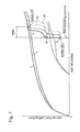
- Fig. 7 is a drawing showing the characteristics of the take-up force/drawing-out force of a take-up device.
- Fig. 8 is a table showing the status of various members in various operations
- a seatbelt device 1 includes a take-up device 2, a housing 3, a reel 5 housed in housing 3 to reel in a seat belt 4, and a seat-belt take-up shaft 6 (hereinafter referred to as take-up shaft 6) secured by being fitted inside reel 5, passing through reel 5 so that take-up shaft 6 is rotatably supported in housing 3.
- take-up device 2 includes a primary spiral spring 10, a disk 11, a ratchet wheel 12, a secondary spiral spring 13 (also known as balance spring 13), a ring 14, a clutch spring 15, a take-up shaft 16, a ratchet claw 17, a torsion spring 18, and a solenoid actuator 19.
- These members 10 - 19 are housed inside a case member 20 secured to the right wall of housing 3.
- Primary spiral spring 10 is housed in a cap 20a at the right of case member 20.
- Disk 11 and ring-shaped ratchet wheel 12 are disposed to the left of primary spiral spring 10.
- Disk 11 is secured to ratchet wheel 12.
- Secondary spiral spring 13 is secured to the inside of ratchet wheel 12.
- Ring 14 is disposed in secondary spiral spring 13.
- Clutch spring 15 is disposed inside ring 14.
- Disk 11 is rotatably housed in case member 20, and ratchet wheel 12 is rotatable around the axis of take-up shaft 6.
- Take-up shaft 16 is integrally formed from a first shaft 16a, a second shaft 16b, to the right thereof (with a smaller diameter than the first shaft 16a), and a flange 16c, near the left end of first shaft 16a.
- a rectangular hole 16d, on first shaft 16a, is fitted with a rectangular connector 6a on the right end of take-up shaft 6, linking take-up shaft 16 and take-up shaft 6.
- First shaft 16a is disposed inside clutch spring 15 and ring 14.
- Second shaft 16b passing through an insertion opening 11a of disk 11, is disposed inside primary spiral spring 10.
- Flange 16c is roughly abutted against the left surface of ring 14.
- a rightwardly projecting shaft (not shown in the figure) is formed on the right end of take-up shaft 16. This shaft is rotatably supported by a cavity (not shown in the figure) at the center of case member 20.
- an arrow a indicates the rotation direction (take-up direction) of take-up shaft 16 (take-up shaft 6) when seat belt 4 is reeled in.
- An arrow b indicates the rotation direction (drawing-out direction) of take-up shaft 16 when seatbelt 4 is drawn out.
- Primary spiral spring 10 is wound outward from a take-up center section 10a in the direction of the take-up direction a.
- Take-up center section 10a is secured to take-up shaft 16 by engaging the inner end of primary spiral spring 10 to a slit 16e formed on first shaft 16b.
- the outer end of primary spiral spring 10 is secured by engaging with an engagement piece 20b formed on the inside of case member 20.
- Seatbelt 4, wrapped almost completely around reel 5, is drawn out so that take-up shaft 16 rotates in the drawing-out direction b. This causes primary spiral spring 10 to be wound tight, and the resulting biasing causes take-up shaft 6 and take-up shaft 16 to be biased in the take-up direction a.
- Secondary spiral spring 13 is wound from the inside outward in the drawing-out direction b, with, e.g., 3 - 10 windings.
- the inner end of secondary spiral spring 13 is secured by engaging with a slit 14a formed in ring 14.
- the outer end of secondary spiral spring 13 is secured by being engaged to a slit 12a formed on ratchet wheel 12.
- Secondary spiral spring 13 can generate rotational biasing force on take-up shaft 16 in the drawing-out direction b (reverse from primary spiral spring 10).
- Clutch spring 15 is a torsion spring formed by tightly winding (e.g., two windings) an elastic wire into a coil shape. Clutch spring 15 is tightly fitted to the outside of first shaft 16a of take-up shaft 16 to provide friction bonding. Clutch spring 15 is wound from one end 15a in the direction of the take-up direction a. The other end 15b is bent upward and engages with an engagement groove 14b formed on the inner perimeter section of ring 14.
- Take-up shaft 16, clutch spring 15 and ring 14 form a spring clutch 25 that transfers the rotation of take-up shaft 16 in the drawing-out direction b to ring 14.
- clutch spring 15 When the take-up shaft 16 rotates in the drawing-out direction b, the friction between the take-up shaft 16 and clutch spring 15 causes clutch spring 15 to be wound tighter, so that clutch 25 is in a locked state.
- Clutch spring 15 and take-up shaft 16 are joined firmly so that torque can be transferred between them, and this allows the rotation of the take-up shaft 16 in the drawing-out direction b to be transferred reliably to the ring 14.
- T1 is the rotational bias force of the primary spiral spring 10
- T2 is the rotational bias force of the secondary spiral spring 13
- T3 is the torque transferred without slippage via the frictional transfer provided by spring clutch 25.
- a rotation restricting mechanism 26 includes ratchet claw 17, torsion spring 18, and solenoid actuator 19.
- Rotation restricting mechanism 26 restricts ratchet wheel 12, preventing it from rotating in the take-up direction a.
- Ratchet claw 17 is integrally formed from a pivot section 17a, an arm 17b, and a lever 17c.
- Pivot section 17a is pivotably supported by a support shaft 20c of case member 20 roughly directly below ratchet wheel 12.
- Arm 17b extends rearward from pivot section 17a and lever 17c extends downward.
- Torsion spring 18 is mounted on a pin 20d of case member 20. Torsion spring 18 biases arm 17b in the direction of engagement with the teeth of ratchet wheel 12. Solenoid actuator 19 is secured to case member 20 to the rear of lever 17c. An output section 19a pushes lever 17c forward so that the engagement between arm 17b and ratchet wheel 12 is released.
- seatbelt device 1 is equipped with a tongue attached to seatbelt 4 and a buckle disposed in a fixed manner to the auto body.
- the passenger wears seatbelt 4 by connecting the tongue and the buckle.
- Solenoid actuator 19 and a detection switch for detecting the joined state of the buckle are electrically connected to a control device (not shown in the figures). This control device controls solenoid actuator 19 based on the whether or not the tongue and the buckle are joined.
- solenoid actuator 19 disengages ratchet claw 17 from ratchet wheel 12 when seatbelt 4 is disengaged (i.e., the tongue and the buckle are not joined), allowing ratchet wheel 12 to rotate freely.
- solenoid actuator 19 is turned on. Ratchet claw 17 engages with ratchet wheel 12 to prevent ratchet wheel 12 from rotating in the take-up direction a.
- secondary spiral spring 13 If secondary spiral spring 13 generates a rotational bias force on take-up shaft 16 in the drawing-out direction b, the rotational bias force will be smaller than the rotational bias force from primary spiral spring 10 in the take-up direction a.
- secondary spiral spring 13 will be wound to a point where a predetermined rotational bias force (a bias slightly smaller than that of primary spiral spring 10). At this point, slippage will take place between clutch spring 15 and take-up shaft 16, thus preventing secondary spiral spring 13 from being wound tighter to produce a greater rotational bias force.
- secondary spiral spring 13 can be set freely based on the size of the biasing force from primary spiral spring 10.
- the biasing force from primary spiral spring 10 can be increased while still allowing secondary spiral spring 13 to provide reduced take-up force and assistance in the drawing out the belt. This improves the take-up performance of seatbelt 4.
- the reduction in take-up force and the assistance in drawing out the belt provided by secondary spiral spring 13 can be set up in a stable manner that is not affected by vibrations and the like, thus providing a highly reliable take-up device.
- rotation of ratchet wheel 12 is restricted, thus eliminating ratchet noise.
- the automotive seatbelt take-up device of the present invention is not restricted to the take-up device of the embodiment described above, and various modifications may be added as long as they do not depart from the spirit of the present invention.
- the balance spring when the seatbelt is secured to the passenger and the seatbelt is then taken up, the balance spring is wound tight so that the take-up force is reduced. Also, when the seatbelt is subsequently drawn out, the balance spring that had been wound tight is released with a release elastic force that assists the take-up shaft in the drawing-out direction.
- the balance spring when the seatbelt is secured to the passenger and the rotation of the ratchet wheel is restricted, the balance spring is wound tightly when the seatbelt is taken up after it is secured. This reduces the take-up force.
- the release elastic force of the balance spring assists the drawing out of the seatbelt, thus allowing the tightly wound state of the balance spring to reduce the take-up force when the seatbelt is subsequently taken up.
- the balance spring characteristics can be set freely based on the degree of biasing force provided by the primary spiral spring.
- the reduction of the take-up force and the assistance in drawing out provided by the balance spring can be maintained while the biasing from the primary spiral spring is increased, and the take-up performance for the seatbelt is improved.
- the take-up force reduction and drawing-out assistance of the balance spring can be set up to have stable characteristics that are not affected by vibrations and the like. This provides a highly reliable take-up device.
- the balance spring when the seatbelt is being worn, the balance spring is tightly wound so that the take-up force for taking up the seatbelt is reduced.
- the release elastic force of the balance spring assists the action in the drawing-out direction. Furthermore, when the balance spring is released, the ratchet wheel does not rotate so there is no ratchet noise.
- the balance spring when the seatbelt is being worn and is taken up after being drawn out, the balance spring is wound tight so that the take-up force for taking up the seatbelt is reduced.
- the balance spring is preferably formed from a spiral spring.
- the balance spring can be interposed between the ring and the ratchet wheel so that the take-up device can be made compact.
- Other advantages are similar as those described above.
- the balance spring is preferably formed from a torsion spring. This allows the production costs of the balance spring to be reduced. Other advantages are similar as those described above.
- An automotive seatbelt take-up device has a primary spiral spring biasing a take-up shaft in a seatbelt take-up direction.
- a spring clutch transfers rotation of the take-up shaft in a seatbelt drawing-out direction to a ring.
- a secondary spiral spring is capable of generating rotational biasing force on the take-up shaft in a direction opposite that of the primary spiral spring.
Landscapes
- Engineering & Computer Science (AREA)
- Mechanical Engineering (AREA)
- Automotive Seat Belt Assembly (AREA)
Abstract
Description
Referring to Fig. 7, the take-up force of take-up
Referring specifically to Fig. 7, the curve (IIa) and the curve (IIb) show slack elimination characteristics once seatbelt 4 is pulled out further and secured. In these cases,
Claims (8)
- An automotive seatbelt take-up device comprising:a take-up shaft;a primary spiral spring biasing said take-up shaft in a take-up direction; anda balance spring capable of generating a rotational bias force in a direction opposite that of said primary spiral spring.
- An automotive seatbelt take-up device comprising:a take-up shaft operatively connected to a seatbelt take-up shaft;a primary spiral spring fixed to said take-up shaft, biasing said take-up shaft in a take-up direction;a spring clutch, including a ring and a clutch spring, fitted to the outside of said take-up shaft, transferring rotation of said take-up shaft in a seatbelt drawing-out direction to said ring;a balance spring capable of generating a rotational bias force in a direction opposite to that of said primary spiral spring, one end of said balance spring being fixed to said ring;a ratchet wheel fixed to another end of said balance spring; andrestricting means capable of restricting said ratchet wheel, thereby preventing rotation in said seatbelt take-up direction.
- An automotive seatbelt take-up device as described in claim 2 wherein, when said seatbelt is being worn by a passenger and said take-up shaft rotates in said seatbelt take-up direction while rotation of said ratchet wheel is restricted, said spring clutch provides friction transfer to wind said balance spring tight, thus reducing a take-up force of said take-up shaft.
- An automotive seatbelt take-up device as described in claim 3 wherein, when said seatbelt is being worn and said seatbelt is drawn out while rotation of said ratchet wheel is restricted, a release elastic force of said balance spring assists, by way of said spring clutch, rotation of said take-up shaft in said drawing-out direction.
- An automotive seatbelt take-up device as described in claim 4 wherein, when said seatbelt is taken up after being drawn out, said spring clutch provides friction transfer to wind said balance spring tight, thus reducing take-up force of said take-up shaft.
- An automotive seatbelt take-up device as described in claim 2 wherein said balance spring is a spiral spring.
- An automotive seatbelt take-up device as described in claim 2 wherein said balance spring is a torsion spring.
- An automotive seatbelt take-up device as described in claim 2 wherein said primary spiral spring is fixed at its inner end portion to said take-up shaft.
Applications Claiming Priority (2)
| Application Number | Priority Date | Filing Date | Title |
|---|---|---|---|
| JP2000074362A JP3396027B2 (en) | 2000-03-16 | 2000-03-16 | Automotive seat belt winding device |
| JP2000074362 | 2000-03-16 |
Publications (3)
| Publication Number | Publication Date |
|---|---|
| EP1157905A2 true EP1157905A2 (en) | 2001-11-28 |
| EP1157905A3 EP1157905A3 (en) | 2002-01-02 |
| EP1157905B1 EP1157905B1 (en) | 2005-02-09 |
Family
ID=18592433
Family Applications (1)
| Application Number | Title | Priority Date | Filing Date |
|---|---|---|---|
| EP01103929A Expired - Lifetime EP1157905B1 (en) | 2000-03-16 | 2001-02-16 | Automotive seatbelt take-up device |
Country Status (6)
| Country | Link |
|---|---|
| US (1) | US6431485B2 (en) |
| EP (1) | EP1157905B1 (en) |
| JP (1) | JP3396027B2 (en) |
| KR (1) | KR100511848B1 (en) |
| CN (1) | CN1172813C (en) |
| DE (1) | DE60108805T2 (en) |
Cited By (3)
| Publication number | Priority date | Publication date | Assignee | Title |
|---|---|---|---|---|
| EP1316483A3 (en) * | 2001-11-30 | 2004-01-07 | DaimlerChrysler AG | Safety belt pretensioner |
| DE102005017367A1 (en) * | 2005-04-14 | 2006-10-19 | Hugo Kern Und Liebers Gmbh & Co. Kg Platinen- Und Federnfabrik | Rolling-up device for safety belt has freewheel coupling to transmit force from shaft to compensation spring with locking wheel locked |
| CN1847062B (en) * | 2005-04-14 | 2011-12-07 | 胡戈克恩和利伯斯两合公司板簧生产厂 | Safety belt automatic flexing device with free wheel clutch |
Families Citing this family (22)
| Publication number | Priority date | Publication date | Assignee | Title |
|---|---|---|---|---|
| JP3575475B2 (en) * | 2002-05-10 | 2004-10-13 | 日産自動車株式会社 | Vehicle seat belt device |
| JP4571427B2 (en) * | 2004-04-01 | 2010-10-27 | 株式会社東海理化電機製作所 | Webbing take-up device |
| JP4580253B2 (en) * | 2005-02-21 | 2010-11-10 | 株式会社東海理化電機製作所 | Webbing take-up device |
| KR100747247B1 (en) * | 2005-10-26 | 2007-08-07 | 현대자동차주식회사 | Seat belt assist device |
| US7862582B2 (en) * | 2006-05-02 | 2011-01-04 | Ethicon Endo-Surgery, Inc. | Suture management |
| DE102006052167B3 (en) * | 2006-11-02 | 2008-02-21 | Hugo Kern Und Liebers Gmbh & Co. Kg Platinen- Und Federnfabrik | Safety belt rolling device comprises blocking element with two opposite ends, where blocking element works together with tooth of blocking ring, and two ends of blocking element comprise mutual angle separation in peripheral direction |
| JP5376120B2 (en) * | 2008-12-12 | 2013-12-25 | オートリブ ディベロップメント エービー | Seat belt retractor |
| JP5243386B2 (en) * | 2009-10-20 | 2013-07-24 | 株式会社東海理化電機製作所 | Webbing take-up device |
| JP5399283B2 (en) * | 2010-02-03 | 2014-01-29 | 株式会社東海理化電機製作所 | Webbing take-up device |
| JP2011157042A (en) * | 2010-02-03 | 2011-08-18 | Tokai Rika Co Ltd | Webbing take-up device |
| JP5314611B2 (en) | 2010-02-03 | 2013-10-16 | 株式会社東海理化電機製作所 | Webbing take-up device |
| JP5456619B2 (en) * | 2010-08-27 | 2014-04-02 | 株式会社東海理化電機製作所 | Webbing take-up device |
| DE102010051418A1 (en) * | 2010-11-17 | 2012-05-24 | Trw Automotive Gmbh | Belt retractor for a safety belt system and method for assembling a belt retractor |
| JP5657370B2 (en) * | 2010-12-15 | 2015-01-21 | タカタ株式会社 | Seat belt retractor and seat belt device provided with the same |
| CN103029678B (en) * | 2011-10-07 | 2015-06-10 | 株式会社东海理化电机制作所 | Webbing retractor |
| JP5784563B2 (en) * | 2012-09-24 | 2015-09-24 | 株式会社東海理化電機製作所 | Webbing take-up device |
| DE102013201849B4 (en) * | 2013-02-05 | 2015-08-27 | Autoliv Development Ab | Seat belt retractor with a 2-spring comfort function |
| CN105459948B (en) * | 2014-08-08 | 2018-03-27 | 比亚迪股份有限公司 | Vehicle and its Webbing take-up device |
| US9372382B2 (en) * | 2014-11-14 | 2016-06-21 | Htc Corporation | Rotary mechanism |
| DE102018128033A1 (en) * | 2018-11-09 | 2020-05-14 | Trw Automotive Gmbh | Belt shaft housing, belt shaft, belt tensioner and method for assembling a belt tensioner |
| CN111845621B (en) * | 2020-07-20 | 2022-01-07 | 重庆广播电视大学重庆工商职业学院 | Safety belt capable of reducing oppressive feeling of fastening |
| CN115991167B (en) * | 2023-02-02 | 2025-09-02 | 奇瑞汽车股份有限公司 | Comfort seat belt retractor |
Family Cites Families (11)
| Publication number | Priority date | Publication date | Assignee | Title |
|---|---|---|---|---|
| US4026494A (en) * | 1976-04-26 | 1977-05-31 | American Safety Equipment Corporation | Safety belt tension reducing means |
| US4303208A (en) * | 1976-04-26 | 1981-12-01 | American Safety Equipment Corp. | Friction clutch operated reduced tension safety retraction means |
| US4108393A (en) * | 1976-08-16 | 1978-08-22 | American Safety Equipment Corporation | Emergency locking retractor with comfort belt tension |
| JPS6030576B2 (en) * | 1979-08-21 | 1985-07-17 | エヌエスケ−・ワ−ナ−株式会社 | Seatbelt retractor winding force reduction mechanism |
| US4361294A (en) | 1980-11-21 | 1982-11-30 | Gateway Industries, Inc. | Tension relieving mechanism |
| US5131594A (en) * | 1990-07-24 | 1992-07-21 | Trw Vehicle Safety Systems Inc. | Seat belt comfort mechanism |
| US5265823A (en) | 1991-06-03 | 1993-11-30 | Takata Inc. | Tension relieving mechanism for a safety belt system |
| DE59105469D1 (en) * | 1991-11-21 | 1995-06-14 | Trw Repa Gmbh | Belt retractor with strain relief for seat belt restraint systems in vehicles. |
| US5411221A (en) * | 1993-05-24 | 1995-05-02 | Allied-Signal Inc. | Seat belt retractor with tension relief mechanism |
| JPH082380A (en) * | 1994-04-21 | 1996-01-09 | Nippon Seiko Kk | Seat belt retractor |
| US5457762A (en) | 1994-06-13 | 1995-10-10 | Siecor Corporation | Fiber optic ribbon |
-
2000
- 2000-03-16 JP JP2000074362A patent/JP3396027B2/en not_active Expired - Fee Related
- 2000-12-26 CN CNB001377973A patent/CN1172813C/en not_active Expired - Lifetime
-
2001
- 2001-01-29 US US09/772,248 patent/US6431485B2/en not_active Expired - Lifetime
- 2001-02-16 DE DE60108805T patent/DE60108805T2/en not_active Expired - Lifetime
- 2001-02-16 EP EP01103929A patent/EP1157905B1/en not_active Expired - Lifetime
- 2001-03-06 KR KR10-2001-0011466A patent/KR100511848B1/en not_active Expired - Lifetime
Cited By (6)
| Publication number | Priority date | Publication date | Assignee | Title |
|---|---|---|---|---|
| EP1316483A3 (en) * | 2001-11-30 | 2004-01-07 | DaimlerChrysler AG | Safety belt pretensioner |
| US6851716B2 (en) | 2001-11-30 | 2005-02-08 | Daimlerchrysler Ag | Belt tightener |
| DE102005017367A1 (en) * | 2005-04-14 | 2006-10-19 | Hugo Kern Und Liebers Gmbh & Co. Kg Platinen- Und Federnfabrik | Rolling-up device for safety belt has freewheel coupling to transmit force from shaft to compensation spring with locking wheel locked |
| DE102005017367B4 (en) * | 2005-04-14 | 2007-07-19 | Hugo Kern Und Liebers Gmbh & Co. Kg Platinen- Und Federnfabrik | Belt retractor with overrunning clutch |
| CN1847062B (en) * | 2005-04-14 | 2011-12-07 | 胡戈克恩和利伯斯两合公司板簧生产厂 | Safety belt automatic flexing device with free wheel clutch |
| CN1847063B (en) * | 2005-04-14 | 2011-12-14 | 胡戈克恩和利伯斯两合公司板簧生产厂 | Safety belt automatic flexing device with free wheel clutch |
Also Published As
| Publication number | Publication date |
|---|---|
| DE60108805D1 (en) | 2005-03-17 |
| EP1157905B1 (en) | 2005-02-09 |
| JP3396027B2 (en) | 2003-04-14 |
| KR100511848B1 (en) | 2005-09-02 |
| CN1314271A (en) | 2001-09-26 |
| US20010022330A1 (en) | 2001-09-20 |
| US6431485B2 (en) | 2002-08-13 |
| KR20010091927A (en) | 2001-10-23 |
| DE60108805T2 (en) | 2006-05-18 |
| JP2001260814A (en) | 2001-09-26 |
| CN1172813C (en) | 2004-10-27 |
| EP1157905A3 (en) | 2002-01-02 |
Similar Documents
| Publication | Publication Date | Title |
|---|---|---|
| EP1157905B1 (en) | Automotive seatbelt take-up device | |
| US4199172A (en) | Seat belt retractor with tension eliminating mechanism | |
| JP2005289259A (en) | Webbing winding device | |
| JP2014141137A (en) | Webbing take-up apparatus | |
| JP5921405B2 (en) | Webbing take-up device | |
| JP2001233175A (en) | Webbing winding device | |
| JP5112964B2 (en) | Webbing take-up device | |
| JP5714624B2 (en) | Webbing take-up device | |
| US7240923B2 (en) | Seatbelt retractor and seatbelt device | |
| JP2006199116A (en) | Webbing take-up device | |
| JP4845805B2 (en) | Vehicle seat belt device | |
| JP4571428B2 (en) | Webbing take-up device | |
| JP4101481B2 (en) | Winding device for automobile seat belt | |
| JP2009078633A (en) | Seat belt retractor | |
| JP4021166B2 (en) | Automotive seat belt retractor | |
| JP5137005B2 (en) | Seat belt retractor | |
| CN100469623C (en) | electric retractor | |
| JP5456619B2 (en) | Webbing take-up device | |
| JPH07309203A (en) | Storage retractor of seatbelt web | |
| JP4498075B2 (en) | Motor retractor | |
| JP2004042789A (en) | Webbing take-up device | |
| JP3524726B2 (en) | Automotive seat belt winding device | |
| JP5657370B2 (en) | Seat belt retractor and seat belt device provided with the same | |
| JP4291747B2 (en) | Motor retractor | |
| JP2005329797A (en) | Webbing take-up device |
Legal Events
| Date | Code | Title | Description |
|---|---|---|---|
| PUAI | Public reference made under article 153(3) epc to a published international application that has entered the european phase |
Free format text: ORIGINAL CODE: 0009012 |
|
| PUAL | Search report despatched |
Free format text: ORIGINAL CODE: 0009013 |
|
| AK | Designated contracting states |
Kind code of ref document: A2 Designated state(s): DE FR GB Kind code of ref document: A2 Designated state(s): AT BE CH CY DE DK ES FI FR GB GR IE IT LI LU MC NL PT SE TR |
|
| AX | Request for extension of the european patent |
Free format text: AL;LT;LV;MK;RO;SI |
|
| AK | Designated contracting states |
Kind code of ref document: A3 Designated state(s): AT BE CH CY DE DK ES FI FR GB GR IE IT LI LU MC NL PT SE TR |
|
| AX | Request for extension of the european patent |
Free format text: AL;LT;LV;MK;RO;SI |
|
| 17P | Request for examination filed |
Effective date: 20020528 |
|
| AKX | Designation fees paid |
Free format text: DE FR GB |
|
| 17Q | First examination report despatched |
Effective date: 20020918 |
|
| GRAP | Despatch of communication of intention to grant a patent |
Free format text: ORIGINAL CODE: EPIDOSNIGR1 |
|
| GRAS | Grant fee paid |
Free format text: ORIGINAL CODE: EPIDOSNIGR3 |
|
| GRAA | (expected) grant |
Free format text: ORIGINAL CODE: 0009210 |
|
| AK | Designated contracting states |
Kind code of ref document: B1 Designated state(s): DE FR GB |
|
| REG | Reference to a national code |
Ref country code: GB Ref legal event code: FG4D |
|
| REG | Reference to a national code |
Ref country code: IE Ref legal event code: FG4D |
|
| REF | Corresponds to: |
Ref document number: 60108805 Country of ref document: DE Date of ref document: 20050317 Kind code of ref document: P |
|
| PLBE | No opposition filed within time limit |
Free format text: ORIGINAL CODE: 0009261 |
|
| STAA | Information on the status of an ep patent application or granted ep patent |
Free format text: STATUS: NO OPPOSITION FILED WITHIN TIME LIMIT |
|
| ET | Fr: translation filed | ||
| 26N | No opposition filed |
Effective date: 20051110 |
|
| REG | Reference to a national code |
Ref country code: FR Ref legal event code: PLFP Year of fee payment: 16 |
|
| REG | Reference to a national code |
Ref country code: FR Ref legal event code: PLFP Year of fee payment: 17 |
|
| REG | Reference to a national code |
Ref country code: FR Ref legal event code: PLFP Year of fee payment: 18 |
|
| PGFP | Annual fee paid to national office [announced via postgrant information from national office to epo] |
Ref country code: GB Payment date: 20200225 Year of fee payment: 20 Ref country code: DE Payment date: 20200228 Year of fee payment: 20 |
|
| PGFP | Annual fee paid to national office [announced via postgrant information from national office to epo] |
Ref country code: FR Payment date: 20200220 Year of fee payment: 20 |
|
| REG | Reference to a national code |
Ref country code: DE Ref legal event code: R071 Ref document number: 60108805 Country of ref document: DE |
|
| REG | Reference to a national code |
Ref country code: GB Ref legal event code: PE20 Expiry date: 20210215 |
|
| PG25 | Lapsed in a contracting state [announced via postgrant information from national office to epo] |
Ref country code: GB Free format text: LAPSE BECAUSE OF EXPIRATION OF PROTECTION Effective date: 20210215 |