EP1157864A2 - Torsion bar with multiple arm adjusters for a vehicle suspension system - Google Patents
Torsion bar with multiple arm adjusters for a vehicle suspension system Download PDFInfo
- Publication number
- EP1157864A2 EP1157864A2 EP01304559A EP01304559A EP1157864A2 EP 1157864 A2 EP1157864 A2 EP 1157864A2 EP 01304559 A EP01304559 A EP 01304559A EP 01304559 A EP01304559 A EP 01304559A EP 1157864 A2 EP1157864 A2 EP 1157864A2
- Authority
- EP
- European Patent Office
- Prior art keywords
- torsion bar
- suspension system
- suspension
- adjuster
- stop
- Prior art date
- Legal status (The legal status is an assumption and is not a legal conclusion. Google has not performed a legal analysis and makes no representation as to the accuracy of the status listed.)
- Granted
Links
Images
Classifications
-
- B—PERFORMING OPERATIONS; TRANSPORTING
- B60—VEHICLES IN GENERAL
- B60G—VEHICLE SUSPENSION ARRANGEMENTS
- B60G11/00—Resilient suspensions characterised by arrangement, location or kind of springs
- B60G11/18—Resilient suspensions characterised by arrangement, location or kind of springs having torsion-bar springs only
- B60G11/181—Resilient suspensions characterised by arrangement, location or kind of springs having torsion-bar springs only arranged in a plane parallel to the longitudinal axis of the vehicle
-
- B—PERFORMING OPERATIONS; TRANSPORTING
- B60—VEHICLES IN GENERAL
- B60G—VEHICLE SUSPENSION ARRANGEMENTS
- B60G17/00—Resilient suspensions having means for adjusting the spring or vibration-damper characteristics, for regulating the distance between a supporting surface and a sprung part of vehicle or for locking suspension during use to meet varying vehicular or surface conditions, e.g. due to speed or load
- B60G17/02—Spring characteristics, e.g. mechanical springs and mechanical adjusting means
- B60G17/025—Spring characteristics, e.g. mechanical springs and mechanical adjusting means the mechanical spring being a torsion spring
-
- B—PERFORMING OPERATIONS; TRANSPORTING
- B60—VEHICLES IN GENERAL
- B60G—VEHICLE SUSPENSION ARRANGEMENTS
- B60G2202/00—Indexing codes relating to the type of spring, damper or actuator
- B60G2202/10—Type of spring
- B60G2202/13—Torsion spring
- B60G2202/132—Torsion spring comprising a longitudinal torsion bar and/or tube
-
- B—PERFORMING OPERATIONS; TRANSPORTING
- B60—VEHICLES IN GENERAL
- B60G—VEHICLE SUSPENSION ARRANGEMENTS
- B60G2204/00—Indexing codes related to suspensions per se or to auxiliary parts
- B60G2204/10—Mounting of suspension elements
- B60G2204/12—Mounting of springs or dampers
- B60G2204/122—Mounting of torsion springs
-
- B—PERFORMING OPERATIONS; TRANSPORTING
- B60—VEHICLES IN GENERAL
- B60G—VEHICLE SUSPENSION ARRANGEMENTS
- B60G2204/00—Indexing codes related to suspensions per se or to auxiliary parts
- B60G2204/40—Auxiliary suspension parts; Adjustment of suspensions
- B60G2204/45—Stops limiting travel
Definitions
- the present invention relates to a torsion bar assembly for a vehicle suspension system, and more particularly to modifying the effective length of the torsion bar to provide variable effective spring rates.
- Vehicles are commonly equipped with independent suspension systems which can include a vibration or shock absorbing device for absorbing road shock and other vibrations while providing a smooth and comfortable ride for the vehicle occupants.
- a vibration or shock absorbing device for absorbing road shock and other vibrations while providing a smooth and comfortable ride for the vehicle occupants.
- One type of shock absorbing system includes a torsion bar.
- the torsion bar extends longitudinally along the length of the vehicle.
- One end of the torsion bar is connected to a suspension control arm while the other end is fixed to the vehicle frame.
- the torsion bar twists according to the articulation of the suspension component to provide a torsional elastic resistance to the up/down or jounce/rebound (bump and droop) movement of the suspension component.
- the torsion bar thereby acts as a spring to absorb vibrations from the road surface and provide particular handling qualities.
- one end of the torsion bar is attached to the vehicle frame. It is known to provide an adjuster arm to connect the end of the torsion bar to the frame.
- the adjuster arm allows the torsion bar to be preloaded or twisted to provide a particular spring rate of the torsion bar and thereby tune the suspension characteristics.
- such conventional torsion bar systems are limited to the predefined constant spring rate.
- each segment has a different diameter to provide different spring rigidities.
- a catching protrusion is located at the boundary between each segment.
- the torsion bar When the torsion bar is subjected to small scale vibrations, the small diameter segment twists and absorbs the vibration. When vibration generate twisting of the torsion bar in excess of the catching protrusion, the small diameter segment becomes rotationally fixed and the relatively larger diameter segment twists to absorb the vibration.
- the multi-segmented torsion bar is difficult to manufacture as each segment must be securely attached to the other segments to resist the torsional loads.
- the multi-segment torsion bar is predefined during manufacture to provide particular spring rates based on the diameter and length of the connected segments. This limits the adaptability of the torsion bar and necessarily prevents later fine tuning of the suspension system as the segments are fixed.
- torsion bar suspension which is relatively uncomplicated to manufacture, and which can provide variable spring rates in a multiple of vehicle applications. It is also desirable to provide a torsion bar suspension which can be fine-tuned after installation in a vehicle.
- the suspension system according to the present invention includes a one-piece torsion bar having at least one adjuster arm.
- the adjuster arms are mountable along the length of the torsion bar to contact respective stop members.
- the adjuster arms contact the stop members when the torsion bar is subjected to a predetermined torsion. That is, the entire torsion bar can be twisted until the predetermined torsion is reached and a first adjuster arm contacts a first stop.
- a portion of the torsion bar is rotationally fixed and the effective length of the torsion bar is reduced.
- the effective spring rate of the torsion bar is increased.
- the spring rates of the torsion bar and thus the suspension system can be fine-tuned.
- relatively small vibrations such as that which occur during a normal straight travelling condition, are absorbable by the entire torsion bar. Because the entire length of the torsion bar is the effective length, a relatively soft spring constant absorbs the vibrations and provides a smooth ride. However, as impact or additional loads are applied to the torsion bar, the effective length of the torsion bar is reduced and the suspension is stiffened.
- the present invention therefore provides a suspension system for a vehicle which can enhance riding comfort and handling by modifying the effective length of the torsion bar to achieve multiple spring constants with a single constant diameter torsion bar.
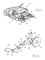
- FIG 1 schematically illustrates a suspension system 10 for a vehicle 12.
- the system 10 generally includes an axle 14 that supports a wheel 16.
- the axle 14 can be articulated in an up/down direction via a lower suspension link 18 and an upper suspension link 20.
- a torsion bar 22 is connected to the lower link 18 at one end and to the vehicle frame 24 by an anchor arm 26 at the other.
- a shock absorber 21 is typically connected between the lower link 18 and the vehicle frame 24.
- the torsion bar 22 twists in response to the articulation of the lower link 18 due to the up/down movement of the axle 14 and wheel 16. In this way, the torsion bar 22 provides elastic resistance to the up/down articulation of the lower link 18.
- one end of the torsion bar 22 is fixed to the lower link 18, and the other end is joined to a cross member 28 of the vehicle frame 24 by the anchor arm 26.
- the twist angle of the torsion bar 22, i.e. an initial load, is adjusted by varying the position of the anchor arm 26 relative to the cross member 28.
- the torsion bar 22 also supports a first adjuster arm 30 and a second adjuster arm 32.
- the first 30 and second 32 adjuster arms are mountable along the length of the torsion bar 22 to contact a first and second stop member 34, 36.
- the stop members 30, 32 can be separate components attachable to the vehicle frame 24 or be integral parts of the vehicle frame 24 itself.
- the adjuster arms 30, 32 extend radially from the torsion bar 22 to respectively contact the stop member 34, 36 when the torsion bar 22 is subjected to a predetermined torsion or twist. That is, the entire torsion bar 22 can be rotated or twisted until a predetermined torsion is reached and the first adjuster arm 30 contacts the first stop 34.
- a length of the torsion bar 22 from the cross member 28 to the first adjuster arm 30 is thereby rotationally fixed.
- the effective length of the torsion bar 22 is thereby reduced to the length from the first adjuster arm 30 to the lower link 18. By reducing the effective length of the torsion bar 22, the effective spring rate of the torsion bar 22 is increased.
- the second adjuster arm 32 contacts the second stop 36.
- a second length of the torsion bar 22 defined from the cross member 28 to the second adjuster arm 32 is rotationally fixed.
- the effective length of the torsion bar 22 is now reduced to the length from the from the second adjuster arm 32 to the lower link 18. Accordingly, because only the length from the second adjuster arm 32 to the lower link 18 can be rotated or twisted, the effective spring rate of the torsion bar 22 is further increased.
- relatively small impacts such as that which occur during a normal straight travelling condition, are absorbable by the entire torsion bar 22 because the first adjuster arm 30 is not in contact with the first stop 34. Because the entire length of the torsion bar is the effective length, the torsion bar provides a relatively soft spring constant. The torsion bar 22 absorbs the vibrations and provides a smooth ride. However, when a predetermined load is applied to the torsion bar, the adjuster arm contacts the stop. The effective length of the torsion bar is reduced and the suspension is accordingly stiffened. The stiffer suspension is thus provided when it is required, such as when cornering, while allowing a smooth ride when it is not required, such as during normal straight travelling.
- the torsion bar 22 is manufactured as a single one-piece bar of a having a constant diameter and the adjuster arms are positioned along the torsion bar to provide the desired spring rates in response to predetermined torsional loads. It will be realized by one skilled in the art, that the number, radial position, and axial position of adjuster arms can be varied to provide desired spring rates and handling characteristics according to the teachings of the present invention.
- the present invention provides a suspension system for a vehicle which can enhance riding comfort and handling by modifying the effective length of the torsion bar to achieve multiple spring constants with a single constant diameter torsion bar. Further, by axially shifting the adjuster arms after installation in the vehicle, the suspension system can be fine tuned.
Abstract
Description
- The present invention relates to a torsion bar assembly for a vehicle suspension system, and more particularly to modifying the effective length of the torsion bar to provide variable effective spring rates.
- Vehicles are commonly equipped with independent suspension systems which can include a vibration or shock absorbing device for absorbing road shock and other vibrations while providing a smooth and comfortable ride for the vehicle occupants. One type of shock absorbing system includes a torsion bar. In suspension systems of this type, the torsion bar extends longitudinally along the length of the vehicle. One end of the torsion bar is connected to a suspension control arm while the other end is fixed to the vehicle frame. The torsion bar twists according to the articulation of the suspension component to provide a torsional elastic resistance to the up/down or jounce/rebound (bump and droop) movement of the suspension component. The torsion bar thereby acts as a spring to absorb vibrations from the road surface and provide particular handling qualities.
- As noted, one end of the torsion bar is attached to the vehicle frame. It is known to provide an adjuster arm to connect the end of the torsion bar to the frame. The adjuster arm allows the torsion bar to be preloaded or twisted to provide a particular spring rate of the torsion bar and thereby tune the suspension characteristics. However, such conventional torsion bar systems are limited to the predefined constant spring rate.
- It is also known to provide a multi-segment torsion bar. Each segment has a different diameter to provide different spring rigidities. A catching protrusion is located at the boundary between each segment. When the torsion bar is subjected to small scale vibrations, the small diameter segment twists and absorbs the vibration. When vibration generate twisting of the torsion bar in excess of the catching protrusion, the small diameter segment becomes rotationally fixed and the relatively larger diameter segment twists to absorb the vibration. However, such a multi-segmented torsion bar is difficult to manufacture as each segment must be securely attached to the other segments to resist the torsional loads. Further, the multi-segment torsion bar is predefined during manufacture to provide particular spring rates based on the diameter and length of the connected segments. This limits the adaptability of the torsion bar and necessarily prevents later fine tuning of the suspension system as the segments are fixed.
- Accordingly, it is desirable to provide a torsion bar suspension, which is relatively uncomplicated to manufacture, and which can provide variable spring rates in a multiple of vehicle applications. It is also desirable to provide a torsion bar suspension which can be fine-tuned after installation in a vehicle.
- The suspension system according to the present invention includes a one-piece torsion bar having at least one adjuster arm. The adjuster arms are mountable along the length of the torsion bar to contact respective stop members. The adjuster arms contact the stop members when the torsion bar is subjected to a predetermined torsion. That is, the entire torsion bar can be twisted until the predetermined torsion is reached and a first adjuster arm contacts a first stop. When the first adjuster arm contacts the first stop, a portion of the torsion bar is rotationally fixed and the effective length of the torsion bar is reduced. By reducing the effective length of the torsion bar, the effective spring rate of the torsion bar is increased. Further, by axially shifting the adjuster arms after installation in the vehicle, the spring rates of the torsion bar and thus the suspension system can be fine-tuned.
- According to the present invention, relatively small vibrations, such as that which occur during a normal straight travelling condition, are absorbable by the entire torsion bar. Because the entire length of the torsion bar is the effective length, a relatively soft spring constant absorbs the vibrations and provides a smooth ride. However, as impact or additional loads are applied to the torsion bar, the effective length of the torsion bar is reduced and the suspension is stiffened.
- The present invention therefore provides a suspension system for a vehicle which can enhance riding comfort and handling by modifying the effective length of the torsion bar to achieve multiple spring constants with a single constant diameter torsion bar.
- The various features and advantages of this invention will become apparent to those skilled in the art from the following detailed description of the currently preferred embodiment. The drawings that accompany the detailed description can be briefly described as follows:
- Figure 1 is a general phantom view of a vehicle suspension system according to the present invention; and
- Figure 2 is an expanded view facing forwardly along a torsion bar according to the present invention.
-
- Figure 1 schematically illustrates a
suspension system 10 for avehicle 12. Thesystem 10 generally includes anaxle 14 that supports awheel 16. Theaxle 14 can be articulated in an up/down direction via alower suspension link 18 and anupper suspension link 20. As can be seen in Figure 2, atorsion bar 22 is connected to thelower link 18 at one end and to thevehicle frame 24 by ananchor arm 26 at the other. To dampen the movement of thelower suspension link 18, ashock absorber 21 is typically connected between thelower link 18 and thevehicle frame 24. In operation, the torsion bar 22 twists in response to the articulation of thelower link 18 due to the up/down movement of theaxle 14 andwheel 16. In this way, thetorsion bar 22 provides elastic resistance to the up/down articulation of thelower link 18. - Referring to Figure 2, one end of the
torsion bar 22 is fixed to thelower link 18, and the other end is joined to across member 28 of thevehicle frame 24 by theanchor arm 26. The twist angle of thetorsion bar 22, i.e. an initial load, is adjusted by varying the position of theanchor arm 26 relative to thecross member 28. - In the disclosed embodiment, the
torsion bar 22 also supports afirst adjuster arm 30 and asecond adjuster arm 32. The first 30 and second 32 adjuster arms are mountable along the length of thetorsion bar 22 to contact a first andsecond stop member stop members vehicle frame 24 or be integral parts of thevehicle frame 24 itself. - The
adjuster arms torsion bar 22 to respectively contact thestop member torsion bar 22 is subjected to a predetermined torsion or twist. That is, theentire torsion bar 22 can be rotated or twisted until a predetermined torsion is reached and thefirst adjuster arm 30 contacts thefirst stop 34. When thefirst adjuster arm 30 contacts thefirst stop 34, a length of thetorsion bar 22 from thecross member 28 to thefirst adjuster arm 30 is thereby rotationally fixed. The effective length of thetorsion bar 22 is thereby reduced to the length from thefirst adjuster arm 30 to thelower link 18. By reducing the effective length of thetorsion bar 22, the effective spring rate of thetorsion bar 22 is increased. - When the
torsion bar 22 is subjected to further torsional loads such that a second predetermined torsion is achieved, thesecond adjuster arm 32 contacts thesecond stop 36. Now, a second length of thetorsion bar 22 defined from thecross member 28 to thesecond adjuster arm 32 is rotationally fixed. The effective length of thetorsion bar 22 is now reduced to the length from the from thesecond adjuster arm 32 to thelower link 18. Accordingly, because only the length from thesecond adjuster arm 32 to thelower link 18 can be rotated or twisted, the effective spring rate of thetorsion bar 22 is further increased. - According to the disclosed embodiment, relatively small impacts, such as that which occur during a normal straight travelling condition, are absorbable by the
entire torsion bar 22 because thefirst adjuster arm 30 is not in contact with thefirst stop 34. Because the entire length of the torsion bar is the effective length, the torsion bar provides a relatively soft spring constant. Thetorsion bar 22 absorbs the vibrations and provides a smooth ride. However, when a predetermined load is applied to the torsion bar, the adjuster arm contacts the stop. The effective length of the torsion bar is reduced and the suspension is accordingly stiffened. The stiffer suspension is thus provided when it is required, such as when cornering, while allowing a smooth ride when it is not required, such as during normal straight travelling. - Preferably, the
torsion bar 22 is manufactured as a single one-piece bar of a having a constant diameter and the adjuster arms are positioned along the torsion bar to provide the desired spring rates in response to predetermined torsional loads. It will be realized by one skilled in the art, that the number, radial position, and axial position of adjuster arms can be varied to provide desired spring rates and handling characteristics according to the teachings of the present invention. - As described above, the present invention provides a suspension system for a vehicle which can enhance riding comfort and handling by modifying the effective length of the torsion bar to achieve multiple spring constants with a single constant diameter torsion bar. Further, by axially shifting the adjuster arms after installation in the vehicle, the suspension system can be fine tuned.
- The foregoing description is exemplary rather than defined by the limitations within.
- Many modifications and variations of the present invention are possible in light of the above teachings. The preferred embodiments of this invention have been disclosed, however, one of ordinary skill in the art would recognize that certain modifications would come within the scope of this invention. It is, therefore, to be understood that within the scope of the appended claims, the invention may be practiced otherwise than as specifically described. For that reason the following claims should be studied to determine the true scope and content of this invention.
Claims (7)
- A suspension system (10) for a vehicle (12) comprising: a suspension member; a torsion bar (22) having a uniform cross-sectional area, said torsion bar having a first segment attached to said suspension member and a second segment attached to a vehicle frame member (24), said torsion bar operable to provide an elastic resistance to said suspension member, said elastic resistance dependant on an effective length of said torsion bar; at least one stop (34) mounted to the vehicle frame; and an adjuster arm (30) fixed to said torsion bar intermediate said vehicle frame member and said suspension member, said adjuster arm engagable with said stop to reduce said effective length of said torsion bar when said torsion bar is subjected to a predetermined torsional force.
- The suspension system as recited in claim 1, wherein said torsion bar is a single continuous member.
- The suspension system as recited in claim 1 or claim 2, wherein said stop is the vehicle frame.
- The suspension system as recited in any preceding claim, further comprising a second adjuster arm (32) engagable with a second stop (36).
- The suspension system as recited in claim 4 wherein the second adjuster arm is fixed to said torsion bar intermediate said vehicle frame member and said suspension member.
- The suspension system as recited in claim 4 or claim 5 wherein said second adjuster arm is engagable with said second stop to reduce said effective length of said torsion bar when said torsion bar is subjected to a predetermined torsional force.
- The suspension system as recited in any preceding claim, wherein said first segment of said torsion bar includes a first end of said torsion bar and said second segment of said torsion bar includes an opposite end of said torsion bar.
Applications Claiming Priority (2)
| Application Number | Priority Date | Filing Date | Title |
|---|---|---|---|
| US09/578,225 US6425594B1 (en) | 2000-05-24 | 2000-05-24 | Torsion bar with multiple arm adjusters for a vehicle suspension system |
| US578225 | 2000-05-24 |
Publications (3)
| Publication Number | Publication Date |
|---|---|
| EP1157864A2 true EP1157864A2 (en) | 2001-11-28 |
| EP1157864A3 EP1157864A3 (en) | 2003-04-09 |
| EP1157864B1 EP1157864B1 (en) | 2006-12-13 |
Family
ID=24311936
Family Applications (1)
| Application Number | Title | Priority Date | Filing Date |
|---|---|---|---|
| EP01304559A Expired - Lifetime EP1157864B1 (en) | 2000-05-24 | 2001-05-23 | Torsion bar with multiple arm adjusters for a vehicle suspension system |
Country Status (4)
| Country | Link |
|---|---|
| US (1) | US6425594B1 (en) |
| EP (1) | EP1157864B1 (en) |
| BR (1) | BR0102807A (en) |
| DE (1) | DE60125090D1 (en) |
Cited By (2)
| Publication number | Priority date | Publication date | Assignee | Title |
|---|---|---|---|---|
| KR100452200B1 (en) * | 2002-04-23 | 2004-10-08 | 현대자동차주식회사 | a suspension system of commercial vehicles |
| CN114435050A (en) * | 2022-03-03 | 2022-05-06 | 贵州翰凯斯智能技术有限公司 | Active suspension, system and control method |
Families Citing this family (4)
| Publication number | Priority date | Publication date | Assignee | Title |
|---|---|---|---|---|
| US6945522B2 (en) * | 2002-04-30 | 2005-09-20 | Meritor Heavy Vehicle Technology, Llc | Multi-rate torsion bar independent suspension spring |
| US20040046336A1 (en) * | 2002-08-21 | 2004-03-11 | Jensen Eric L. | Vehicle suspension system having a torsion spring assembly |
| US20080048371A1 (en) * | 2006-08-24 | 2008-02-28 | Gm Global Technology Operations, Inc. | Indexing attachment mechanism for torsion bars |
| CN101229764B (en) * | 2008-02-23 | 2010-10-20 | 李志东 | Torsion bar type automobile suspension arrangement |
Citations (6)
| Publication number | Priority date | Publication date | Assignee | Title |
|---|---|---|---|---|
| FR809336A (en) * | 1935-08-24 | 1937-03-01 | Tatra Ets | Torsion suspension, in particular for oscillating half-axles |
| DE916259C (en) * | 1949-02-22 | 1954-08-05 | Daimler Benz Ag | Vehicle suspension, in particular for motor vehicles |
| US4152011A (en) * | 1976-10-09 | 1979-05-01 | Honda Giken Kogyo Kabushiki Kaisha | Characteristic compensating device for air springs for automotive suspension use |
| WO1992010375A1 (en) * | 1990-12-12 | 1992-06-25 | Aragonesa De Equipamientos Para Automoviles, S.A. Adepasa | Suspension for vehicles |
| US5244190A (en) * | 1989-10-05 | 1993-09-14 | Mauro Bianchi S.A. | Vehicle wheel suspension method |
| US5687960A (en) * | 1996-04-12 | 1997-11-18 | Hyundai Motor Company | Torsion bar assembly for vehicle suspension system |
Family Cites Families (9)
| Publication number | Priority date | Publication date | Assignee | Title |
|---|---|---|---|---|
| US3706481A (en) * | 1970-05-15 | 1972-12-19 | Goodrich Co B F | Vehicle suspension |
| JPS6125867U (en) * | 1984-07-21 | 1986-02-15 | 彦正 土井 | Photo holder that can be used on both sides |
| US4641856A (en) * | 1985-07-24 | 1987-02-10 | Ford Motor Company | Motor vehicle anti-roll stabilizer system |
| GB8906229D0 (en) * | 1989-03-17 | 1989-05-04 | Gkn Technology Ltd | Vehicle suspension systems |
| US5186216A (en) * | 1990-11-02 | 1993-02-16 | Sulzer Brothers Limited | Torsion rod type picking mechanism for a projectile loom |
| PT100217B (en) * | 1991-04-19 | 1999-05-31 | Dina Autobuses | AN APPROPRIATE REAR SUSPENSION |
| DE4327304C2 (en) * | 1992-08-19 | 2002-09-19 | Yorozu Jidosha Kogyo Kk | Suspension system for a motor vehicle |
| US5538229A (en) * | 1992-10-07 | 1996-07-23 | Ford Motor Company | Anti-rotation apparatus for a vehicle suspension member |
| US5354041A (en) * | 1992-12-30 | 1994-10-11 | Edwards Roger W | Torsion bar stiffener |
-
2000
- 2000-05-24 US US09/578,225 patent/US6425594B1/en not_active Expired - Fee Related
-
2001
- 2001-05-23 DE DE60125090T patent/DE60125090D1/en not_active Expired - Lifetime
- 2001-05-23 EP EP01304559A patent/EP1157864B1/en not_active Expired - Lifetime
- 2001-05-24 BR BR0102807-3A patent/BR0102807A/en not_active IP Right Cessation
Patent Citations (6)
| Publication number | Priority date | Publication date | Assignee | Title |
|---|---|---|---|---|
| FR809336A (en) * | 1935-08-24 | 1937-03-01 | Tatra Ets | Torsion suspension, in particular for oscillating half-axles |
| DE916259C (en) * | 1949-02-22 | 1954-08-05 | Daimler Benz Ag | Vehicle suspension, in particular for motor vehicles |
| US4152011A (en) * | 1976-10-09 | 1979-05-01 | Honda Giken Kogyo Kabushiki Kaisha | Characteristic compensating device for air springs for automotive suspension use |
| US5244190A (en) * | 1989-10-05 | 1993-09-14 | Mauro Bianchi S.A. | Vehicle wheel suspension method |
| WO1992010375A1 (en) * | 1990-12-12 | 1992-06-25 | Aragonesa De Equipamientos Para Automoviles, S.A. Adepasa | Suspension for vehicles |
| US5687960A (en) * | 1996-04-12 | 1997-11-18 | Hyundai Motor Company | Torsion bar assembly for vehicle suspension system |
Cited By (2)
| Publication number | Priority date | Publication date | Assignee | Title |
|---|---|---|---|---|
| KR100452200B1 (en) * | 2002-04-23 | 2004-10-08 | 현대자동차주식회사 | a suspension system of commercial vehicles |
| CN114435050A (en) * | 2022-03-03 | 2022-05-06 | 贵州翰凯斯智能技术有限公司 | Active suspension, system and control method |
Also Published As
| Publication number | Publication date |
|---|---|
| US6425594B1 (en) | 2002-07-30 |
| BR0102807A (en) | 2002-07-23 |
| EP1157864B1 (en) | 2006-12-13 |
| DE60125090D1 (en) | 2007-01-25 |
| EP1157864A3 (en) | 2003-04-09 |
Similar Documents
| Publication | Publication Date | Title |
|---|---|---|
| US6481701B2 (en) | Spring having coils of varying diameters | |
| US7185902B1 (en) | Strut suspension with pivoting rocker arm | |
| KR0139520B1 (en) | Suspension system for a vehicle | |
| US4779893A (en) | Strut type vehicle wheel suspension | |
| AU2004236571A1 (en) | Multi-link rear suspension system | |
| US6530586B2 (en) | Suspension torsion bar with variable rate adjustment arms | |
| US5411285A (en) | Rear suspension for vehicle | |
| US6425594B1 (en) | Torsion bar with multiple arm adjusters for a vehicle suspension system | |
| US6357771B1 (en) | Torsion bar with variable rate anchor arm for a vehicle suspension system | |
| EP0083235B1 (en) | Independent rear wheel suspension | |
| EP1101636A1 (en) | Stabilizing arrangement for vehicle suspensions | |
| US5549321A (en) | Tilt control apparatus for an automotive suspension | |
| US6206391B1 (en) | Rear suspension using a torsional spring integral with trailing arm | |
| Liu | Recent innovations in vehicle suspension systems | |
| KR100616010B1 (en) | Strut assembly for automobile | |
| KR100519091B1 (en) | bush for rear suspension | |
| KR200253064Y1 (en) | Roll compensating system for automotive suspension | |
| KR100293679B1 (en) | Bush system for mounting trailing arm of suspension in vehicle | |
| KR100412844B1 (en) | suspension system for truck | |
| KR100228976B1 (en) | Suspension system for a vehicle | |
| KR200167540Y1 (en) | Rear coil spring and frame connecting structure for a car | |
| KR0139694Y1 (en) | Variable strut bar for a vehicle | |
| KR100737011B1 (en) | suspention system of vehicle | |
| KR19980045482A (en) | Shock absorber of automobile suspension | |
| KR20040033803A (en) | Lower control arm bush for suspension of vehicles |
Legal Events
| Date | Code | Title | Description |
|---|---|---|---|
| PUAI | Public reference made under article 153(3) epc to a published international application that has entered the european phase |
Free format text: ORIGINAL CODE: 0009012 |
|
| AK | Designated contracting states |
Kind code of ref document: A2 Designated state(s): AT BE CH CY DE DK ES FI FR GB GR IE IT LI LU MC NL PT SE TR |
|
| AX | Request for extension of the european patent |
Free format text: AL;LT;LV;MK;RO;SI |
|
| RIN1 | Information on inventor provided before grant (corrected) |
Inventor name: KEENEY, CHRIS Inventor name: HAWKINS, JIM Inventor name: YOLLICK, STEVE Inventor name: FADER, JOE Inventor name: CLEMENTS, MARK |
|
| PUAL | Search report despatched |
Free format text: ORIGINAL CODE: 0009013 |
|
| AK | Designated contracting states |
Kind code of ref document: A3 Designated state(s): AT BE CH CY DE DK ES FI FR GB GR IE IT LI LU MC NL PT SE TR |
|
| AX | Request for extension of the european patent |
Extension state: AL LT LV MK RO SI |
|
| RIC1 | Information provided on ipc code assigned before grant |
Ipc: 7B 60G 11/20 B Ipc: 7B 60G 11/18 A |
|
| 17P | Request for examination filed |
Effective date: 20030926 |
|
| AKX | Designation fees paid |
Designated state(s): DE ES FR GB IT |
|
| 17Q | First examination report despatched |
Effective date: 20040528 |
|
| RAP1 | Party data changed (applicant data changed or rights of an application transferred) |
Owner name: ARVINMERITOR TECHNOLOGY, LLC |
|
| GRAP | Despatch of communication of intention to grant a patent |
Free format text: ORIGINAL CODE: EPIDOSNIGR1 |
|
| GRAS | Grant fee paid |
Free format text: ORIGINAL CODE: EPIDOSNIGR3 |
|
| GRAA | (expected) grant |
Free format text: ORIGINAL CODE: 0009210 |
|
| RIN1 | Information on inventor provided before grant (corrected) |
Inventor name: HAWKINS, JIM Inventor name: FADER, JOE Inventor name: YOLLICK, STEVE Inventor name: CLEMENTS, MARK Inventor name: KEENEY, CHRIS |
|
| AK | Designated contracting states |
Kind code of ref document: B1 Designated state(s): DE ES FR GB IT |
|
| PG25 | Lapsed in a contracting state [announced via postgrant information from national office to epo] |
Ref country code: IT Free format text: LAPSE BECAUSE OF FAILURE TO SUBMIT A TRANSLATION OF THE DESCRIPTION OR TO PAY THE FEE WITHIN THE PRESCRIBED TIME-LIMIT;WARNING: LAPSES OF ITALIAN PATENTS WITH EFFECTIVE DATE BEFORE 2007 MAY HAVE OCCURRED AT ANY TIME BEFORE 2007. THE CORRECT EFFECTIVE DATE MAY BE DIFFERENT FROM THE ONE RECORDED. Effective date: 20061213 |
|
| REG | Reference to a national code |
Ref country code: GB Ref legal event code: FG4D |
|
| REF | Corresponds to: |
Ref document number: 60125090 Country of ref document: DE Date of ref document: 20070125 Kind code of ref document: P |
|
| PG25 | Lapsed in a contracting state [announced via postgrant information from national office to epo] |
Ref country code: DE Free format text: LAPSE BECAUSE OF FAILURE TO SUBMIT A TRANSLATION OF THE DESCRIPTION OR TO PAY THE FEE WITHIN THE PRESCRIBED TIME-LIMIT Effective date: 20070314 |
|
| PG25 | Lapsed in a contracting state [announced via postgrant information from national office to epo] |
Ref country code: ES Free format text: LAPSE BECAUSE OF FAILURE TO SUBMIT A TRANSLATION OF THE DESCRIPTION OR TO PAY THE FEE WITHIN THE PRESCRIBED TIME-LIMIT Effective date: 20070324 |
|
| PGFP | Annual fee paid to national office [announced via postgrant information from national office to epo] |
Ref country code: DE Payment date: 20070517 Year of fee payment: 7 |
|
| EN | Fr: translation not filed | ||
| PLBE | No opposition filed within time limit |
Free format text: ORIGINAL CODE: 0009261 |
|
| STAA | Information on the status of an ep patent application or granted ep patent |
Free format text: STATUS: NO OPPOSITION FILED WITHIN TIME LIMIT |
|
| 26N | No opposition filed |
Effective date: 20070914 |
|
| PGFP | Annual fee paid to national office [announced via postgrant information from national office to epo] |
Ref country code: GB Payment date: 20070523 Year of fee payment: 7 |
|
| PG25 | Lapsed in a contracting state [announced via postgrant information from national office to epo] |
Ref country code: FR Free format text: LAPSE BECAUSE OF FAILURE TO SUBMIT A TRANSLATION OF THE DESCRIPTION OR TO PAY THE FEE WITHIN THE PRESCRIBED TIME-LIMIT Effective date: 20070803 |
|
| PGFP | Annual fee paid to national office [announced via postgrant information from national office to epo] |
Ref country code: FR Payment date: 20070510 Year of fee payment: 7 |
|
| GBPC | Gb: european patent ceased through non-payment of renewal fee |
Effective date: 20080523 |
|
| PG25 | Lapsed in a contracting state [announced via postgrant information from national office to epo] |
Ref country code: GB Free format text: LAPSE BECAUSE OF NON-PAYMENT OF DUE FEES Effective date: 20080523 |