EP1157787A1 - Method for soil and stoneworking and hydraulic impact tool - Google Patents
Method for soil and stoneworking and hydraulic impact tool Download PDFInfo
- Publication number
- EP1157787A1 EP1157787A1 EP00116974A EP00116974A EP1157787A1 EP 1157787 A1 EP1157787 A1 EP 1157787A1 EP 00116974 A EP00116974 A EP 00116974A EP 00116974 A EP00116974 A EP 00116974A EP 1157787 A1 EP1157787 A1 EP 1157787A1
- Authority
- EP
- European Patent Office
- Prior art keywords
- piston
- working
- control
- pistons
- working piston
- Prior art date
- Legal status (The legal status is an assumption and is not a legal conclusion. Google has not performed a legal analysis and makes no representation as to the accuracy of the status listed.)
- Granted
Links
- 238000000034 method Methods 0.000 title claims abstract description 14
- 239000002689 soil Substances 0.000 title description 2
- 230000007246 mechanism Effects 0.000 claims description 16
- 230000035559 beat frequency Effects 0.000 claims description 6
- 230000001360 synchronised effect Effects 0.000 claims description 6
- 239000004575 stone Substances 0.000 claims description 5
- 238000005553 drilling Methods 0.000 description 9
- 239000011435 rock Substances 0.000 description 7
- 238000003780 insertion Methods 0.000 description 6
- 230000037431 insertion Effects 0.000 description 6
- 230000010363 phase shift Effects 0.000 description 2
- 230000001788 irregular Effects 0.000 description 1
- 238000002955 isolation Methods 0.000 description 1
- 238000009527 percussion Methods 0.000 description 1
- 230000035939 shock Effects 0.000 description 1
Images


Classifications
-
- E—FIXED CONSTRUCTIONS
- E21—EARTH OR ROCK DRILLING; MINING
- E21B—EARTH OR ROCK DRILLING; OBTAINING OIL, GAS, WATER, SOLUBLE OR MELTABLE MATERIALS OR A SLURRY OF MINERALS FROM WELLS
- E21B6/00—Drives for drilling with combined rotary and percussive action
- E21B6/02—Drives for drilling with combined rotary and percussive action the rotation being continuous
- E21B6/04—Separate drives for percussion and rotation
-
- B—PERFORMING OPERATIONS; TRANSPORTING
- B25—HAND TOOLS; PORTABLE POWER-DRIVEN TOOLS; MANIPULATORS
- B25D—PERCUSSIVE TOOLS
- B25D9/00—Portable percussive tools with fluid-pressure drive, i.e. driven directly by fluids, e.g. having several percussive tool bits operated simultaneously
- B25D9/04—Portable percussive tools with fluid-pressure drive, i.e. driven directly by fluids, e.g. having several percussive tool bits operated simultaneously of the hammer piston type, i.e. in which the tool bit or anvil is hit by an impulse member
-
- B—PERFORMING OPERATIONS; TRANSPORTING
- B25—HAND TOOLS; PORTABLE POWER-DRIVEN TOOLS; MANIPULATORS
- B25D—PERCUSSIVE TOOLS
- B25D9/00—Portable percussive tools with fluid-pressure drive, i.e. driven directly by fluids, e.g. having several percussive tool bits operated simultaneously
- B25D9/14—Control devices for the reciprocating piston
- B25D9/16—Valve arrangements therefor
- B25D9/20—Valve arrangements therefor involving a tubular-type slide valve
Definitions
- the invention relates to a method for carrying out earth or rock work, where blows from a hydraulic driven piston are exerted on an anvil as well as a hydraulic striking mechanism for implementation such earth and stone work.
- Earth and stone works include drilling in the ground or rock, especially to understand hammer drilling, under also overlay drilling with inner tube rods and Outer tube linkage as well as the operation of rock breakers, at which a work tool in the form of a chisel by blows in rocky rock is driven to break this open.
- Hydraulic striking mechanisms with which the insertion is known a pipe rod for drilling or on the chisel a rock breaker is hit.
- the effectiveness of such Striking mechanism depends on the single impact energy and the Beat frequency.
- a high single impact energy is achieved if the working piston of the striking mechanism has a high mass.
- For Accelerating such masses requires high pressures.
- the mass of the working piston is several kg and the piston stroke is e.g. 35 mm.
- Typical piston speeds are 7 to 11 m / sec.
- the attainable stroke rate is between 250 and 3500 beats / min. Should the single impact energy the mass will usually be enlarged of the working piston increases, which is usually a Reduction in stroke rate.
- a fluid-operated impact hammer is known from DE 43 43 589 C1, where the working piston is controlled by a control piston and hits the plug end of a drill pipe exercises. To do that when pulling back the drill pipe A check piston is provided to knock out the drill pipe, the blows against one of the anvil surface Counterface of the insertion end. Here the Non-return piston only switched on when the working piston is stopped.
- the invention has for its object a method for Perform earthworks or stone work and a hydraulic one To create percussion to increase the effectiveness of the To obtain field processing, i.e. increased drilling or increased crushing performance (when rock breaking).
- the working pistons should be different Hit times on the anvil.
- the movements of the working pistons can be synchronized so that the working pistons operated out of phase with each other, with two For example, the working piston is 180 ° out of phase. This means, that one working piston carries out the stroke, while the other piston is on the return stroke. Phase shifts other than 180 ° are also possible.
- the two working pistons run independently of one another and with different frequencies. It is assumed that usually the blows the working piston are staggered in time and only closed the strokes of both pistons at certain times collapse.
- Another variant of the invention provides that the blows the working piston synchronously, i.e. run at the same time.
- the working pistons must have the same working frequencies and operate without mutual phase shift. It there is also the possibility of providing a striking mechanism in such a way that the working pistons are optionally synchronous and can be operated asynchronously.
- the invention enables a high number of blows (frequency of blows), which keeps the drill pipe in constant motion during drilling (Vibration) is held. Since most floors are grainy Contain part that gets in motion due to the high number of blows, impact drilling results in a very high drilling feed rate.
- bumping can occur with the method according to the invention be prevented from occurring when a blow hits hits a shock wave returning in the drill pipe. Through the high number of strokes the next stroke is always exercised if the returning wave is not yet on the back Has arrived at the end.
- the method according to the invention allows numerous variants of the Control of the at least two working pistons. Both can Working pistons are completely independently controlled, each separately become. Alternatively, control is possible where both working pistons have equal rights or one Control in which one of the working pistons has the master function and the other performs the slave function.
- the anvil acting blows exerted by different working pistons preferably have essentially the same masses. This means that the mass deviation is a maximum of 10% is. However, the masses can change to a greater extent differ from each other, although the mass of the lighter of the working pistons not less than two thirds, preferably not less than three quarters, the mass of heavier piston.
- the anvil 10 consists of the Insertion end of a drilling device, the insertion end with a (not shown) pipe string is connected, which on carries a drill bit at the front end.
- the insertion is with a spline section 11 into which a (not shown) Rotary drive engages to turn the insertion end, which also rotates the pipe string.
- the anvil 10 has a first anvil surface at its front end 12 and spaced therefrom an annular second anvil surface 13 on.
- a shaft 14 stands from the anvil surface 13 backwards. The first is at the end of the shaft 14 Anvil surface 12.
- Working piston AK1 which can be moved in a working cylinder AZ1 is.
- the working piston AK1 is controlled by a control piston SK1, which is in a control cylinder SZ1 is movable.
- the control piston SK1 is a hollow control sleeve, while the working piston AK1 is a full piston.
- a high-pressure line HD leads through the control cylinder SZ1, is supplied via the hydraulic medium at high pressure.
- the Hydraulic medium also fills the hollow interior of the control piston SK1.
- a high-pressure line leads from the control cylinder SZ1 15 to the front end of the working cylinder. AZ1.
- an annular groove 16 is provided, one of which Control line 17 to the rear end of the working cylinder AZ1 leads.
- the annular groove 16 passes alternately through radial bores 18 of the control piston SK1 with the high pressure and via a Control groove 19 on the outside of the working piston SK1 with the Return RL in connection.
- the control groove 19 is constantly in the area of an annular groove 20 connected to the return RL of the control cylinder SZ1.
- a control line 22 leads from the working cylinder AZ1 to Control cylinder SZ1.
- the control line 22 is connected to the high pressure line 15 connected when the working piston AK1 is in the Treatment position (shown in Figure 1), and she is connected to the return line 21 when the working piston AK1 itself when it hits the anvil surface 12 in the front end position.
- This reversal of the control piston a collar B1 of the working piston causes by the working piston.
- Another bundle B2 of the working piston is limited the rear cylinder space into which the control line 17 leads.
- the drive of the working piston AK1 with a forward facing Working stroke is done by the control line 17 High pressure acts on the control surface SF1. That of the control surface SF1 opposite control surface SF2 is smaller than the control surface SF1.
- the control surface SF2 is always that Exposed to high pressure.
- the control surface is SF1 on the return stroke depressurized, so that the working piston AK1 is moved back. In the working stroke, the larger control area SF1 predominates force exerted is the force exerted on the smaller control surface SF2 Drag.
- the control line 22 controls the movement of the control piston SK1 by exerting pressure on the control surface SF3.
- the Control piston SK1 is hydraulically biased towards the left, So in the position that the return stroke of the working piston AK1 corresponds. However, if via the control line 22 the high pressure acts on the control surface SF3, the Control piston SK1 moved to the position shown (right), in which he has the working stroke or stroke stroke of the working piston AK1 causes.
- a second working piston AK2 is additionally provided, the hollow or tubular is aligned and the annular Anvil surface 13 strikes.
- the AK2 working piston is basically formed on its outer surface in the same way like the working piston AK1. It has two opposite directions Control surfaces SF1 and SF2, of which the control surface SF2 is constantly exposed to high pressure during the Pressure that acts on the control surface SF1 through the control piston SK2 is changed.
- the control piston SK2 oversteers the control line 17a, the working piston AK2 and the working piston AK2 controls the control piston via the control line 22a SK2.
- the control piston SK2 is designed in the same way as the control piston SK1. He is also on the high pressure line HD and the return line RL connected.
- the masses of the two control pistons AK1 and AK2 are approximate same size.
- the mass of each piston is between 8 and 30 kg.
- the piston stroke of the working pistons is approximately 35 mm and the working frequency of the working pistons is up to 3500 Beats / min.
- each working piston has its own control piston.
- the movements of the working pistons are therefore not synchronized. Since not to be assumed is that both working pistons are at exactly the same frequency operated, there are irregular impact sequences.
- the two high pressure lines HD in Figure 1 can either on the same high pressure source or to different high pressure sources be connected. It is therefore possible to do both Working piston and the associated control piston with different operate at high pressures.
- the different Pressure sources can also be designed for different amounts of oil his.
- the working piston AK1 and the cylinder AZ1 trained in the same way as in the first embodiment.
- the working piston AK1 strikes the anvil surface 12 of the anvil 10.
- the piston AK2 and the working cylinder AZ2 are in the same way formed as in the first embodiment.
- the working piston AK2 is a ring piston, which is on the ring-shaped anvil surface 13 strikes.
- a separate control piston is with this Embodiment not available because of the working piston AK2 forms the control piston for the working piston AK1, and vice versa.
- the control line 17 of the first working cylinder AZ1 is namely with the control line 22a of the second working cylinder AZ2 connected and the control line 22 of the first working cylinder AZ1 is with the control line 17a of the second working cylinder AZ2 connected.
- the working pistons control themselves mutually and in opposite phases. This means that the working piston AK2 assumes its front end position when the working piston AK1 assumes its rear end position, and that the AK2 working piston is in its rear end position, when the AK1 working piston reaches its front end position occupies.
- the movements of both working pistons are with each other synchronized and out of phase by 180 °. This results in with a steady beat, a beat frequency that is double is as high as the stroke frequency of each individual piston.
- control piston SK is the same Formed like the control piston SK1, but additionally provided with an extension 24.
- the extension 24 contains a control groove 25, which two annular grooves 26,27 of the control cylinder SZ can bridge.
- the annular groove 26 is always with the return line RL connected and the annular groove 27 is with a control line 17b connected, which in turn with the in the control line 17a leading into the working cylinder AZ2 is.
- the control line 17b is alternately radial Bores 28 of the control piston SK pressurized and depressurized by the control groove 25.
- the pressure in the Control line 17b is in phase opposition to the pressure in the control line 17, whereby both working pistons AK1 and AK2 are in phase opposition operated to each other.
- the AK1 working piston also works the control piston SK together to generate an oscillating movement, only co-controlled during the AK2 working piston as slave the control is not affected.
- FIG. 5 largely corresponds that of Fig. 4, so the description below limited to explaining the differences.
- the switching device has three connections A, B, C, where C forms an outlet which is optionally connected to inlet A. or connected to inlet B or depressurized.
- the switching element 34 is in the position in which it is connects inlet B to outlet C. Inlet A is blocked. This means that the control pressure in the Control line 17 both the working piston AK1 and the Working piston AK2 controls, this control synchronously he follows. Both working pistons hit and at the same time together on the shaft 14.
Landscapes
- Engineering & Computer Science (AREA)
- Physics & Mathematics (AREA)
- Fluid Mechanics (AREA)
- Life Sciences & Earth Sciences (AREA)
- Geology (AREA)
- Mining & Mineral Resources (AREA)
- Mechanical Engineering (AREA)
- Environmental & Geological Engineering (AREA)
- General Life Sciences & Earth Sciences (AREA)
- Geochemistry & Mineralogy (AREA)
- Earth Drilling (AREA)
Abstract
Description
Die Erfindung betrifft ein Verfahren zur Durchführung von Erd- oder Gesteinsarbeiten, bei welchem Schläge von einem hydraulisch angetriebenen Arbeitskolben auf einen Amboß ausgeübt werden, sowie ein hydraulisches Schlagwerk zur Durchführung solcher Erd- und Gesteinsarbeiten.The invention relates to a method for carrying out earth or rock work, where blows from a hydraulic driven piston are exerted on an anvil as well as a hydraulic striking mechanism for implementation such earth and stone work.
Unter Erd- und Gesteinsarbeiten sind das Bohren in Erdreich oder Gestein, insbesondere das Schlagbohren zu verstehen, unter anderem auch das Überlagerungsbohren mit Innenrohrgestänge und Außenrohrgestänge sowie auch der Betrieb von Felsbrechern, bei dem ein Arbeitswerkzeug in Form eines Meißels durch Schläge in felsiges Gestein vorgetrieben wird, um dies aufzubrechen.Earth and stone works include drilling in the ground or rock, especially to understand hammer drilling, under also overlay drilling with inner tube rods and Outer tube linkage as well as the operation of rock breakers, at which a work tool in the form of a chisel by blows in rocky rock is driven to break this open.
Bekannt sind hydraulische Schlagwerke, mit denen auf das Einsteckende eines Rohrgestänges zum Bohren oder auf den Meißel eines Felsbrechers geschlagen wird. Die Effektivität eines derartigen Schlagwerks hängt von der Einzelschlagenergie und der Schlagfrequenz ab. Eine hohe Einzelschlagenergie wird erreicht, wenn der Arbeitskolben des Schlagwerks eine hohe Masse hat. Zur Beschleunigung solcher Massen werden hohe Drücke benötigt. In der Praxis beträgt die Masse des Arbeitskolbens mehrere kg und der Kolbenhub beträgt z.B. 35 mm. Typische Kolbengeschwindigkeiten sind 7 bis 11 m/sec. Die erreichbare Schlagfrequenz beträgt zwischen 250 und 3500 Schläge/min. Soll die Einzelschlagenergie vergrößert werden, wird in der Regel die Masse des Arbeitskolbens vergrößert, was jedoch in der Regel eine Verringerung der Schlagfrequenz zur Folge hat.Hydraulic striking mechanisms with which the insertion is known a pipe rod for drilling or on the chisel a rock breaker is hit. The effectiveness of such Striking mechanism depends on the single impact energy and the Beat frequency. A high single impact energy is achieved if the working piston of the striking mechanism has a high mass. For Accelerating such masses requires high pressures. In in practice the mass of the working piston is several kg and the piston stroke is e.g. 35 mm. Typical piston speeds are 7 to 11 m / sec. The attainable stroke rate is between 250 and 3500 beats / min. Should the single impact energy the mass will usually be enlarged of the working piston increases, which is usually a Reduction in stroke rate.
Aus DE 43 43 589 C1 ist ein fluidbetätigter Schlaghammer bekannt, bei dem der Arbeitskolben von einem Steuerkolben gesteuert ist und Schläge auf das Einsteckende eines Bohrgestänges ausübt. Um beim Zurückziehen des Bohrgestänges das Bohrgestänge freizuschlagen, ist ein Rückschlagkolben vorgesehen, der Schläge auf eine der Amboßfläche entgegengerichtete Gegenschlagfläche des Einsteckendes ausübt. Hierbei wird der Rückschlagkolben nur dann eingeschaltet, wenn der Arbeitskolben stillgesetzt ist.A fluid-operated impact hammer is known from DE 43 43 589 C1, where the working piston is controlled by a control piston and hits the plug end of a drill pipe exercises. To do that when pulling back the drill pipe A check piston is provided to knock out the drill pipe, the blows against one of the anvil surface Counterface of the insertion end. Here the Non-return piston only switched on when the working piston is stopped.
Der Erfindung liegt die Aufgabe zugrunde, ein Verfahren zum Durchführen von Erd- oder Gesteinsarbeiten und ein hydraulisches Schlagwerk zu schaffen, um eine höhere Effektivität der Schlagbearbeitung zu erhalten, d.h. einen erhöhten Bohrvortrieb oder eine erhöhte Brechleistung (beim Felsbrechen).The invention has for its object a method for Perform earthworks or stone work and a hydraulic one To create percussion to increase the effectiveness of the To obtain field processing, i.e. increased drilling or increased crushing performance (when rock breaking).
Die Lösung dieser Aufgabe erfolgt bei dem erfindungsgemäßen
Verfahren mit den Merkmalen des Patentanspruchs 1 und bei dem
erfindungsgemäßen hydraulischen Schlagwerk mit den Merkmalen
des Patentanspruchs 8. Hiernach sind mindestens zwei Arbeitskolben
vorgesehen, die Schläge in gleicher Richtung auf den Amboß
ausüben. Der Amboß wird also von zwei Arbeitskolben beaufschlagt,
wobei vorzugsweise die Schläge der Arbeitskolben zeitlich
zueinander versetzt sind. Dabei entsteht eine erhöhte
Schlagfrequenz, ohne dass die Einzelschlagenergie durch Verringerung
der Kolbenmasse verringert wäre.This object is achieved in the case of the invention
Method with the features of
Grundsätzlich sollen die Arbeitskolben zu unterschiedlichen Zeitpunkten auf den Amboß aufschlagen. Die Bewegungen der Arbeitskolben können so synchronisiert sein, dass die Arbeitskolben phasenverschoben zueinander betrieben werden, bei zwei Arbeitskolben beispielsweise um 180° phasenverschoben. Dies bedeutet, dass der eine Arbeitskolben den Schlaghub ausführt, während der andere Arbeitskolben sich auf dem Rückhubweg befindet. Auch andere Phasenverschiebungen als 180° sind möglich. Bei einer anderen Alternative laufen die beiden Arbeitskolben unabhängig voneinander und mit unterschiedlichen Frequenzen. Dabei wird davon ausgegangen, dass normalerweise die Schläge der Arbeitskolben zeitlich zueinander versetzt sind und nur zu bestimmten Zeitpunkten zufällig die Schläge beider Arbeitskolben zusammenfallen.Basically, the working pistons should be different Hit times on the anvil. The movements of the working pistons can be synchronized so that the working pistons operated out of phase with each other, with two For example, the working piston is 180 ° out of phase. This means, that one working piston carries out the stroke, while the other piston is on the return stroke. Phase shifts other than 180 ° are also possible. In another alternative, the two working pistons run independently of one another and with different frequencies. It is assumed that usually the blows the working piston are staggered in time and only closed the strokes of both pistons at certain times collapse.
Eine andere Variante der Erfindung sieht vor, dass die Schläge der Arbeitskolben synchron, d.h. zeitgleich, ausgeführt werden. Die Arbeitskolben müssen hierbei mit gleichen Arbeitsfrequenzen und ohne gegenseitige Phasenverschiebung betrieben werden. Es besteht auch die Möglichkeit, ein Schlagwerk in der Weise vorzusehen, dass die Arbeitskolben wahlweise synchron und asynchron betrieben werden können. Another variant of the invention provides that the blows the working piston synchronously, i.e. run at the same time. The working pistons must have the same working frequencies and operate without mutual phase shift. It there is also the possibility of providing a striking mechanism in such a way that the working pistons are optionally synchronous and can be operated asynchronously.
Die Erfindung ermöglicht eine hohe Schlagzahl (Schlagfrequenz), wodurch beim Bohren das Bohrgestänge in ständiger Bewegung (Vibration) gehalten wird. Da die meisten Böden einen körnigen Anteil enthalten, der durch die hohe Schlagzahl in Bewegung gerät, ergibt sich beim Schlagbohren ein sehr hoher Bohrvorschub. Außerdem können mit dem erfindungsgemäßen Verfahren Prellschläge verhindert werden, die entstehen, wenn ein Schlag auf eine im Bohrgestänge rücklaufende Stoßwelle trifft. Durch die hohe Schlagzahl wird der nächste Schlag immer schon dann ausgeübt, wenn die rücklaufende Welle noch nicht am rückwärtigen Ende angekommen ist.The invention enables a high number of blows (frequency of blows), which keeps the drill pipe in constant motion during drilling (Vibration) is held. Since most floors are grainy Contain part that gets in motion due to the high number of blows, impact drilling results in a very high drilling feed rate. In addition, bumping can occur with the method according to the invention be prevented from occurring when a blow hits hits a shock wave returning in the drill pipe. Through the high number of strokes the next stroke is always exercised if the returning wave is not yet on the back Has arrived at the end.
Das erfindungsgemäße Verfahren erlaubt zahlreiche Varianten der Steuerung der mindestens zwei Arbeitskolben. So können beide Arbeitskolben völlig unabhängig voneinander jeweils separat gesteuert werden. Alternativ hierzu ist eine Steuerung möglich, bei der beide Arbeitskolben gleichberechtigt sind oder eine Steuerung, bei der der eine Arbeitskolben die Master-Funktion und der andere die Slave-Funktion ausübt.The method according to the invention allows numerous variants of the Control of the at least two working pistons. Both can Working pistons are completely independently controlled, each separately become. Alternatively, control is possible where both working pistons have equal rights or one Control in which one of the working pistons has the master function and the other performs the slave function.
Im Rahmen der vorliegenden Erfindung werden die auf den Amboß wirkenden Schläge von verschiedenen Arbeitskolben ausgeübt. Die Arbeitskolben haben vorzugsweise im wesentlichen gleiche Massen. Dies bedeutet, dass die Abweichung der Massen maximal 10 % beträgt. Die Massen können sich jedoch auch in höherem Maße voneinander unterscheiden, wobei allerdings die Masse des leichteren der Arbeitskolben nicht geringer als zwei Drittel, vorzugsweise nicht geringer als drei Viertel, der Masse des schwereren Arbeitskolbens ist. In the context of the present invention, the anvil acting blows exerted by different working pistons. The Working pistons preferably have essentially the same masses. This means that the mass deviation is a maximum of 10% is. However, the masses can change to a greater extent differ from each other, although the mass of the lighter of the working pistons not less than two thirds, preferably not less than three quarters, the mass of heavier piston.
Im folgenden werden unter Bezugnahme auf die Zeichnungen Ausführungsbeispiele der Erfindung näher erläutert.The following are exemplary embodiments with reference to the drawings the invention explained in more detail.
Es zeigen:
- Fig. 1
- eine schematische Darstellung einer ersten Ausführungsform des Schlagwerks mit unabhängig voneinander gesteuerten Arbeitskolben,
- Fig. 2
- eine Ausführungsform, bei der die beiden Arbeitskolben sich gegenseitig steuern,
- Fig. 3
- eine Ausführungsform, bei der der eine Arbeitskolben mit einem Steuerkolben zusammenwirkt und dabei den anderen Arbeitskolben steuert,
- Fig. 4
- eine Ausführungsform, bei der ein Arbeitskolben mit einem Steuerkolben zusammenwirkt, während der Steuerkolben gleichzeitig den anderen Arbeitskolben steuert,
- Fig. 5
- eine ähnliche Ausführungsform wie Fig. 4, jedoch zusätzlich mit einem Umschaltorgan, mit dem eine von mehreren Betriebsarten ausgewählt werden kann, wobei in Fig. 5 eine dieser Betriebsarten dargestellt ist,
- Fig. 6
- das Umschaltorgan von Fig. 5 in einer zweiten Betriebsart und
- Fig. 7
- das Umschaltorgan von Fig. 5 in einer dritten Betriebsart.
- Fig. 1
- 1 shows a schematic representation of a first embodiment of the striking mechanism with independently controlled working pistons,
- Fig. 2
- an embodiment in which the two working pistons control each other,
- Fig. 3
- an embodiment in which one working piston interacts with a control piston and controls the other working piston,
- Fig. 4
- an embodiment in which a working piston interacts with a control piston while the control piston simultaneously controls the other working piston,
- Fig. 5
- 4 shows a similar embodiment to FIG. 4, but additionally with a switching element with which one of several operating modes can be selected, one of these operating modes being shown in FIG. 5,
- Fig. 6
- 5 in a second operating mode and
- Fig. 7
- 5 in a third operating mode.
Bei allen Ausführungsbeispielen besteht der Amboß 10 aus dem
Einsteckende einer Bohrvorrichtung, wobei das Einsteckende mit
einem (nicht dargestellten) Rohrstrang verbunden ist, der am
vorderen Ende eine Bohrkrone trägt. Das Einsteckende ist mit
einem Keilwellenabschnitt 11 versehen, in den ein (nicht dargestellter)
Drehantrieb eingreift, um das Einsteckende zu drehen,
wodurch auch das Rohrgestänge gedreht wird.In all embodiments, the
Der Amboß 10 weist an seinem stirnseitigen Ende eine erste Amboßfläche
12 und im Abstand davon eine ringförmige zweite Amboßfläche
13 auf. Von der Amboßfläche 13 steht ein Schaft 14
nach hinten ab. Am Ende des Schaftes 14 befindet sich die erste
Amboßfläche 12.The
Gemäß Fig. 1 schlägt auf die erste Amboßfläche 12 ein erster
Arbeitskolben AK1, der in einem Arbeitszylinder AZ1 verschiebbar
ist. Die Steuerung des Arbeitskolbens AK1 erfolgt
durch einen Steuerkolben SK1, der in einem Steuerzylinder SZ1
verschiebbar ist. Der Steuerkolben SK1 ist eine hohle Steuerhülse,
während der Arbeitskolben AK1 ein voller Kolben ist.1, a first strikes the
Durch den Steuerzylinder SZ1 führt eine Hochdruckleitung HD,
über die Hydraulikmedium mit hohem Druck zugeführt wird. Das
Hydraulikmedium füllt auch den hohlen Innenraum des Steuerkolbens
SK1. Von dem Steuerzylinder SZ1 führt eine Hochdruckleitung
15 zum vorderen Ende des Arbeitszylinders. AZ1. An dem
Steuerzylinder SZ1 ist eine Ringnut 16 vorgesehen, von der eine
Steuerleitung 17 zum rückwärtigen Ende des Arbeitszylinders AZ1
führt. Die Ringnut 16 gelangt abwechselnd über radiale Bohrungen
18 des Steuerkolbens SK1 mit dem Hochdruck und über eine
Steuernut 19 an der Außenseite des Arbeitskolbens SK1 mit dem
Rücklauf RL in Verbindung. Die Steuernut 19 befindet sich ständig
im Bereich einer mit dem Rücklauf RL verbundenen Ringnut 20
des Steuerzylinders SZ1. Vom Arbeitszylinder AZ1 führt eine
Rücklaufleitung 21 zur Ringnut 20.A high-pressure line HD leads through the control cylinder SZ1,
is supplied via the hydraulic medium at high pressure. The
Hydraulic medium also fills the hollow interior of the control piston
SK1. A high-pressure line leads from the
Ferner führt vom Arbeitszylinder AZ1 eine Steuerleitung 22 zum
Steuerzylinder SZ1. Die Steuerleitung 22 ist mit der Hochdruckleitung
15 verbunden, wenn der Arbeitskolben AK1 sich in der
(in Figur 1 dargestellten) Rückzugsposition befindet, und sie
ist mit der Rücklaufleitung 21 verbunden, wenn der Arbeitskolben
AK1 sich beim Aufschlagen auf die Amboßfläche 12 in der
vorderen Endstellung befindet. Dieses Umsteuern des Steuerkolbens
durch den Arbeitskolben bewirkt ein Bund B1 des Arbeitskolbens.
Ein weiterer Bund B2 des Arbeitskolbens begrenzt
den rückwärtigen Zylinderraum, in den die Steuerleitung 17 hineinführt.Furthermore, a
Der Antrieb des Arbeitskolbens AK1 bei einem nach vorne gerichteten
Arbeitshub erfolgt dadurch, dass durch die Steuerleitung
17 Hochdruck auf die Steuerfläche SF1 einwirkt. Die der Steuerfläche
SF1 entgegengerichtete Steuerfläche SF2 ist kleiner als
die Steuerfläche SF1. Die Steuerfläche SF2 ist ständig dem
Hochdruck ausgesetzt. Beim Rückhub ist die Steuerfläche SF1
drucklos, so dass der Arbeitskolben AK1 zurück bewegt wird.
Beim Arbeitshub überwiegt die auf die größere Steuerfläche SF1
ausgeübte Kraft die auf die kleinere Steuerfläche SF2 ausgeübte
Gegenkraft. The drive of the working piston AK1 with a forward facing
Working stroke is done by the
Die Steuerleitung 22 steuert die Bewegung des Steuerkolbens
SK1, indem ihr Druck auf die Steuerfläche SF3 wirkt. Der
Steuerkolben SK1 ist hydraulisch in Richtung nach links vorgespannt,
also in diejenige Stellung, die dem Rückhub des Arbeitskolbens
AK1 entspricht. Wenn jedoch über die Steuerleitung
22 auf die Steuerfläche SF3 der Hochdruck wirkt, wird der
Steuerkolben SK1 in die dargestellte (rechte) Position verschoben,
in der er den Arbeitshub oder Schlaghub des Arbeitskolbens
AK1 bewirkt.The
Die bis jetzt beschriebene Vorrichtung ist bekannt. Erfindungsgemäß
ist zusätzlich ein zweiter Arbeitskolben AK2 vorgesehen,
der hohl bzw. rohrförmig ausgerichtet ist und auf die ringförmige
Amboßfläche 13 schlägt. Der Arbeitskolben AK2 ist
grundsätzlich an seiner Außenfläche in gleicher Weise ausgebildet
wie der Arbeitskolben AK1. Er weist zwei entgegengerichtete
Steuerflächen SF1 und SF2 auf, von denen die Steuerfläche
SF2 ständig dem Hochdruck ausgesetzt ist, während der
Druck, der auf die Steuerfläche SF1 wirkt, durch den Steuerkolben
SK2 verändert wird. Der Steuerkolben SK2 steuert über
die Steuerleitung 17a den Arbeitskolben AK2 und der Arbeitskolben
AK2 steuert über die Steuerleitung 22a den Steuerkolben
SK2. Der Steuerkolben SK2 ist in gleicher Weise ausgebildet wie
der Steuerkolben SK1. Er ist ebenfalls an die Hochdruckleitung
HD und die Rücklaufleitung RL angeschlossen.The device described so far is known. According to the invention
a second working piston AK2 is additionally provided,
the hollow or tubular is aligned and the
Die Massen der beiden Steuerkolben AK1 und AK2 sind annähernd gleich groß. Die Masse eines jeden Kolbens beträgt zwischen 8 und 30 kg. Der Kolbenhub der Arbeitskolben beträgt etwa 35 mm und die Arbeitsfrequenz der Arbeitskolben beträgt bis zu 3500 Schläge/min. The masses of the two control pistons AK1 and AK2 are approximate same size. The mass of each piston is between 8 and 30 kg. The piston stroke of the working pistons is approximately 35 mm and the working frequency of the working pistons is up to 3500 Beats / min.
Bei dem Ausführungsbeispiel nach Figur 1 hat jeder Arbeitskolben seinen eigenen Steuerkolben. Die Bewegungen der Arbeitskolben sind daher nicht synchronisiert. Da nicht anzunehmen ist, dass beide Arbeitskolben exakt mit der gleichen Frequenz betrieben werden, ergeben sich unregelmäßige Schlagfolgen.In the exemplary embodiment according to FIG. 1, each working piston has its own control piston. The movements of the working pistons are therefore not synchronized. Since not to be assumed is that both working pistons are at exactly the same frequency operated, there are irregular impact sequences.
Die beiden Hochdruckleitungen HD in Figur 1 können entweder an dieselbe Hochdruckquelle oder auch an unterschiedliche Hochdruckquellen angeschlossen werden. Es ist somit möglich, beide Arbeitskolben und die zugehörigen Steuerkolben mit unterschiedlich hohen Drücken zu betreiben. Die unterschiedlichen Druckquellen können auch für unterschiedliche Ölmengen ausgelegt sein.The two high pressure lines HD in Figure 1 can either on the same high pressure source or to different high pressure sources be connected. It is therefore possible to do both Working piston and the associated control piston with different operate at high pressures. The different Pressure sources can also be designed for different amounts of oil his.
Bei dem Ausführungsbeispiel von Figur 2 sind der Arbeitskolben
AK1 und der Arbeitszylinder AZ1 in gleicher Weise ausgebildet
wie bei dem ersten Ausführungsbeispiel. Der Arbeitskolben AK1
schlägt auf die Amboßfläche 12 des Amboß 10. Auch der Arbeitskolben
AK2 und der Arbeitszylinder AZ2 sind in gleicher Weise
ausgebildet wie bei dem ersten Ausführungsbeispiel. Der Arbeitskolben
AK2 ist ein Ringkolben, der auf die ringförmige Amboßfläche
13 schlägt. Ein separater Steuerkolben ist bei diesem
Ausführungsbeispiel nicht vorhanden, weil der Arbeitskolben AK2
den Steuerkolben für den Arbeitskolben AK1 bildet, und umgekehrt.
Die Steuerleitung 17 des ersten Arbeitszylinders AZ1 ist
nämlich mit der Steuerleitung 22a des zweiten Arbeitszylinders
AZ2 verbunden und die Steuerleitung 22 des ersten Arbeitszylinders
AZ1 ist mit der Steuerleitung 17a des zweiten Arbeitszylinders
AZ2 verbunden. Die Arbeitskolben steuern sich
gegenseitig und gegenphasig. Dies bedeutet, dass der Arbeitskolben
AK2 seine vordere Endstellung einnimmt, wenn der Arbeitskolben
AK1 seine rückwärtige Endstellung einnimmt, und
dass der Arbeitskolben AK2 seine rückwärtige Endstellung einnimmt,
wenn der Arbeitskolben AK1 seine vordere Endstellung
einnimmt. Die Bewegungen beider Arbeitskolben sind miteinander
synchronisiert und um 180° phasenverschoben. Damit ergibt sich
bei gleichmäßigem Schlagtakt eine Schlagfrequenz, die doppelt
so hoch ist wie die Schlagfrequenz jedes einzelnen Arbeitskolbens.In the embodiment of Figure 2, the working piston
AK1 and the cylinder AZ1 trained in the same way
as in the first embodiment. The working piston AK1
strikes the
Bei dem Ausführungsbeispiel von Figur 3 ist der Arbeitskolben
AK1 in gleicher Weise ausgebildet wie bei den übrigen
Ausführungsbeispielen, jedoch ist er mit einer zusätzlichen
Steuernut 30 versehen, die in Abhängigkeit von der Stellung des
Arbeitskolbens entweder mit einer Druckleitung 31 oder mit
einer Rücklaufleitung 32 in Verbindung steht. Durch Umschaltung
bzw. Vertauschung der Leitungen 31,32 kann die Phasenlage des
Arbeitskolbens AK2 in Bezug auf den Arbeitskolben AK1 umgekehrt
werden. Andererseits kann durch Unterbrechung bzw. Absperrung
der Druckleitung 31 der Arbeitskolben AK2 stillgesetzt werden.
Es ist auch möglich, die Leitung 31 an eine separate (andere)
Hochdruckquelle anzuschließen. Auf diese Weise kann der Arbeitskolben
AK2 mit einer anderen Druckquelle betrieben werden,
wie der Arbeitskolben AK1 und der Steuerkolben SK1. Es ist auch
möglich, dass die andere Druckquelle eine unterschiedliche Ölmenge
pro Zeiteinheit liefert. Die Möglichkeit die Arbeitskolben
mit getrennten Druckquellen zu betreiben, erhöht die
Vielseitigkeit des Schlagwerks. Vom Bereich der Steuernut 30
geht eine Steuerleitung 17a aus dem Arbeitszylinder AZ1 heraus.
Diese Steuerleitung führt in den Arbeitszylinder AZ2, um die
Steuerfläche SF3 des Arbeitskolbens AK2 mit Druck zu beaufschlagen
oder drucklos zu machen. Bei diesem Ausführungsbeispiel
bildet der Arbeitskolben AK1 mit dem Steuerkolben SK1
wiederum eine frequenzbestimmende Rückkopplungsschaltung, während
der Arbeitskolben AK2 als Slave von dem Arbeitskolben AK1
mitgesteuert wird.In the embodiment of Figure 3 is the working piston
AK1 trained in the same way as the rest
Embodiments, but it is with an
Bei dem Ausführungsbeispiel von Figur 4 steuert eine Steuerhülse
SK den ersten Arbeitskolben AK1 in gleicher Weise wie bei
dem Beispiel von Figur 1. Der Steuerkolben SK ist in gleicher
Weise ausgebildet wie der Steuerkolben SK1, jedoch zusätzlich
mit einer Verlängerung 24 versehen. Die Verlängerung 24 enthält
eine Steuernut 25, welche zwei Ringnuten 26,27 des Steuerzylinders
SZ überbrücken kann. Die Ringnut 26 ist ständig mit
der Rücklaufleitung RL verbunden und die Ringnut 27 ist mit
einer Steuerleitung 17b verbunden, welche wiederum mit der in
den Arbeitszylinder AZ2 hineinführenden Steuerleitung 17a verbunden
ist. Die Steuerleitung 17b wird abwechselnd über radiale
Bohrungen 28 des Steuerkolbens SK mit Druck beaufschlagt und
durch die Steuernut 25 drucklos gemacht. Der Druck in der
Steuerleitung 17b ist gegenphasig zu dem Druck in der Steuerleitung
17, wodurch beide Arbeitskolben AK1 und AK2 gegenphasig
zueinander betrieben werden. Der Arbeitskolben AK1 wirkt mit
dem Steuerkolben SK zur Erzeugung einer Schwingbewegung zusammen,
während der Arbeitskolben AK2 als Slave lediglich mitgesteuert
wird, die Steuerung aber nicht beeinflußt.In the embodiment of Figure 4 controls a control sleeve
SK the first working piston AK1 in the same way as for
the example of Figure 1. The control piston SK is the same
Formed like the control piston SK1, but additionally
provided with an
Alternativ zu dem anhand von Figur 4 beschriebenen Ausführungsbeispiel
ist es auch möglich, den Arbeitskolben AK2 in Phase
zum Arbeitskolben AK1 zu betreiben. Hierzu müßte die Steuerleitung
17b abgesperrt und die Steuerleitung 17 mit der Steuerleitung
17a verbunden werden. Bei einem gleichphasigen
Synchronbetrieb ist zwar die Schlagfrequenz relativ gering, die
Einzelschlagenergie aber um so größer.As an alternative to the exemplary embodiment described with reference to FIG. 4
it is also possible to phase the working piston AK2
to operate the working piston AK1. The control line would have to do this
17b shut off and the
Es ist auch möglich, zwischen beiden Betriebsarten umzuschalten, um beispielsweise mit niederfrequenten Schlägen von hoher Einzelschlagenergie Felspartien zu zertrümmern, im normalen Erdreich aber mit hoher Schlagfrequenz und geringer Einzelschlagenergie zu arbeiten.It is also possible to switch between the two operating modes switch, for example with low-frequency beats of high single impact energy to smash rock areas in normal soil but with high impact frequency and less Single impact energy to work.
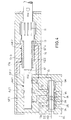
Das Ausführungsbeispiel von Fig. 5 entspricht weitgehend demjenigen von Fig. 4, so dass die nachfolgende Beschreibung sich auf die Erläuterung der Unterschiede beschränkt.The embodiment of FIG. 5 largely corresponds that of Fig. 4, so the description below limited to explaining the differences.
Gemäß Fig. 5 sind die Steuerleitungen 17, 17a und 17b mit einem
Umschaltorgan 34 verbunden, bei dem es sich um ein Wegeventil
handelt. Das Umschaltorgan hat drei Anschlüsse A,B,C, wobei C
einen Auslaß bildet, der wahlweise mit dem Einlaß A verbunden
oder mit dem Einlaß B verbunden oder drucklos gemacht wird.5, the
In Fig. 5 steht das Umschaltorgan 34 in der Stellung, in der es
den Einlaß B mit dem Auslaß C verbindet. Der Einlaß A ist
abgeblockt. Dies bedeutet, dass der Steuerdruck in der
Steuerleitung 17 sowohl den Arbeitskolben AK1 als auch den
Arbeitskolben AK2 steuert, wobei diese Steuerung synchron
erfolgt. Beide Arbeitskolben schlagen also gleichzeitig und
gemeinsam auf den Schaft 14.5, the switching
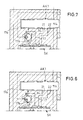
Wenn das Umschaltorgan 34 sich in der Stellung gemäß Fig. 6
befindet, verbindet es den Einlaß A mit dem Auslaß C. Der
Einlaß B ist abgeblockt. Da an den Steuerleitungen 17,17b
jeweils zueinander inverse Drücke anliegen, werden die beiden
Arbeitskolben AK1 und AK2 gegenphasig zueinander betrieben. Die
Schlagfrequenz ist also gegenüber derjenigen eines einzelnen
Arbeitskolbens verdoppelt.When the switching
In der Stellung es Umschaltorgans 34 gemäß Fig. 7 sind die
Einlässe A und B des Umschaltorgans abgeblockt, während der
Auslaß C mit dem Rücklauf verbunden ist. Dadurch wird die
Steuerleitung 17a drucklos und der Arbeitskolben AK2 wird
stillgesetzt. Es arbeitet nur der Arbeitskolben AK1 aufgrund
der Steuerung mittels Steuerleitung 17.7 are the
Inlets A and B of the switching device blocked during the
Outlet C is connected to the return. This will make the
Gemäß Fig. 5 sind die Druckleitungen 15, die in die beiden
Arbeitszylinder AZ1 und AZ2 hineinführen, jeweils mit einem
eigenen Gasdruckspeicher 36 bzw. 37 verbunden, so dass die
Arbeitskolben sich nicht gegenseitig den Druck fortnehmen.
Außerdem ist die Rücklaufleitung RL an einen Gasdruckspeicher
38 angeschlossen.5, the pressure lines 15, which are in the two
Insert cylinder AZ1 and AZ2, each with one
own
Claims (15)
dadurch gekennzeichnet, dass mit mindestens zwei gleichzeitig betriebenen Arbeitskolben (AK1,AK2) Schläge in gleicher Richtung auf den Amboß (10) ausgeübt werden.Method for performing earthworks or stone work, in which blows are exerted by a hydraulically driven working piston on an anvil (10),
characterized in that blows in the same direction are exerted on the anvil (10) with at least two working pistons (AK1, AK2) operated simultaneously.
Priority Applications (2)
| Application Number | Priority Date | Filing Date | Title |
|---|---|---|---|
| EP02025773A EP1291487A1 (en) | 2000-05-18 | 2000-08-08 | Method for soil and stoneworking and hydraulic impact tool |
| US09/854,460 US6557652B2 (en) | 2000-05-18 | 2001-05-15 | Method for performing ground or rock work and hydraulic percussion device |
Applications Claiming Priority (2)
| Application Number | Priority Date | Filing Date | Title |
|---|---|---|---|
| DE10024505A DE10024505A1 (en) | 2000-05-18 | 2000-05-18 | Process for carrying out earthworks or stone work and hydraulic hammer mechanism |
| DE10024505 | 2000-05-18 |
Related Child Applications (1)
| Application Number | Title | Priority Date | Filing Date |
|---|---|---|---|
| EP02025773A Division EP1291487A1 (en) | 2000-05-18 | 2000-08-08 | Method for soil and stoneworking and hydraulic impact tool |
Publications (2)
| Publication Number | Publication Date |
|---|---|
| EP1157787A1 true EP1157787A1 (en) | 2001-11-28 |
| EP1157787B1 EP1157787B1 (en) | 2003-07-02 |
Family
ID=7642620
Family Applications (2)
| Application Number | Title | Priority Date | Filing Date |
|---|---|---|---|
| EP02025773A Withdrawn EP1291487A1 (en) | 2000-05-18 | 2000-08-08 | Method for soil and stoneworking and hydraulic impact tool |
| EP00116974A Expired - Lifetime EP1157787B1 (en) | 2000-05-18 | 2000-08-08 | Method for soil and stoneworking and hydraulic impact tool |
Family Applications Before (1)
| Application Number | Title | Priority Date | Filing Date |
|---|---|---|---|
| EP02025773A Withdrawn EP1291487A1 (en) | 2000-05-18 | 2000-08-08 | Method for soil and stoneworking and hydraulic impact tool |
Country Status (2)
| Country | Link |
|---|---|
| EP (2) | EP1291487A1 (en) |
| DE (2) | DE10024505A1 (en) |
Cited By (5)
| Publication number | Priority date | Publication date | Assignee | Title |
|---|---|---|---|---|
| WO2003039814A1 (en) * | 2001-11-07 | 2003-05-15 | Sandvik Tamrock Oy | Percussion device with a control valve for two alternately striking pistons |
| WO2003074834A1 (en) * | 2002-03-05 | 2003-09-12 | Andrea Tonti | Drill equipped with vibrating hammer with eccentric masses for tool support |
| EP2069602A1 (en) * | 2006-10-02 | 2009-06-17 | Atlas Copco Rock Drills AB | Percussion device and rock drilling machine |
| EP2704880A1 (en) * | 2011-05-03 | 2014-03-12 | Atlas Copco Rock Drills AB | A striker member, and a drilling machine comprising a striker member |
| CN109414809A (en) * | 2016-06-28 | 2019-03-01 | 古河凿岩机械有限公司 | Dual-active plunger type hydraulic impact device |
Families Citing this family (2)
| Publication number | Priority date | Publication date | Assignee | Title |
|---|---|---|---|---|
| SE530781C2 (en) * | 2007-01-11 | 2008-09-09 | Atlas Copco Rock Drills Ab | Rock drilling equipment and method associated with this |
| CN103352895B (en) * | 2013-06-28 | 2015-08-26 | 山河智能装备股份有限公司 | A kind of hydraulic impactor |
Citations (2)
| Publication number | Priority date | Publication date | Assignee | Title |
|---|---|---|---|---|
| US5647445A (en) * | 1995-11-22 | 1997-07-15 | National Research Council Of Canada | Double piston in-the-hole hydraulic hammer drill |
| WO1998031509A1 (en) * | 1997-01-20 | 1998-07-23 | Francesco Verardi | Fluid operated hammer |
-
2000
- 2000-05-18 DE DE10024505A patent/DE10024505A1/en not_active Withdrawn
- 2000-08-08 DE DE50002726T patent/DE50002726D1/en not_active Expired - Fee Related
- 2000-08-08 EP EP02025773A patent/EP1291487A1/en not_active Withdrawn
- 2000-08-08 EP EP00116974A patent/EP1157787B1/en not_active Expired - Lifetime
Patent Citations (2)
| Publication number | Priority date | Publication date | Assignee | Title |
|---|---|---|---|---|
| US5647445A (en) * | 1995-11-22 | 1997-07-15 | National Research Council Of Canada | Double piston in-the-hole hydraulic hammer drill |
| WO1998031509A1 (en) * | 1997-01-20 | 1998-07-23 | Francesco Verardi | Fluid operated hammer |
Cited By (12)
| Publication number | Priority date | Publication date | Assignee | Title |
|---|---|---|---|---|
| WO2003039814A1 (en) * | 2001-11-07 | 2003-05-15 | Sandvik Tamrock Oy | Percussion device with a control valve for two alternately striking pistons |
| CN100410025C (en) * | 2001-11-07 | 2008-08-13 | 山特维克坦罗克有限公司 | Percussion device with a control valve for two alternately striking pistons |
| US7464635B2 (en) | 2001-11-07 | 2008-12-16 | Sandvik Mining And Construction Oy | Percussion device with a control valve for two alternately striking pistons |
| WO2003074834A1 (en) * | 2002-03-05 | 2003-09-12 | Andrea Tonti | Drill equipped with vibrating hammer with eccentric masses for tool support |
| EP2069602A1 (en) * | 2006-10-02 | 2009-06-17 | Atlas Copco Rock Drills AB | Percussion device and rock drilling machine |
| EP2069602A4 (en) * | 2006-10-02 | 2009-11-04 | Atlas Copco Rock Drills Ab | Percussion device and rock drilling machine |
| US9016396B2 (en) | 2006-10-02 | 2015-04-28 | Atlas Copco Rock Drills Ab | Percussion device and rock drilling machine |
| EP2704880A1 (en) * | 2011-05-03 | 2014-03-12 | Atlas Copco Rock Drills AB | A striker member, and a drilling machine comprising a striker member |
| EP2704880A4 (en) * | 2011-05-03 | 2014-09-17 | Atlas Copco Rock Drills Ab | A striker member, and a drilling machine comprising a striker member |
| US9937613B2 (en) | 2011-05-03 | 2018-04-10 | Atlas Copco Rock Drills Ab | Striker member, and a drilling machine comprising a striker member |
| CN109414809A (en) * | 2016-06-28 | 2019-03-01 | 古河凿岩机械有限公司 | Dual-active plunger type hydraulic impact device |
| CN109414809B (en) * | 2016-06-28 | 2022-04-15 | 古河凿岩机械有限公司 | Double-piston type hydraulic impact device |
Also Published As
| Publication number | Publication date |
|---|---|
| DE10024505A1 (en) | 2001-11-29 |
| EP1157787B1 (en) | 2003-07-02 |
| DE50002726D1 (en) | 2003-08-07 |
| EP1291487A1 (en) | 2003-03-12 |
Similar Documents
| Publication | Publication Date | Title |
|---|---|---|
| EP0133161B1 (en) | Method and device for damping the recoil of percussion tools | |
| EP1769131B1 (en) | Drill head for a ground-boring device | |
| EP1632637B1 (en) | Soil working tool and method for introducing a working element into the soil | |
| DE4343589C1 (en) | Fluid operated hammer | |
| DE3710162C1 (en) | Ram boring machine with movable chisel | |
| DE19833650A1 (en) | Hand drill | |
| DE2157259B1 (en) | Ram drilling rig | |
| DE1940836C3 (en) | Hydraulic impact or rotary percussion drill | |
| DE2343079C2 (en) | Device for the substantially horizontal piercing of a dam or the like. | |
| EP0494408B1 (en) | Method and device for enlarging a well | |
| DE2645213A1 (en) | IMPACT TOOL | |
| DE2217507B1 (en) | Hydraulic hammer and its use for hammer drill | |
| DE2630091A1 (en) | METHOD AND DEVICE FOR BREAKING A HARD COMPACT MATERIAL, IN PARTICULAR A ROCK | |
| DE4225701C1 (en) | Rotary drilling appts. with percussion capability - has two coaxial strings with variable rotational speed and direction | |
| EP1157787A1 (en) | Method for soil and stoneworking and hydraulic impact tool | |
| DE3124524C2 (en) | Ramming device for self-propelled pneumatic ram drilling rigs | |
| DE3523219C1 (en) | Hydraulic excavator | |
| DE976583C (en) | Differential hammer piston for pneumatic hammer drill or the like. | |
| DE3842891A1 (en) | ROTATIONAL DRILLING METHOD AND ROTATIONAL DRILLING DEVICE FOR CARRYING OUT THE METHOD | |
| EP0273974B1 (en) | Device for making holes in ground | |
| DE3590831C2 (en) | Damping device for percussion hammers of devices for excavating mines in hard rock | |
| DE4415281C2 (en) | Fluid-operated hammer with reversible direction of impact | |
| EP0731248A1 (en) | Percussion tool | |
| EP0723492B1 (en) | Percussion element | |
| DE102008036722B4 (en) | Method, apparatus and drill head for introducing a hole in the soil |
Legal Events
| Date | Code | Title | Description |
|---|---|---|---|
| PUAI | Public reference made under article 153(3) epc to a published international application that has entered the european phase |
Free format text: ORIGINAL CODE: 0009012 |
|
| 17P | Request for examination filed |
Effective date: 20010301 |
|
| AK | Designated contracting states |
Kind code of ref document: A1 Designated state(s): AT BE CH CY DE DK ES FI FR GB GR IE IT LI LU MC NL PT SE Kind code of ref document: A1 Designated state(s): DE |
|
| AX | Request for extension of the european patent |
Free format text: AL;LT;LV;MK;RO;SI |
|
| AKX | Designation fees paid |
Free format text: DE |
|
| GRAH | Despatch of communication of intention to grant a patent |
Free format text: ORIGINAL CODE: EPIDOS IGRA |
|
| GRAH | Despatch of communication of intention to grant a patent |
Free format text: ORIGINAL CODE: EPIDOS IGRA |
|
| GRAA | (expected) grant |
Free format text: ORIGINAL CODE: 0009210 |
|
| AK | Designated contracting states |
Designated state(s): DE |
|
| REF | Corresponds to: |
Ref document number: 50002726 Country of ref document: DE Date of ref document: 20030807 Kind code of ref document: P |
|
| PGFP | Annual fee paid to national office [announced via postgrant information from national office to epo] |
Ref country code: DE Payment date: 20031010 Year of fee payment: 4 |
|
| PLBE | No opposition filed within time limit |
Free format text: ORIGINAL CODE: 0009261 |
|
| STAA | Information on the status of an ep patent application or granted ep patent |
Free format text: STATUS: NO OPPOSITION FILED WITHIN TIME LIMIT |
|
| 26N | No opposition filed |
Effective date: 20040405 |
|
| PG25 | Lapsed in a contracting state [announced via postgrant information from national office to epo] |
Ref country code: DE Free format text: LAPSE BECAUSE OF NON-PAYMENT OF DUE FEES Effective date: 20050301 |