EP1157670A1 - Zahnärztliches Handstück mit Mitteln zum Verspannen einer Griffhülse mit einem Kopfteil - Google Patents
Zahnärztliches Handstück mit Mitteln zum Verspannen einer Griffhülse mit einem Kopfteil Download PDFInfo
- Publication number
- EP1157670A1 EP1157670A1 EP01112527A EP01112527A EP1157670A1 EP 1157670 A1 EP1157670 A1 EP 1157670A1 EP 01112527 A EP01112527 A EP 01112527A EP 01112527 A EP01112527 A EP 01112527A EP 1157670 A1 EP1157670 A1 EP 1157670A1
- Authority
- EP
- European Patent Office
- Prior art keywords
- head part
- grip sleeve
- dental handpiece
- sleeve
- handpiece according
- Prior art date
- Legal status (The legal status is an assumption and is not a legal conclusion. Google has not performed a legal analysis and makes no representation as to the accuracy of the status listed.)
- Granted
Links
- 230000008878 coupling Effects 0.000 claims description 18
- 238000010168 coupling process Methods 0.000 claims description 18
- 238000005859 coupling reaction Methods 0.000 claims description 18
- 230000000284 resting effect Effects 0.000 claims description 2
- 238000007789 sealing Methods 0.000 description 5
- 230000000712 assembly Effects 0.000 description 1
- 238000000429 assembly Methods 0.000 description 1
- 238000010276 construction Methods 0.000 description 1
- 230000003993 interaction Effects 0.000 description 1
- 238000003754 machining Methods 0.000 description 1
- 238000004519 manufacturing process Methods 0.000 description 1
- 125000006850 spacer group Chemical group 0.000 description 1
- 230000007704 transition Effects 0.000 description 1
Images


Classifications
-
- A—HUMAN NECESSITIES
- A61—MEDICAL OR VETERINARY SCIENCE; HYGIENE
- A61C—DENTISTRY; APPARATUS OR METHODS FOR ORAL OR DENTAL HYGIENE
- A61C1/00—Dental machines for boring or cutting ; General features of dental machines or apparatus, e.g. hand-piece design
- A61C1/08—Machine parts specially adapted for dentistry
-
- A—HUMAN NECESSITIES
- A61—MEDICAL OR VETERINARY SCIENCE; HYGIENE
- A61C—DENTISTRY; APPARATUS OR METHODS FOR ORAL OR DENTAL HYGIENE
- A61C1/00—Dental machines for boring or cutting ; General features of dental machines or apparatus, e.g. hand-piece design
- A61C1/08—Machine parts specially adapted for dentistry
- A61C1/18—Flexible shafts; Clutches or the like; Bearings or lubricating arrangements; Drives or transmissions
Definitions
- the invention relates to a dental handpiece, comprising a head part and a grip sleeve resting thereon and means for tightening the grip sleeve with the headboard.
- a handpiece is known from EP-A-0 753 286, at a grip sleeve between a head part and a arranged on the end of the handle sleeve disc by means an inherently stiff inside the grip sleeve Support structure is clamped. The sits Grip sleeve on the disc and is over this Disc braced against the support structure.
- the object of the invention is a handpiece to provide, which is even simpler and nevertheless has sufficient stability.
- the head part arranged at an angle to the support part such that there is a dental contra-angle.
- the connecting means to a central axis the handpiece arranged at an angle.
- the angle of the contra-angle and the angle of the connecting means different, in particular the angle of the lanyard is smaller than the angle of the contra-angle. This will make a better one Distribution of forces achieved.
- the seal through the connecting means can be placed under prestress, the headboard is both with the same lanyard connected to the grip sleeve as well as the seal of the head part against the grip sleeve.
- the seal is advantageously after assembly under tension to the required sealing forces to apply.
- the Grip sleeve connecting means for connection to a Outer sleeve, in particular the outer sleeve of a coupling part on. This increases the rigidity of the grip sleeve exploited.
- the carrier part is advantageously via connecting means connectable with a coupling part.
- connecting means connectable with a coupling part.
- the carrier part with the coupling part a independently manageable unit forms the individual assemblies of the handpiece in simpler Connect way together when assembling.
- locking means in particular locking openings on the carrier part and corresponding locking means, in particular Locking projections on the coupling part, when assembling snap together, the assembly will favored.
- a further development according to the invention provides that between the headboard and the grip sleeve are secured against rotation is arranged. This will twist the Grip sleeve opposite the headboard and thus one Rotation of the in the grip sleeve and in supply lines held to the carrier part, in particular of the light guide prevented.
- the anti-rotation lock is advantageously sealed, preferably by means of between the head part and Grip sleeve arranged seal to an outlet of the Care product or the return air Prevent dirt in the interior of the grip sleeve.
- the use of the existing seal between Headboard and grip sleeve avoid additional Expenditure.
- the anti-rotation device can be used as a tongue and groove connection between a shaft of the headboard and one end of the Handle sleeve be formed, preferably the groove arranged in the grip sleeve and the spring in the shaft is.
- this can be used as a radial seal be trained.
- the seal is on the inside on an outer surface of a shaft of the head part the seal lies on and on its outside Inner surface of the grip sleeve, the seal in the axial direction to an axial stop of the head part and / or to an axial stop of the handle is spaced. This ensures that the Seal is not loaded in the axial direction, but only in the radial direction under tension is set.
- the elastic at its light exit point in the head part held and sealed against the headboard and the grip sleeve is. Furthermore, there is one inside the grip sleeve arranged, to be adjusted from the carrier part Adjustment means for the position of a light exit surface of the light guide with respect to the outer contour of the grip sleeve provided at the light exit point.
- the adjustment device is against the headboard and / or an extension of the head part in the grip sleeve held longitudinally displaceable and by means of an adjusting device changeable in their position with respect to the head part.
- the change in location is such that the location the light exit surface of the light guide in its Angular position and thus at a distance from the outer wall of the Handle sleeve is changed.
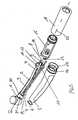
- Fig. 1 is a dental handpiece according to the Invention shown as an exploded view.
- the dental handpiece comprises a head part (1) which supply lines (2,3,4) are connected are covered by a grip sleeve (5). Between the head part (1) and the grip sleeve (5) a seal (6) arranged, the interior of the Grip sleeve (5) with the supply lines inside (2,3,4) seals.
- a light guide is still inside the grip sleeve (5) (7) and connecting means (8,9) in the form of Tensioning screws arranged in a support part (10), together with the supply lines (2,3,4) are held.
- the carrier part (10) has two opposite one another Locking openings (11, 12) with locking projections (13, 14) of a coupling part (15) interact.
- the coupling part (15) can be this snap connection attach to the carrier part (10).
- the grip sleeve (5) faces away from the head part (1) End a thread (16) and another seal (17) on with one over the coupling piece (15) cooperate towards sliding outer sleeve (18).
- a spacer (19) provided, in addition, on a shaft (29) of the Head part (1), which from one end of the grip sleeve (5) is enclosed, a groove (21) for receiving the sealing ring (6) and another groove (22) for receiving a Tongue provided with a corresponding groove interacts within the grip sleeve (5) and one Anti-twist protection of the grip sleeve against the head part (1) represents.
- the dental handpiece is a Elbow, that is, the head part (1) is opposite angled along a longitudinal axis (23).
- Fig. 2 is a longitudinal section through an assembled dental handpiece shown. It can be seen First the handpiece is designed as an elbow, the head part (1) relative to the central axis (23) of the handpiece is angled by an angle ⁇ . This has the consequence that the axis of rotation (24) of the, not shown, machining tool held in the head part (1) is arranged obliquely to the central axis (23).
- the head part (1) is at the tapered end of the tapered Handle sleeve (5) arranged and takes in his Shaft (20), the supply line (2) and the light guide (7) with the light exit point (25).
- the Light guide (7) is in the area of the light exit points (25) sealed by an elastic component (26) and held.
- the light guide (7) is against the holder (19) supported on the back, the holder (19) itself longitudinally slidable along that in that area formed as a rigid tube supply line (2) is performed. This allows the distance of the Light exit point (25) to the central axis (27) of the head part to adjust.
- the adjustment means for the holder (19) are not shown, but they can be considered as in Carrier part (10) held set screws executed his. Pre-positioning and fastening are also possible possible possible by friction or form fit.
- the sealing ring (6) is arranged on the shaft (20) of the head part (1).
- Carrier part (10) arranged in which the light guide (7) and the supply line (2) are guided.
- the connecting means (9) is in the carrier part (10) held, as will be explained later.
- the carrier part (10) is supported against the grip sleeve (5) and lies on an inside of the grip sleeve (5) Projection (28).
- Fig. 3 is a section along the longitudinal axis of the connecting means (8) shown in FIG. 1. It it can be seen that the connecting means (8) in a corresponding bore (29) of the shaft (20) by means of a thread is screwed in.
- the other end of the Connection means (8) is designed as a screw head and held in the carrier part (10).
- the lanyard (8) is arranged in its position so that the end arranged in the carrier part (10) below the Central axis (23) and that screwed into the shaft (20) End lies above the central axis (23).
- the angle, in which the connecting means (8) runs differs nonetheless from the angle of the contra-angle such that the connecting means in a smaller Angle to the central axis (23) stands as the angle of the contra-angle.
- the shaft (20) a ball (30) is arranged to prevent rotation the grip sleeve (5) against the head part (1) or ensures the shaft (20). How it works will be explained below.
- FIG. 4 is an enlargement of the head part 19 with the adjoining shaft 20 in partially broken Representation shown as a section through the ball (30).
- a first groove for receiving is in the shaft (20) the seal (6) at the transition of the handle (5) to the head part (1) in which the seal (6) between the outer end of the grip sleeve (5) and the Head part (1) or the shaft (29) arranged is.
- a ball (30) is spaced as an example of a spring a tongue and groove connection in a recess (22) recessed and is preferably slightly jammed to falling out when disassembling the head piece (1) and the grip sleeve (5) a groove (31) is incorporated, which is opposite the ball (30) and into the the ball (30) partially protrudes.
- the groove (31) extends up to the end of the grip sleeve (5) on which the sealing ring (6) rests. Based on the shown here Presentation is self-evident that twisting the grip sleeve (5) against the head part (1) on the positive connection the groove (31) with that held in the recess (22) Ball (30) is prevented.
- Fig. 5 the principle of the anti-rotation is in interaction with the seal (6) between the grip sleeve (5) and the head part (1) or the shaft (20) shown, here in deviation from that shown Fig. 2 and Fig. 4, the seal (6) as pure radial seal is formed.
- the end of Handle sleeve (5) has a circumferential groove (33) provided both at the end of the grip sleeve (5) is also open to the inside of the grip sleeve (5).
- the the head piece (1) facing away from the side wall of the groove an axial stop for the seal (6), the second axial stop for the seal (6) from the head piece (1) itself is formed.
- a longitudinal groove (31) in the inner circumference of the grip sleeve (5) incorporated into the one in the shaft (20) of the head part (1) embedded ball (30) one piece intervenes widely.
- the groove (31) is dimensioned so that the grip sleeve (5) over the ball (30) in the longitudinal direction is displaceable, but in the transverse direction by the form fit between the ball (30) and the groove (31) against Twisting is secured. Due to the arrangement of the Anti-rotation device in the sealed by the seal (6) Area of the grip sleeve is a leak from Care products or return air and dirt from the Anti-rotation lock itself excluded.
- the light guide (7) is in one Opening (36) of the adjusting means (19) out and in Direction of the arrow (37) deflected in its angular position. It is essential that the guide surface the supply line (2) and the light guide (7) in are arranged at an angle to each other so that a Move in the direction of arrow (35) a change in distance of the light guide (7) to the supply line (2) causes. This way it is possible to get over an elastic member (26) attached light guide (7) in the area of the light exit point (25) to adjust its position to the outer surface of the grip sleeve (5).
Landscapes
- Health & Medical Sciences (AREA)
- Oral & Maxillofacial Surgery (AREA)
- Dentistry (AREA)
- Epidemiology (AREA)
- Life Sciences & Earth Sciences (AREA)
- Animal Behavior & Ethology (AREA)
- General Health & Medical Sciences (AREA)
- Public Health (AREA)
- Veterinary Medicine (AREA)
- Dental Tools And Instruments Or Auxiliary Dental Instruments (AREA)
Abstract
Description
- Fig. 1
- ein zahnärztliches Handstück gemäß der Erfindung als Explosionszeichnung, die
- Fig. 2
- einen Längsschnitt durch ein zusammengebautes zahnärztliches Handstück gemäß Fig. 1, die
- Fig. 3
- einen Schnitt außerhalb der Längsachse entlang eines Verbindungsmittels aus Fig. 1, die
- Fig. 4
- eine Vergrößerung eines Kopfteils, die
- Fig. 5
- das Prinzip der Verdrehsicherung zwischen der Griffhülse und dem Kopfteil und die
- Fig. 6
- ein Justiermittel für einen Lichtleiter.
Claims (16)
- Zahnärztliches Handstück, umfassend ein Kopfteil (1) und eine daran anliegende Griffhülse (5) sowie Mittel zum Verspannen der Griffhülse (5) mit dem Kopfteil (1), dadurch gekennzeichnet, daß an dem dem Kopfteil (1) abgewandten Ende der Griffhülse (5) ein im Inneren der Griffhülse angeordnetes Trägerteil (10) vorgesehen ist, daß innerhalb der Griffhülse (5) ein Verbindungsmittel (8,9) angeordnet ist, welches sich von dem Trägerteil (10) bis zu dem Kopfteil (1) erstreckt und dort jeweils befestigt ist, wobei das Kopfteil, die Griffhülse und das Trägerteil (10) über das Verbindungsmittel (8,9) gegeneinander verspannt werden können.
- Zahnärztliches Handstück gemäß Anspruch 1, dadurch gekennzeichnet, daß das Kopfteil (1) in einem Winkel zu dem Trägerteil (10) angeordnet ist derart, daß ein zahnärztliches Winkelstück vorliegt und daß das Verbindungsmittel (8,9) gegenüber einer Mittelachse (23) des Handstücks in einem Winkel angeordnet ist.
- Zahnärztliches Handstück gemäß Anspruch 2, dadurch gekennzeichnet, daß der Winkel des Winkelstücks und der Winkel des Verbindungsmittels (8,9) unterschiedlich sind, insbesondere, daß der Winkel des Verbindungsmittels (8,9) kleiner als der Winkel des Winkelstücks ist.
- Zahnärztliches Handstück nach einem der Ansprüche 1 bis 3, dadurch gekennzeichnet, daß zwischen der Griffhülse (5) und dem Kopfteil (1) eine Dichtung (6) angeordnet ist, wobei die Dichtung (6) durch die Verbindungsmittel (8,9) unter Vorspannung setzbar ist.
- Zahnärztliches Handstück gemäß Anspruch 4, dadurch gekennzeichnet, daß die Dichtung (6) unter Vorspannung steht.
- Zahnärztliches Handstück nach einem der Ansprüche 1 bis 5, dadurch gekennzeichnet, daß die Griffhülse (5) Verbindungsmittel (16) zur Verbindung mit einer Außenhülse (18), insbesondere der Außenhülse (18) eines Kupplungsteils (15) aufweist.
- Zahnärztliches Handstück nach einem der Ansprüche 1 bis 6, dadurch gekennzeichnet, daß das Trägerteil (10) über Verbindungsmittel (11 bis 14) mit einem Kupplungsteil verbindbar ist.
- Zahnärztliches Handstück gemäß Anspruch 7, dadurch gekennzeichnet, daß die Verbindungsmittel (11 bis 14) derart ausgestaltet sind, daß das Trägerteil (10) mit dem Kupplungsteil (15) eine selbstständig handhabbare Einheit bildet.
- Zahnärztliches Handstück nach einem der Ansprüche 7 oder 8, dadurch gekennzeichnet, daß das Trägerteil (10) Rastmittel, insbesondere Rastöffnungen (11,12) und das Kupplungsteil (15) dazu entsprechende Rastmittel, insbesondere Rastvorsprünge (13,14) aufweist, die beim Zusammenfügen ineinander lösbar einschnappen.
- Zahnärztliches Handstück nach einem der Ansprüche 6 und 7 bis 9, dadurch gekennzeichnet, daß die Griffhülse (5) mit der Außenhülse (18) über die Verbindungsmittel (16) derart zusammenwirkt, daß die Verbindung zwischen dem Trägerteil (10) und dem Kupplungsteil (15) durch Verspannen des Kupplungsteils (15) gegen das Trägerteil (10) gesichert ist.
- Zahnärztliches Handstück nach einem der Ansprüche 1 bis 10, dadurch gekennzeichnet, daß zwischen dem Kopfteil (1) und der Griffhülse (5) eine Verdrehsicherung (30,31) angeordnet ist.
- Zahnärztliches Handstück nach Anspruch 11, dadurch gekennzeichnet, daß die Verdrehsicherung (30,31) abgedichtet ist, vorzugsweise mittels einer zwischen Kopfteil (1) und Griffhülse (5) angeordneten Dichtung (6).
- Zahnärztliches Handstück nach einem der Ansprüche 11 oder 12 , dadurch gekennzeichnet, daß die Verdrehsicherung (30,31) als Feder- Nutverbindung zwischen einem Schaft des Kopfteils und einem Ende der Griffhülse angeordnet ist, wobei vorzugsweise die Nut (31) in der Griffhülse (5) und die Feder (30) im Schaft (20) angeordnet ist.
- Zahnärztliches Handstück nach einem der Ansprüche 4 bis 13, dadurch gekennzeichnet, daß die Dichtung (6) zwischen Kopfteil und Griffhülse als Radialdichtung ausgebildet ist, welche auf ihrer Innenseite auf einer Außenfläche eines Schaft (20) des Kopfteils (1) aufliegt und auf ihrer Außenseite auf einer Innenfläche der Griffhülse (5), wobei die Dichtung (6) in axialer Richtung zu einem Axialanschlag des Kopfteils (1) und/oder zu einem Axialanschlag des Griffstücks (5) beabstandet ist.
- Zahnärztliches Handstück nach einem der Ansprüche 1 bis 14, dadurch gekennzeichnet, daß sich vom Trägerteil (10) zum Kopfteil (1) hin innerhalb der Griffhülse (5) ein Lichtleiter (7) erstreckt, der an seiner Lichtaustrittstelle (25) elastisch gehalten und abgedichtet ist und daß ein innerhalb der Griffhülse (5) angeordnetes, vom Trägerteil (10) her einzustellendes Justiermittel (19) für die Lage einer Lichtaustrittsfläche (25) des Lichtleiters (7) vorgesehen ist.
- Zahnärztliches Handstück gemäß Anspruch 15, dadurch gekennzeichnet, daß die Justiervorrichtung (19) gegen das Kopfteil (1) und/oder eine Verlängerung des Kopfteils in der Griffhülse (5) längsverschieblich gehalten ist und mittels einer Verstellvorrichtung in ihrer Lage bezüglich des Kopfteils (1) verändert werden kann, wobei die Lageveränderung derart ist, daß die Lage der Lichtsaustrittsfläche (25) des Lichtleiters (7) in seiner Winkellage und damit im Abstand zur Außenwand der Griffhülse (5) verändert wird.
Applications Claiming Priority (2)
| Application Number | Priority Date | Filing Date | Title |
|---|---|---|---|
| DE10025421A DE10025421B4 (de) | 2000-05-24 | 2000-05-24 | Zahnärztliches Handstück mit Mitteln zum Verspannen einer Griffhülse mit einem Kopfteil |
| DE10025421 | 2000-05-24 |
Publications (2)
| Publication Number | Publication Date |
|---|---|
| EP1157670A1 true EP1157670A1 (de) | 2001-11-28 |
| EP1157670B1 EP1157670B1 (de) | 2006-07-19 |
Family
ID=7643189
Family Applications (1)
| Application Number | Title | Priority Date | Filing Date |
|---|---|---|---|
| EP01112527A Expired - Lifetime EP1157670B1 (de) | 2000-05-24 | 2001-05-23 | Zahnärztliches Handstück mit Mitteln zum Verspannen einer Griffhülse mit einem Kopfteil |
Country Status (3)
| Country | Link |
|---|---|
| EP (1) | EP1157670B1 (de) |
| AT (1) | ATE333245T1 (de) |
| DE (2) | DE10025421B4 (de) |
Families Citing this family (1)
| Publication number | Priority date | Publication date | Assignee | Title |
|---|---|---|---|---|
| EP2387966A1 (de) | 2010-05-17 | 2011-11-23 | W & H Dentalwerk Bürmoos GmbH | Medizinisches, insbesondere zahnärztliches, Handstück |
Citations (3)
| Publication number | Priority date | Publication date | Assignee | Title |
|---|---|---|---|---|
| US4348180A (en) * | 1979-11-29 | 1982-09-07 | Siemens Aktiengesellschaft | Device for releasably connecting a head part to a handle part of a dental handpiece |
| US4792304A (en) * | 1985-08-26 | 1988-12-20 | Siemens Aktiengesellschaft | Catch mechanism for a dental handpiece |
| DE19525755C1 (de) * | 1995-07-14 | 1996-10-31 | Siemens Ag | Vorrichtung zum Verbinden von wenigstens zwei axial aneinanderfügbaren Handstückteilen |
-
2000
- 2000-05-24 DE DE10025421A patent/DE10025421B4/de not_active Expired - Fee Related
-
2001
- 2001-05-23 DE DE50110477T patent/DE50110477D1/de not_active Expired - Lifetime
- 2001-05-23 AT AT01112527T patent/ATE333245T1/de active
- 2001-05-23 EP EP01112527A patent/EP1157670B1/de not_active Expired - Lifetime
Patent Citations (3)
| Publication number | Priority date | Publication date | Assignee | Title |
|---|---|---|---|---|
| US4348180A (en) * | 1979-11-29 | 1982-09-07 | Siemens Aktiengesellschaft | Device for releasably connecting a head part to a handle part of a dental handpiece |
| US4792304A (en) * | 1985-08-26 | 1988-12-20 | Siemens Aktiengesellschaft | Catch mechanism for a dental handpiece |
| DE19525755C1 (de) * | 1995-07-14 | 1996-10-31 | Siemens Ag | Vorrichtung zum Verbinden von wenigstens zwei axial aneinanderfügbaren Handstückteilen |
Also Published As
| Publication number | Publication date |
|---|---|
| EP1157670B1 (de) | 2006-07-19 |
| DE50110477D1 (de) | 2006-08-31 |
| DE10025421A1 (de) | 2001-12-06 |
| ATE333245T1 (de) | 2006-08-15 |
| DE10025421B4 (de) | 2006-09-07 |
Similar Documents
| Publication | Publication Date | Title |
|---|---|---|
| DE102008051544B4 (de) | Spindeltrieb mit Verdrehsicherung | |
| EP1452255A2 (de) | Bohrfutter, insbesondere zum Schlagbohren | |
| DE3731265C2 (de) | ||
| DE20020996U1 (de) | Verbindereinrichtung für Profile | |
| CH665550A5 (de) | Spanneinrichtung zum einspannen von werkzeugen. | |
| EP1034380B1 (de) | Dichtende gewindepaarung | |
| DE2528485B2 (de) | Auflösewalze für eine Offenendspinnvorrichtung | |
| EP0683931B1 (de) | Befehls- und/oder meldegerät | |
| DE10025421B4 (de) | Zahnärztliches Handstück mit Mitteln zum Verspannen einer Griffhülse mit einem Kopfteil | |
| DE19680341B4 (de) | Abstützelement für einen Schlepphebel eines Ventiltriebs einer Brennkraftmaschine | |
| DE3323345A1 (de) | Kugelumlauf-schraubgetriebe | |
| EP0651175A1 (de) | Längenverstellbare Gasfeder | |
| EP1307636A1 (de) | Verbindung zwischen zwei koaxial hintereinander angeordneten schaftenden eines gaswechselventils einer brennkraftmaschine und eines ventilstellers | |
| EP0579125A1 (de) | Verschraubung aus Kunststoff zur Ein- und Durchführung, Abdichtung und Zugentlastung von Kabeln, Leitungen oder Schläuchen | |
| DE2813169C2 (de) | Webschaft | |
| DE102019110911B4 (de) | Türfeststeller | |
| DE19610961B4 (de) | Auflösewalze für eine OE-Spinnvorrichtung | |
| DE10058967B4 (de) | Anschlussvorrichtung für Fluidleitungen | |
| DE19722562B4 (de) | Rückschlagventil | |
| DE3738441C2 (de) | ||
| DE20009845U1 (de) | Kopplungsvorrichtung | |
| DE592029C (de) | Spannschloss fuer Drahtzuege o. dgl. | |
| EP4245468A1 (de) | Seitenhandgriff für eine elektrische handwerkzeugmaschine | |
| DE1752741C3 (de) | Vorrichtung zur Drehmomentbegrenzung an Werkzeughaltern | |
| DE60203727T2 (de) | Vorrichtung zur befestigung eines gerätes zur brechung der akustischen impedanz eines stiftes |
Legal Events
| Date | Code | Title | Description |
|---|---|---|---|
| PUAI | Public reference made under article 153(3) epc to a published international application that has entered the european phase |
Free format text: ORIGINAL CODE: 0009012 |
|
| AK | Designated contracting states |
Kind code of ref document: A1 Designated state(s): AT BE CH CY DE DK ES FI FR GB GR IE IT LI LU MC NL PT SE TR |
|
| AX | Request for extension of the european patent |
Free format text: AL;LT;LV;MK;RO;SI |
|
| 17P | Request for examination filed |
Effective date: 20020504 |
|
| AKX | Designation fees paid |
Free format text: AT BE CH CY DE DK ES FI FR GB GR IE IT LI LU MC NL PT SE TR |
|
| GRAP | Despatch of communication of intention to grant a patent |
Free format text: ORIGINAL CODE: EPIDOSNIGR1 |
|
| GRAS | Grant fee paid |
Free format text: ORIGINAL CODE: EPIDOSNIGR3 |
|
| GRAA | (expected) grant |
Free format text: ORIGINAL CODE: 0009210 |
|
| AK | Designated contracting states |
Kind code of ref document: B1 Designated state(s): AT BE CH CY DE DK ES FI FR GB GR IE IT LI LU MC NL PT SE TR |
|
| PG25 | Lapsed in a contracting state [announced via postgrant information from national office to epo] |
Ref country code: IT Free format text: LAPSE BECAUSE OF FAILURE TO SUBMIT A TRANSLATION OF THE DESCRIPTION OR TO PAY THE FEE WITHIN THE PRESCRIBED TIME-LIMIT;WARNING: LAPSES OF ITALIAN PATENTS WITH EFFECTIVE DATE BEFORE 2007 MAY HAVE OCCURRED AT ANY TIME BEFORE 2007. THE CORRECT EFFECTIVE DATE MAY BE DIFFERENT FROM THE ONE RECORDED. Effective date: 20060719 Ref country code: IE Free format text: LAPSE BECAUSE OF FAILURE TO SUBMIT A TRANSLATION OF THE DESCRIPTION OR TO PAY THE FEE WITHIN THE PRESCRIBED TIME-LIMIT Effective date: 20060719 Ref country code: NL Free format text: LAPSE BECAUSE OF FAILURE TO SUBMIT A TRANSLATION OF THE DESCRIPTION OR TO PAY THE FEE WITHIN THE PRESCRIBED TIME-LIMIT Effective date: 20060719 Ref country code: FI Free format text: LAPSE BECAUSE OF FAILURE TO SUBMIT A TRANSLATION OF THE DESCRIPTION OR TO PAY THE FEE WITHIN THE PRESCRIBED TIME-LIMIT Effective date: 20060719 Ref country code: GB Free format text: LAPSE BECAUSE OF FAILURE TO SUBMIT A TRANSLATION OF THE DESCRIPTION OR TO PAY THE FEE WITHIN THE PRESCRIBED TIME-LIMIT Effective date: 20060719 |
|
| REG | Reference to a national code |
Ref country code: GB Ref legal event code: FG4D Free format text: NOT ENGLISH |
|
| REG | Reference to a national code |
Ref country code: CH Ref legal event code: EP |
|
| REG | Reference to a national code |
Ref country code: IE Ref legal event code: FG4D Free format text: LANGUAGE OF EP DOCUMENT: GERMAN |
|
| REF | Corresponds to: |
Ref document number: 50110477 Country of ref document: DE Date of ref document: 20060831 Kind code of ref document: P |
|
| REG | Reference to a national code |
Ref country code: CH Ref legal event code: NV Representative=s name: WILLIAM BLANC & CIE CONSEILS EN PROPRIETE INDUSTRI |
|
| PG25 | Lapsed in a contracting state [announced via postgrant information from national office to epo] |
Ref country code: SE Free format text: LAPSE BECAUSE OF FAILURE TO SUBMIT A TRANSLATION OF THE DESCRIPTION OR TO PAY THE FEE WITHIN THE PRESCRIBED TIME-LIMIT Effective date: 20061019 Ref country code: DK Free format text: LAPSE BECAUSE OF FAILURE TO SUBMIT A TRANSLATION OF THE DESCRIPTION OR TO PAY THE FEE WITHIN THE PRESCRIBED TIME-LIMIT Effective date: 20061019 |
|
| PG25 | Lapsed in a contracting state [announced via postgrant information from national office to epo] |
Ref country code: ES Free format text: LAPSE BECAUSE OF FAILURE TO SUBMIT A TRANSLATION OF THE DESCRIPTION OR TO PAY THE FEE WITHIN THE PRESCRIBED TIME-LIMIT Effective date: 20061030 |
|
| PG25 | Lapsed in a contracting state [announced via postgrant information from national office to epo] |
Ref country code: PT Free format text: LAPSE BECAUSE OF FAILURE TO SUBMIT A TRANSLATION OF THE DESCRIPTION OR TO PAY THE FEE WITHIN THE PRESCRIBED TIME-LIMIT Effective date: 20061219 |
|
| NLV1 | Nl: lapsed or annulled due to failure to fulfill the requirements of art. 29p and 29m of the patents act | ||
| ET | Fr: translation filed | ||
| GBV | Gb: ep patent (uk) treated as always having been void in accordance with gb section 77(7)/1977 [no translation filed] |
Effective date: 20060719 |
|
| REG | Reference to a national code |
Ref country code: IE Ref legal event code: FD4D |
|
| PLBE | No opposition filed within time limit |
Free format text: ORIGINAL CODE: 0009261 |
|
| STAA | Information on the status of an ep patent application or granted ep patent |
Free format text: STATUS: NO OPPOSITION FILED WITHIN TIME LIMIT |
|
| 26N | No opposition filed |
Effective date: 20070420 |
|
| BERE | Be: lapsed |
Owner name: SIRONA DENTAL SYSTEMS G.M.B.H. Effective date: 20070531 |
|
| PG25 | Lapsed in a contracting state [announced via postgrant information from national office to epo] |
Ref country code: MC Free format text: LAPSE BECAUSE OF NON-PAYMENT OF DUE FEES Effective date: 20070531 |
|
| PG25 | Lapsed in a contracting state [announced via postgrant information from national office to epo] |
Ref country code: BE Free format text: LAPSE BECAUSE OF NON-PAYMENT OF DUE FEES Effective date: 20070531 |
|
| PG25 | Lapsed in a contracting state [announced via postgrant information from national office to epo] |
Ref country code: GR Free format text: LAPSE BECAUSE OF FAILURE TO SUBMIT A TRANSLATION OF THE DESCRIPTION OR TO PAY THE FEE WITHIN THE PRESCRIBED TIME-LIMIT Effective date: 20061020 |
|
| PG25 | Lapsed in a contracting state [announced via postgrant information from national office to epo] |
Ref country code: LU Free format text: LAPSE BECAUSE OF NON-PAYMENT OF DUE FEES Effective date: 20070523 Ref country code: CY Free format text: LAPSE BECAUSE OF FAILURE TO SUBMIT A TRANSLATION OF THE DESCRIPTION OR TO PAY THE FEE WITHIN THE PRESCRIBED TIME-LIMIT Effective date: 20060719 |
|
| PG25 | Lapsed in a contracting state [announced via postgrant information from national office to epo] |
Ref country code: TR Free format text: LAPSE BECAUSE OF FAILURE TO SUBMIT A TRANSLATION OF THE DESCRIPTION OR TO PAY THE FEE WITHIN THE PRESCRIBED TIME-LIMIT Effective date: 20060719 |
|
| REG | Reference to a national code |
Ref country code: CH Ref legal event code: PFA Owner name: SIRONA DENTAL SYSTEMS GMBH Free format text: SIRONA DENTAL SYSTEMS GMBH#FABRIKSTRASSE 31#64625 BENSHEIM (DE) -TRANSFER TO- SIRONA DENTAL SYSTEMS GMBH#FABRIKSTRASSE 31#64625 BENSHEIM (DE) |
|
| REG | Reference to a national code |
Ref country code: CH Ref legal event code: PCAR Free format text: NOVAGRAAF SWITZERLAND SA;CHEMIN DE L'ECHO 3;1213 ONEX (CH) |
|
| REG | Reference to a national code |
Ref country code: FR Ref legal event code: PLFP Year of fee payment: 16 |
|
| REG | Reference to a national code |
Ref country code: FR Ref legal event code: PLFP Year of fee payment: 17 |
|
| REG | Reference to a national code |
Ref country code: FR Ref legal event code: PLFP Year of fee payment: 18 |
|
| REG | Reference to a national code |
Ref country code: DE Ref legal event code: R082 Ref document number: 50110477 Country of ref document: DE |
|
| PGFP | Annual fee paid to national office [announced via postgrant information from national office to epo] |
Ref country code: CH Payment date: 20200515 Year of fee payment: 20 Ref country code: FR Payment date: 20200414 Year of fee payment: 20 |
|
| PGFP | Annual fee paid to national office [announced via postgrant information from national office to epo] |
Ref country code: IT Payment date: 20200414 Year of fee payment: 20 |
|
| PGFP | Annual fee paid to national office [announced via postgrant information from national office to epo] |
Ref country code: AT Payment date: 20200428 Year of fee payment: 20 |
|
| PGFP | Annual fee paid to national office [announced via postgrant information from national office to epo] |
Ref country code: DE Payment date: 20200512 Year of fee payment: 20 |
|
| REG | Reference to a national code |
Ref country code: DE Ref legal event code: R071 Ref document number: 50110477 Country of ref document: DE |
|
| REG | Reference to a national code |
Ref country code: CH Ref legal event code: PL |
|
| REG | Reference to a national code |
Ref country code: AT Ref legal event code: MK07 Ref document number: 333245 Country of ref document: AT Kind code of ref document: T Effective date: 20210523 |