EP1156190A1 - Gas turbine controller of single-shaft combined cycle power generating plant and gas turbine output calculating method - Google Patents
Gas turbine controller of single-shaft combined cycle power generating plant and gas turbine output calculating method Download PDFInfo
- Publication number
- EP1156190A1 EP1156190A1 EP00987651A EP00987651A EP1156190A1 EP 1156190 A1 EP1156190 A1 EP 1156190A1 EP 00987651 A EP00987651 A EP 00987651A EP 00987651 A EP00987651 A EP 00987651A EP 1156190 A1 EP1156190 A1 EP 1156190A1
- Authority
- EP
- European Patent Office
- Prior art keywords
- vacuum
- condenser
- gas turbine
- correction factor
- computing
- Prior art date
- Legal status (The legal status is an assumption and is not a legal conclusion. Google has not performed a legal analysis and makes no representation as to the accuracy of the status listed.)
- Granted
Links
- XLYOFNOQVPJJNP-UHFFFAOYSA-N water Substances O XLYOFNOQVPJJNP-UHFFFAOYSA-N 0.000 claims abstract description 90
- 238000004364 calculation method Methods 0.000 claims description 11
- 239000013535 sea water Substances 0.000 abstract description 35
- 239000007789 gas Substances 0.000 description 83
- 238000010586 diagram Methods 0.000 description 12
- 239000000446 fuel Substances 0.000 description 11
- 230000001276 controlling effect Effects 0.000 description 7
- 238000011084 recovery Methods 0.000 description 5
- 230000001105 regulatory effect Effects 0.000 description 5
- 239000002918 waste heat Substances 0.000 description 5
- 239000002826 coolant Substances 0.000 description 3
- 239000000567 combustion gas Substances 0.000 description 2
- 238000002485 combustion reaction Methods 0.000 description 2
- 238000010276 construction Methods 0.000 description 2
- 239000000498 cooling water Substances 0.000 description 2
- 238000011161 development Methods 0.000 description 2
- 230000018109 developmental process Effects 0.000 description 2
- 238000011160 research Methods 0.000 description 2
- 238000001816 cooling Methods 0.000 description 1
- 238000011144 upstream manufacturing Methods 0.000 description 1
- 238000005406 washing Methods 0.000 description 1
Images




Classifications
-
- F—MECHANICAL ENGINEERING; LIGHTING; HEATING; WEAPONS; BLASTING
- F01—MACHINES OR ENGINES IN GENERAL; ENGINE PLANTS IN GENERAL; STEAM ENGINES
- F01K—STEAM ENGINE PLANTS; STEAM ACCUMULATORS; ENGINE PLANTS NOT OTHERWISE PROVIDED FOR; ENGINES USING SPECIAL WORKING FLUIDS OR CYCLES
- F01K9/00—Plants characterised by condensers arranged or modified to co-operate with the engines
-
- F—MECHANICAL ENGINEERING; LIGHTING; HEATING; WEAPONS; BLASTING
- F01—MACHINES OR ENGINES IN GENERAL; ENGINE PLANTS IN GENERAL; STEAM ENGINES
- F01K—STEAM ENGINE PLANTS; STEAM ACCUMULATORS; ENGINE PLANTS NOT OTHERWISE PROVIDED FOR; ENGINES USING SPECIAL WORKING FLUIDS OR CYCLES
- F01K23/00—Plants characterised by more than one engine delivering power external to the plant, the engines being driven by different fluids
- F01K23/02—Plants characterised by more than one engine delivering power external to the plant, the engines being driven by different fluids the engine cycles being thermally coupled
- F01K23/06—Plants characterised by more than one engine delivering power external to the plant, the engines being driven by different fluids the engine cycles being thermally coupled combustion heat from one cycle heating the fluid in another cycle
- F01K23/10—Plants characterised by more than one engine delivering power external to the plant, the engines being driven by different fluids the engine cycles being thermally coupled combustion heat from one cycle heating the fluid in another cycle with exhaust fluid of one cycle heating the fluid in another cycle
- F01K23/101—Regulating means specially adapted therefor
-
- F—MECHANICAL ENGINEERING; LIGHTING; HEATING; WEAPONS; BLASTING
- F01—MACHINES OR ENGINES IN GENERAL; ENGINE PLANTS IN GENERAL; STEAM ENGINES
- F01K—STEAM ENGINE PLANTS; STEAM ACCUMULATORS; ENGINE PLANTS NOT OTHERWISE PROVIDED FOR; ENGINES USING SPECIAL WORKING FLUIDS OR CYCLES
- F01K9/00—Plants characterised by condensers arranged or modified to co-operate with the engines
- F01K9/003—Plants characterised by condensers arranged or modified to co-operate with the engines condenser cooling circuits
-
- F—MECHANICAL ENGINEERING; LIGHTING; HEATING; WEAPONS; BLASTING
- F02—COMBUSTION ENGINES; HOT-GAS OR COMBUSTION-PRODUCT ENGINE PLANTS
- F02C—GAS-TURBINE PLANTS; AIR INTAKES FOR JET-PROPULSION PLANTS; CONTROLLING FUEL SUPPLY IN AIR-BREATHING JET-PROPULSION PLANTS
- F02C6/00—Plural gas-turbine plants; Combinations of gas-turbine plants with other apparatus; Adaptations of gas-turbine plants for special use
- F02C6/18—Plural gas-turbine plants; Combinations of gas-turbine plants with other apparatus; Adaptations of gas-turbine plants for special use using the waste heat of gas-turbine plants outside the plants themselves, e.g. gas-turbine power heat plants
-
- F—MECHANICAL ENGINEERING; LIGHTING; HEATING; WEAPONS; BLASTING
- F02—COMBUSTION ENGINES; HOT-GAS OR COMBUSTION-PRODUCT ENGINE PLANTS
- F02C—GAS-TURBINE PLANTS; AIR INTAKES FOR JET-PROPULSION PLANTS; CONTROLLING FUEL SUPPLY IN AIR-BREATHING JET-PROPULSION PLANTS
- F02C9/00—Controlling gas-turbine plants; Controlling fuel supply in air- breathing jet-propulsion plants
-
- F—MECHANICAL ENGINEERING; LIGHTING; HEATING; WEAPONS; BLASTING
- F05—INDEXING SCHEMES RELATING TO ENGINES OR PUMPS IN VARIOUS SUBCLASSES OF CLASSES F01-F04
- F05D—INDEXING SCHEME FOR ASPECTS RELATING TO NON-POSITIVE-DISPLACEMENT MACHINES OR ENGINES, GAS-TURBINES OR JET-PROPULSION PLANTS
- F05D2200/00—Mathematical features
- F05D2200/10—Basic functions
- F05D2200/12—Subtraction
-
- F—MECHANICAL ENGINEERING; LIGHTING; HEATING; WEAPONS; BLASTING
- F05—INDEXING SCHEMES RELATING TO ENGINES OR PUMPS IN VARIOUS SUBCLASSES OF CLASSES F01-F04
- F05D—INDEXING SCHEME FOR ASPECTS RELATING TO NON-POSITIVE-DISPLACEMENT MACHINES OR ENGINES, GAS-TURBINES OR JET-PROPULSION PLANTS
- F05D2200/00—Mathematical features
- F05D2200/10—Basic functions
- F05D2200/13—Product
-
- F—MECHANICAL ENGINEERING; LIGHTING; HEATING; WEAPONS; BLASTING
- F05—INDEXING SCHEMES RELATING TO ENGINES OR PUMPS IN VARIOUS SUBCLASSES OF CLASSES F01-F04
- F05D—INDEXING SCHEME FOR ASPECTS RELATING TO NON-POSITIVE-DISPLACEMENT MACHINES OR ENGINES, GAS-TURBINES OR JET-PROPULSION PLANTS
- F05D2220/00—Application
- F05D2220/70—Application in combination with
- F05D2220/72—Application in combination with a steam turbine
-
- F—MECHANICAL ENGINEERING; LIGHTING; HEATING; WEAPONS; BLASTING
- F05—INDEXING SCHEMES RELATING TO ENGINES OR PUMPS IN VARIOUS SUBCLASSES OF CLASSES F01-F04
- F05D—INDEXING SCHEME FOR ASPECTS RELATING TO NON-POSITIVE-DISPLACEMENT MACHINES OR ENGINES, GAS-TURBINES OR JET-PROPULSION PLANTS
- F05D2220/00—Application
- F05D2220/70—Application in combination with
- F05D2220/74—Application in combination with a gas turbine
-
- F—MECHANICAL ENGINEERING; LIGHTING; HEATING; WEAPONS; BLASTING
- F05—INDEXING SCHEMES RELATING TO ENGINES OR PUMPS IN VARIOUS SUBCLASSES OF CLASSES F01-F04
- F05D—INDEXING SCHEME FOR ASPECTS RELATING TO NON-POSITIVE-DISPLACEMENT MACHINES OR ENGINES, GAS-TURBINES OR JET-PROPULSION PLANTS
- F05D2270/00—Control
- F05D2270/01—Purpose of the control system
- F05D2270/05—Purpose of the control system to affect the output of the engine
-
- F—MECHANICAL ENGINEERING; LIGHTING; HEATING; WEAPONS; BLASTING
- F05—INDEXING SCHEMES RELATING TO ENGINES OR PUMPS IN VARIOUS SUBCLASSES OF CLASSES F01-F04
- F05D—INDEXING SCHEME FOR ASPECTS RELATING TO NON-POSITIVE-DISPLACEMENT MACHINES OR ENGINES, GAS-TURBINES OR JET-PROPULSION PLANTS
- F05D2270/00—Control
- F05D2270/30—Control parameters, e.g. input parameters
- F05D2270/301—Pressure
-
- Y—GENERAL TAGGING OF NEW TECHNOLOGICAL DEVELOPMENTS; GENERAL TAGGING OF CROSS-SECTIONAL TECHNOLOGIES SPANNING OVER SEVERAL SECTIONS OF THE IPC; TECHNICAL SUBJECTS COVERED BY FORMER USPC CROSS-REFERENCE ART COLLECTIONS [XRACs] AND DIGESTS
- Y02—TECHNOLOGIES OR APPLICATIONS FOR MITIGATION OR ADAPTATION AGAINST CLIMATE CHANGE
- Y02E—REDUCTION OF GREENHOUSE GAS [GHG] EMISSIONS, RELATED TO ENERGY GENERATION, TRANSMISSION OR DISTRIBUTION
- Y02E20/00—Combustion technologies with mitigation potential
- Y02E20/16—Combined cycle power plant [CCPP], or combined cycle gas turbine [CCGT]
Definitions
- the present invention relates to a gas turbine control apparatus and gas turbine output computing method for a single-shaft type combined cycle power plant that comprises a gas turbine, steam turbine and generator, respective rotational shafts of which are connected together to form a single shaft, and a condenser for condensing exhaust steam of the steam turbine.
- the gas turbine control apparatus disclosed there comprises a vacuum correction factor computing portion for computing a vacuum correction factor based on a condenser vacuum; a steam turbine output computing portion for computing a steam turbine output corrected by multiplying a reference steam turbine output that is computed based on a steam turbine inlet steam pressure by the vacuum correction factor that is computed at the vacuum correction factor computing portion; and a gas turbine output computing portion for computing a gas turbine output by subtracting the steam turbine output that is computed at the steam turbine output computing portion from a generator output. Control of the output of the gas turbine is done based on the gas turbine output computed at the gas turbine output computing portion.
- the present invention is made with an object to provide a gas turbine control apparatus and gas turbine output computing method for a single-shaft type combined cycle power plant by which a gas turbine output can be accurately computed, while a condenser is being washed by what is called a circulating water reversing wash operation where the flow of circulating water or cooling water is switched over for a back wash and ordinary wash of the condenser.
- the present invention provides a gas turbine control apparatus for a single-shaft type combined cycle power plant, the single-shaft type combined cycle power plant comprising a gas turbine, steam turbine and generator, respective rotational shafts of which are connected together to form a single shaft, and a condenser for condensing exhaust steam of the steam turbine, the gas turbine control apparatus comprising a vacuum correction factor computing portion for computing a vacuum correction factor based on a condenser vacuum; a steam turbine output computing portion for computing a steam turbine output by multiplying a reference steam turbine output computed based on a steam turbine inlet steam pressure by the vacuum correction factor computed at the vacuum correction factor computing portion; and a gas turbine output computing portion for computing a gas turbine output by subtracting the steam turbine output computed at the steam turbine output computing portion from a generator output, the gas turbine control apparatus being for controlling an output of the gas turbine based on the gas turbine output computed at the gas turbine output computing portion, characterized in that the vacuum correction factor computing portion
- the vacuum correction factor computing portion comprises the condenser vacuum correcting portion for computing the vacuum down amount in the condenser vacuum caused by the circulating water reversing wash operation while the condenser is in the circulating water reversing wash operation and for correcting the condenser vacuum based on the vacuum down amount and the vacuum correction factor is computed based on the condenser vacuum so corrected at the condenser vacuum correcting portion.
- the vacuum down of the condenser vacuum is reflected in the computation of the gas turbine output at the gas turbine output computing portion.
- the gas turbine output can be accurately computed even at the time of the circulating water reversing wash operation.
- the output control of the gas turbine (fuel control) is done based on the gas turbine output in which the vacuum down of the condenser vacuum is reflected and the operation error of various components and equipments due to the miscomputation of the gas turbine output, as mentioned above, can be prevented.
- the condenser vacuum correcting portion comprises a vacuum down amount computing portion for computing the vacuum down amount based on the generator output immediately before the circulating water reversing wash operation.
- the vacuum down amount can be appropriately computed.
- the condenser vacuum correcting portion further comprises a valve opening correction factor computing portion for computing a valve opening correction factor based on a condenser reversing valve opening and the vacuum down amount is corrected based on the valve opening correction factor computed at the valve opening correction factor computing portion.
- the condenser vacuum correcting portion so further comprising the valve opening correction factor computing portion and the vacuum down amount being so corrected by the valve opening correction factor computed based on the condenser reversing valve opening, the condenser vacuum that is affected by the opening of the condenser reversing valve can be computed more appropriately.
- the condenser vacuum correcting portion further comprises a circulating water temperature correction factor computing portion for computing a circulating water temperature correction factor based on a temperature of circulating water supplied into the condenser and the vacuum down amount is corrected based on the circulating water temperature correction factor computed at the circulating water temperature correction factor computing portion.
- the condenser vacuum correcting portion so further comprising the circulating water temperature correction factor computing portion and the vacuum down amount being so corrected by the circulating water temperature correction factor computed based on the temperature of the circulating water supplied into the condenser, the condenser vacuum that is affected by the temperature of the circulating water as cooling medium of the condenser can be computed further appropriately.
- an angle of a compressor inlet guide vane is controlled based on the gas turbine output computed at the gas turbine output computing portion. In this case, an optimal control of the angle of the compressor inlet guide vane becomes possible and a partial load efficiency of the single-shaft type combined cycle power plant can be enhanced.
- an opening of a combustor by-pass valve is controlled based on the gas turbine output computed at the gas turbine output computing portion. In this case, control of the opening of the combustor by-pass valve becomes stable to suppress an occurrence of a misfire and reliability of the gas turbine can be enhanced.
- the present invention provides a gas turbine output computing method for a single-shaft type combined cycle power plant, the single-shaft type combined cycle power plant comprising a gas turbine, steam turbine and generator, respective rotational shafts of which are connected together to form a single shaft, and a condenser for condensing exhaust steam of the steam turbine, the gas turbine output computing method comprising steps of computing a vacuum correction factor based on a condenser vacuum; computing a steam turbine output by multiplying a reference steam turbine output computed based on a steam turbine inlet steam pressure by the vacuum correction factor; and computing a gas turbine output by subtracting the steam turbine output from a generator output, characterized in further comprising steps of computing a vacuum down amount in the condenser vacuum caused by a circulating water reversing wash operation while the condenser is in the circulating water reversing wash operation; and correcting the condenser vacuum based on the vacuum down amount and computing the vacuum correction factor based on the condenser vacuum so corrected.
- the vacuum down amount in the condenser vacuum caused by the circulating water reversing wash operation while the condenser is in the circulating water reversing wash operation is computed; and the condenser vacuum is corrected based on the vacuum down amount and the vacuum correction factor is computed based on the condenser vacuum so corrected.
- the vacuum down of the condenser vacuum is reflected in the gas turbine output that is computed by subtracting the steam turbine output from the generator output.
- the gas turbine output can be accurately computed even at the time of the circulating water reversing wash operation.
- the vacuum down amount is computed based on the generator output immediately before the circulating water reversing wash operation.
- the vacuum down amount can be appropriately computed.
- a valve opening correction factor is computed based on a condenser reversing valve opening; and the vacuum down amount is corrected based on the valve opening correction factor.
- a circulating water temperature correction factor is computed based on a temperature of circulating water supplied into the condenser; and the vacuum down amount is corrected based on the circulating water temperature correction factor.
- Fig. 1 is a schematic constructional view of a single-shaft type combined cycle power plant of the embodiment according to the present invention.
- This single-shaft type combined cycle power plant comprises a gas turbine 3, generator 5, steam turbine 6, condenser 7, condensate pump 8, waste heat recovery boiler 9, fuel flow regulating valve 10, combustor 11, main steam control valve 12 and steam control valve 13.
- the respective rotational shafts of the gas turbine 3, steam turbine 6 and generator 5 are connected together to form a single shaft so that the gas turbine 3 and the steam turbine 6, respectively, are directly connected to the single generator 5.
- air compressed at a compressor 1 is led into the combustor 11 to be mixed with fuel of which flow rate is regulated by the fuel flow regulating valve 10 for combustion, and combustion gas generated by the combustion enters a turbine 2.
- the turbine 2 and thus the generator 5 are rotated to work for generating a power.
- the combustion gas as exhaust gas 4 is led downstream to enter the waste heat recovery boiler 9 and is discharged into the air via a stack 15.
- heat of the exhaust gas 4 is recovered to heat feed water from the condensate pump 8 to generate a high pressure steam and low pressure steam.
- the high pressure steam passes through the main steam control valve 12 and the low pressure steam passes through the steam control valve 13 both to be led into the steam turbine 6.
- the steam turbine 6 is what is called a reheat turbine and, at a turbine inlet portion of reheat steam, an intercept valve 14 is provided for controlling the reheat steam.
- Fig. 2 is a diagram of a circulating water system for the condenser 7.
- sea water is used as circulating water or cooling water.
- sea water is first pumped up by a circulating water pump 21 to pass through a circulating water delivery valve 22, condenser reversing valve 23, etc. and is led into an inlet water chamber of the condenser 7.
- the sea water after used for the cooling and condensing of the steam at the condenser 7 passes through an outlet water chamber of the condenser 7 and the condenser reversing valve 23 and further passes through a ball collector 24, condenser outlet valve 25, etc. to be discharged into a a discharge channel 26.
- the ball collector 24 is for collecting balls used for washing condenser tubes of the condenser 7.
- the balls collected into the ball collector 24 is sent to a ball receiver 28 to be recovered via a ball circulating pump 27.
- the balls recovered into the ball receiver 28 are injected into the circulating water system upstream of the condenser reversing valve 23.
- the condenser reversing valve 23 is for effecting the circulating water reversing wash operation of the condenser 7 in which the circulating water system is switched over or the flow of the circulating water in the condenser 7 is reversed to thereby perform a back wash and ordinary wash of the condenser 7.
- the condenser reversing valve 23 is operated so that the sea water pumped up by the circulating water pump 21 may be sent to the outlet water chamber of the condenser 7 and the opening of the valve is adjusted accordingly.
- the sea water pumped up by the circulating water pump 21 passes through the circulating water delivery valve 22, condenser reversing valve 23, etc.
- the sea water that has performed the back wash of the condenser 7 passes through the inlet water chamber of the condenser 7 and the condenser reversing valve 23 and further passes through the ball collector 24, condenser outlet valve 25, etc. and is discharged into the discharge channel 26.
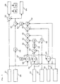
- a generator output signal 31 is put out from a generator output detecting means 16 (Fig. 1) for detecting an output of the generator 5 and is inputted into a subtracter 32 and rate-of-change limiter 33.
- a post-intercept valve steam pressure signal 34 is put out from a post-intercept valve steam pressure detecting means 17 (Fig. 1) for detecting a steam pressure after the intercept valve 14 as a steam turbine inlet steam pressure and is inputted into a function generator 35.
- the function generator 35 that is inputted with a characteristic diagram on the relation between a post-intercept valve steam pressure and a steam turbine output as shown in Fig.
- the rate-of-change limiter 33 is inputted with an output signal from a setting unit 37.
- This setting unit 37 is set with 0% as a rate-of-change set value for the rate-of-change limiter.
- the rate-of-change limiter 33 is inputted with a signal 38.
- This signal 38 is herein defined as a signal that shows a state where the condenser 7 is not in the circulating water reversing. wash operation.
- the rate-of-change limiter 33 adds no rate-of-change limitation onto the generator output signal 31, so that the generator output signal 31 passes through the rate-of-change limiter 33 as it is and is put out into a function generator 39.
- the rate-of-change limiter 33 While the rate-of-change limiter 33 is not inputted with the signal 38, the rate-of-change limiter 33 holds the generator output signal 31 immediately before the rate-of-change limiter 33 is inputted with the signal 38 and puts it out into the function generator 39.
- the function generator 39 that is inputted with a characteristic diagram on the relation between a generator output and a vacuum down amount as shown in Fig. 5, computes the vacuum down amount based on the relation of this characteristic diagram and puts out the vacuum down amount so computed as an output signal into a multiplier 40.
- the rate-of-change limiter 33 and function generator 39 constitute the vacuum down amount computing portion as referred to in the respective claims as appended hereto.
- a condenser reversing valve opening signal 41 is put out from a condenser reversing valve opening detecting means 18 (Fig. 2) for detecting an opening of the condenser reversing valve 23 and is inputted into a rate-of-change limiter 42 and subtracter 43.
- the rate-of-change limiter 42 like the rate-of-change limiter 33, is inputted with an output signal from the setting unit 37 and the signal 38.
- the rate-of-change limiter 42 While the rate-of-change limiter 42 is inputted with the signal 38, the rate-of-change limiter 42 adds no rate-of-change limitation onto the condenser reversing valve opening signal 41, so that the condenser reversing valve opening signal 41 passes through the rate-of-change limiter 42 as it is and is put out into the subtracter 43.
- the rate-of-change limiter 42 While the rate-of-change limiter 42 is not inputted with the signal 38, the rate-of-change limiter 42 holds the condenser reversing valve opening signal 41 immediately before the rate-of-change limiter 42 is inputted with the signal 38 and puts it out into the subtracter 43.
- the subtracter 43 compares the current condenser reversing valve opening signal 41 and the condenser reversing valve opening signal 41 immediately before the rate-of-change limiter 42 is not inputted with the signal 38, that is put out from the rate-of-change limiter 42, and puts out the comparison result as a deviation signal into an absolute value computing portion 44.
- the absolute value computing portion 44 computes an absolute value of the deviation signal inputted from the subtracter 43 and puts out the computed result as an output signal into a function generator 45.
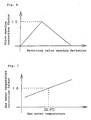
- the function generator 45 that is inputted with a characteristic diagram on the relation between a reversing valve opening deviation and a valve opening correction factor as shown in Fig.
- valve opening correction factor computes the valve opening correction factor based on the relation of this characteristic diagram and puts out the valve opening correction factor so computed as an output signal into the multiplier 40.
- the multiplier 40 multiplies the output signal from the function generator 39 (the vacuum down amount) by the output signal from the function generator 45 (the valve opening correction factor) so as to make a correction of the vacuum down amount and puts out the corrected result into a multiplier 46.
- the rate-of-change limiter 42, subtracter 43, absolute value computing portion 44 and function generator 45 constitute the valve opening correction factor computing portion as referred to in the respective claims as appended hereto.
- a condenser reversing valve inlet sea water temperature signal 47 is put out from a condenser reversing valve inlet sea water temperature detecting means 19 (Fig. 2) for detecting a temperature of the sea water as circulating water in the condenser 7 and is inputted into a function generator 48.
- a condenser reversing valve inlet sea water temperature signal 47 is used in the present embodiment, the signal is not limited thereto but may be any one that shows the temperature of the sea water as circulating water in the condenser 7.
- the function generator 48 that is inputted with a characteristic diagram on the relation between a sea water temperature and a sea water temperature correction factor as shown in Fig.
- the function generator 48 constitutes the sea water temperature correction factor computing portion as referred to in the respective claims as appended hereto.
- a condenser vacuum signal 50 is put out from a condenser vacuum detecting means 20 (Figs. 1 and 2) for detecting a vacuum in the condenser 7 and is inputted into a rate-of-change limiter 51 and higher value selector 52.
- the rate-of-change limiter 51 like the rate-of-change limiter 33 and the rate-of-change limiter 42, is inputted with an output signal from the setting unit 37 and the signal 38.
- the rate-of-change limiter 51 While the rate-of-change limiter 51 is inputted with the signal 38, the rate-of-change limiter 51 adds no rate-of-change limitation onto the condenser vacuum signal 50, so that the condenser vacuum signal 50 passes through the rate-of-change limiter 51 as it is and is put out into the adder 49.
- the rate-of-change limiter 51 selects the condenser vacuum signal 50 as well as holds the condenser vacuum signal 50 immediately before the rate-of-change limiter 51 is not inputted with the signal 38 and puts it out into the adder 49.
- the adder 49 adds the output signal from the rate-of-change limiter 51 and the output signal from the multiplier 46 (the vacuum down amount as corrected by being multiplied by the valve. opening correction factor and sea water temperature correction factor) and puts out the added result into the higher value selector 52.
- the higher value selector 52 selects the higher value signal of the condenser vacuum signal 50 and the output signal from the adder 49 (the condenser vacuum obtained by adding the condenser vacuum signal 50 immediately before the rate-of-change limiter 51 is inputted with the signal 38 and the vacuum down amount multiplied by the valve opening correction factor and sea water temperature correction factor) and puts it out into a function generator 53.
- the function generator 53 that is inputted with a characteristic diagram on the relation between a condenser vacuum and a vacuum correction factor as shown in Fig. 8, computes the vacuum correction factor based on this characteristic diagram and puts out the vacuum correction factor so computed as an output signal into the adder 39.
- the rate-of-change limiter 33, setting unit 37, function generator 39, multiplier 40, rate-of-change limiter 42, subtracter 43, absolute value computing portion 44, function generator 45, multiplier 46, function generator 48, adder 49, rate-of-change limiter 51, higher value selector 52 and function generator 53 constitute the vacuum correction factor computing portion as referred to in the respective claims as appended hereto.
- the multiplier 36 multiplies the output signal from the function generator 35 (the reference steam turbine output) by the output signal from. the function generator 53 (the vacuum correction factor) so as to make a correction of the reference steam turbine output and puts out the corrected result (the steam turbine output) as a steam turbine output signal 54 as well as sends it to the subtracter 32.
- the subtracter 32 subtracts the steam turbine output signal 54 from the generator output signal 31 and puts out a gas turbine output signal 55 (the gas turbine output).
- the gas turbine output signal 55 put out from the subtracter 32 is inputted into a control unit 56 for controlling an angle of a compressor inlet guide vane (IGV) and the control unit 56 controls the angle of the compressor inlet guide vane based on the gas turbine output signal 55.
- the gas turbine output signal 55 put out from the subtracter 32 is inputted into a control unit 57 for controlling an opening of a combustor by-pass valve and the control unit 57 controls the opening of the combustor by-pass valve based on the gas turbine output signal 55.
- the subtracter 32 constitutes the gas turbine output computing portion as referred to in the respective claims as appended hereto.
- the gas turbine output is computed as follows:
- the valve opening correction factor is computed based on the condenser reversing valve opening signal 41 as well as the sea water temperature correction factor is computed based on the condenser reversing valve inlet sea water temperature signal 47.
- the vacuum down amount computed based on the generator output signal 31 immediately before the circulating water reversing wash operation is corrected by being multiplied by the computed valve opening correction factor and sea water temperature correction factor.
- the vacuum down amount so corrected by the valve opening correction factor and sea water temperature correction factor is subtracted from the condenser vacuum signal 50 immediately before the circulating water reversing wash operation to thereby compute the condenser vacuum at the time of the circulating water reversing wash operation and the vacuum correction factor is computed based on the so computed condenser vacuum at the time of the circulating water reversing wash operation.
- the reference steam turbine output computed based on the post-intercept valve steam pressure signal 34 is multiplied by the mentioned vacuum correction factor to thereby compute the steam turbine output signal 54 and then this steam turbine output signal 54 is subtracted from the generator output signal 31 to thereby compute the gas turbine output signal 55.
- the vacuum down amount of the condenser vacuum caused by the circulating water reversing wash operation is computed by the rate-of-change limiter 33 and function generator 39, the condenser vacuum is corrected by the multiplier 40, multiplier 46 and adder 49 based on the computed vacuum down amount and the vacuum correction factor is computed by the function generator 53 based on the corrected condenser vacuum.
- the vacuum down of the condenser vacuum caused by the circulating water reversing wash operation is reflected in the gas turbine output signal 55 that is computed .at the subtracter 32 by subtracting the steam turbine output signal 54 from the generator output signal 31 and the gas turbine output signal 55 can be accurately computed even at the time of the circulating water reversing wash operation.
- the output control of the gas turbine 3, such as adjusting the fuel air amount in the combustor 11, is done based on the gas turbine output signal 55 in which the vacuum down of the condenser is reflected, the operation error of various components and equipments due to the miscomputation of the gas turbine output signal 55 can be prevented.
- the vacuum down amount is computed at the rate-of-change limiter 33 and function generator 39 based on the generator output signal 31 immediately before the circulating water reversing wash operation, the vacuum down amount due to the circulating water reversing wash operation can be appropriately computed.
- valve opening correction factor is computed at the rate-of-change limiter 42, subtracter 43, absolute value computing portion 44 and function generator 45 based on the condenser reversing valve opening signal 41 and the vacuum down amount computed at the rate-of-change limiter 33 and function generator 39 is corrected by being multiplied at the multiplier 40 by the valve opening correction factor, the condenser vacuum that is affected by the opening of the condenser reversing valve 23 can be computed more appropriately.
- the condenser vacuum that is affected by the temperature of the sea water as cooling medium of the condenser 7 can be computed further appropriately.
- the control unit 56 for controlling the angle of the compressor inlet guide vane (IGV) and the control unit 56 controls the angle of the compressor inlet guide vane based on this gas turbine output signal 55, an optimal control of the angle of the compressor inlet guide vane becomes possible and a partial load efficiency of the single-shaft type combined cycle power plant can be enhanced.
- IGV compressor inlet guide vane
- control of the opening of the combustor by-pass valve becomes stable to suppress an occurrence of a misfire and reliability of the gas turbine can be enhanced.
- the construction is made such that the valve opening correction factor is computed at the rate-of-change limiter 42, subtracter 43, absolute value computing portion 44 and function generator 45 based on the condenser reversing valve opening signal 41 and the vacuum down amount computed at the rate-of-change limiter 33 and function generator 39 is corrected by being multiplied at the multiplier 40 by the valve opening correction factor, but the vacuum down amount is not always needed to be corrected by the valve opening correction factor.
- the construction is made such that the sea water temperature correction factor is computed at the function generator 48 based on the condenser reversing valve inlet sea water temperature signal 47 and the vacuum down amount corrected at the multiplier 40 is further corrected at the multiplier 46 by being multiplied by the sea water temperature correction factor, but the vacuum down amount is not always needed to be corrected by the sea water temperature correction factor.
- the vacuum correction factor computing portion comprises the condenser vacuum correcting portion for computing the vacuum down amount in the condenser vacuum caused by the circulating water reversing wash operation while the condenser is in the circulating water reversing wash operation and for correcting the condenser vacuum based on the vacuum down amount and the vacuum correction factor is computed based on the condenser vacuum so corrected at the condenser vacuum correcting portion.
- the vacuum down of the condenser vacuum is reflected in the computation of the gas turbine output at the gas turbine output computing portion.
- the gas turbine output can be accurately computed even at the time of the circulating water reversing wash operation. Also, the output control of the gas turbine (fuel control) is done based on the gas turbine output in which the vacuum down of the condenser vacuum is reflected and the operation error of various components and equipments due to the miscomputation of the gas turbine output can be prevented.
- the vacuum down amount in the condenser vacuum caused by the circulating water reversing wash operation while the condenser is in the circulating water reversing wash operation is computed; and the condenser vacuum is corrected based on the vacuum down amount and the vacuum correction factor is computed based on the condenser vacuum so corrected.
- the vacuum down of the condenser vacuum is reflected in the gas turbine output that is computed by subtracting the steam turbine output from the generator output.
- the gas turbine output can be accurately computed even at the time of the circulating water reversing wash operation.
Landscapes
- Engineering & Computer Science (AREA)
- Chemical & Material Sciences (AREA)
- Combustion & Propulsion (AREA)
- Mechanical Engineering (AREA)
- General Engineering & Computer Science (AREA)
- Engine Equipment That Uses Special Cycles (AREA)
Abstract
Description
Claims (10)
- A gas turbine control apparatus for a single-shaft type combined cycle power plant, said single-shaft type combined cycle power plant comprising a gas turbine (3), steam turbine (6) and generator (5), respective rotational shafts of which are connected together to form a single shaft, and a condenser (7) for condensing exhaust steam of said steam turbine (6), said gas turbine control apparatus comprising:said gas turbine control apparatus being for controlling an output of said gas turbine (3) based on said gas turbine output computed at said gas turbine output computing portion,a vacuum correction factor computing portion for computing a vacuum correction factor based on a condenser vacuum;a steam turbine output computing portion for computing a steam turbine output by multiplying a reference steam turbine output computed based on a steam turbine inlet steam pressure by said vacuum correction factor computed at said vacuum correction factor computing portion; anda gas turbine output computing portion for computing a gas turbine output by subtracting said steam turbine output computed at said steam turbine output computing portion from a generator output,
characterized in that said vacuum correction factor computing portion comprises a condenser vacuum correcting portion for computing a vacuum down amount in said condenser vacuum caused by a circulating water reversing wash operation while said condenser (7) is in the circulating water reversing wash operation and for correcting said condenser vacuum based on said vacuum down amount and said vacuum correction factor is computed based on the condenser vacuum so corrected at said condenser vacuum correcting portion. - A gas turbine control apparatus for a single-shaft type combined cycle power plant as claimed in Claim 1, characterized in that said condenser vacuum correcting portion comprises a vacuum down amount computing portion for computing said vacuum down amount based on the generator output immediately before said circulating water reversing wash operation.
- A gas turbine control apparatus for a single-shaft type combined cycle power plant as claimed in Claim 2, characterized in that said condenser vacuum correcting portion further comprises a valve opening correction factor computing portion for computing a valve opening correction factor based on a condenser reversing valve opening and said vacuum down amount is corrected based on said valve opening correction factor computed at said valve opening correction factor computing portion.
- A gas turbine control apparatus for a single-shaft type combined cycle power plant as claimed in Claim 2 or 3, characterized in that said condenser vacuum correcting portion further comprises a circulating water temperature correction factor computing portion for computing a circulating water temperature correction factor based on a temperature of circulating water supplied into said condenser (7) and said vacuum down amount is corrected based on said circulating water temperature correction factor computed at said circulating water temperature correction factor computing portion.
- A gas turbine control apparatus for a single-shaft type combined cycle power plant as claimed in any one of Claims 1 to 4, characterized in that an angle of a compressor inlet guide vane is controlled based on said gas turbine output computed at said gas turbine output computing portion.
- A gas turbine control apparatus for a single-shaft type combined cycle power plant as claimed in any one of Claims 1 to 5,
characterized in that an opening of a combustor by-pass valve is controlled based on said gas turbine output computed at said gas turbine output computing portion. - A gas turbine output computing method for a single-shaft type combined cycle power plant, said single-shaft type combined cycle power plant comprising a gas turbine (3), steam turbine (6) and generator (5), respective rotational shafts of which are connected together to form a single shaft, and a condenser (7) for condensing exhaust steam of said steam turbine (6), said gas turbine output computing method comprising steps of:characterized in further comprising steps of:computing a vacuum correction factor based on a condenser vacuum;computing a steam turbine output by multiplying a reference steam turbine output computed based on a steam turbine inlet steam pressure by said vacuum correction factor; andcomputing a gas turbine output by subtracting said steam turbine output from a generator output,computing a vacuum down amount in said condenser vacuum caused by a circulating water reversing wash operation while said condenser (7) is in the circulating water reversing wash operation; andcorrecting said condenser vacuum based on said vacuum down amount and computing said vacuum correction factor based on the condenser vacuum so corrected.
- A gas turbine output computing method for a single-shaft type combined cycle power plant as claimed in Claim 7, characterized in comprising a step of computing said vacuum down amount based on the generator output immediately before said circulating water reversing wash operation.
- A gas turbine output computing method for a single-shaft type combined cycle power plant as claimed in Claim 8, characterized in comprising steps of:computing a valve opening correction factor based on a condenser reversing valve opening; andcorrecting said vacuum down amount based on said valve opening correction factor.
- A gas turbine output computing method for a single-shaft type combined cycle power plant as claimed in Claim 8 or 9, characterized in comprising steps of:computing a circulating water temperature correction factor based on a temperature of circulating water supplied into said condenser (7); andcorrecting said vacuum down amount based on said circulating water temperature correction factor.
Applications Claiming Priority (3)
| Application Number | Priority Date | Filing Date | Title |
|---|---|---|---|
| JP36287999 | 1999-12-21 | ||
| JP36287999A JP2001173410A (en) | 1999-12-21 | 1999-12-21 | Gas turbine control device for one axial type combined cycle power generation plant, and gas turbine output calculating method |
| PCT/JP2000/009027 WO2001046567A1 (en) | 1999-12-21 | 2000-12-20 | Gas turbine controller of single-shaft combined cycle power generating plant and gas turbine output calculating method |
Publications (3)
| Publication Number | Publication Date |
|---|---|
| EP1156190A1 true EP1156190A1 (en) | 2001-11-21 |
| EP1156190A4 EP1156190A4 (en) | 2004-03-31 |
| EP1156190B1 EP1156190B1 (en) | 2006-07-12 |
Family
ID=18477966
Family Applications (1)
| Application Number | Title | Priority Date | Filing Date |
|---|---|---|---|
| EP00987651A Expired - Lifetime EP1156190B1 (en) | 1999-12-21 | 2000-12-20 | Gas turbine controller of single-shaft combined cycle power generating plant and gas turbine output calculating method |
Country Status (6)
| Country | Link |
|---|---|
| US (1) | US6477842B1 (en) |
| EP (1) | EP1156190B1 (en) |
| JP (1) | JP2001173410A (en) |
| CA (1) | CA2362827C (en) |
| DE (1) | DE60029311D1 (en) |
| WO (1) | WO2001046567A1 (en) |
Cited By (2)
| Publication number | Priority date | Publication date | Assignee | Title |
|---|---|---|---|---|
| WO2006040185A3 (en) * | 2004-10-14 | 2006-06-29 | Wella Ag | Boiler for producing vapor or hot water |
| WO2015078829A1 (en) * | 2013-11-28 | 2015-06-04 | Siemens Aktiengesellschaft | Thermal power plant |
Families Citing this family (13)
| Publication number | Priority date | Publication date | Assignee | Title |
|---|---|---|---|---|
| US6668537B1 (en) * | 2001-09-26 | 2003-12-30 | Lance G. Hays | Heat recovery system |
| ATE362038T1 (en) * | 2002-07-08 | 2007-06-15 | Siemens Ag | GAS TURBINE SYSTEM WITH AN EXHAUST CHIMNEY |
| JP3716244B2 (en) * | 2002-09-19 | 2005-11-16 | 三菱重工業株式会社 | Operation control apparatus and operation control method for single-shaft combined plant provided with clutch. |
| US7047722B2 (en) * | 2002-10-02 | 2006-05-23 | Claudio Filippone | Small scale hybrid engine (SSHE) utilizing fossil fuels |
| US7055306B2 (en) | 2003-04-30 | 2006-06-06 | Hamilton Sundstrand Corporation | Combined stage single shaft turbofan engine |
| US7574870B2 (en) | 2006-07-20 | 2009-08-18 | Claudio Filippone | Air-conditioning systems and related methods |
| JP4929226B2 (en) | 2008-04-28 | 2012-05-09 | 三菱重工業株式会社 | Gas turbine control device and method for single-shaft combined cycle plant |
| US9016293B2 (en) | 2009-08-21 | 2015-04-28 | Gas Turbine Efficiency Sweden Ab | Staged compressor water wash system |
| US8463445B2 (en) * | 2010-05-28 | 2013-06-11 | General Electric Company | Method and system for safe drum water level determination in a combined cycle operation |
| EP2685055A1 (en) * | 2012-07-12 | 2014-01-15 | Siemens Aktiengesellschaft | Method for supporting a network frequency |
| KR101996281B1 (en) * | 2012-12-31 | 2019-07-04 | 대우조선해양 주식회사 | Generating Capacity Augmentation System For Power Plant Using Combined Cycle |
| CN112815734B (en) * | 2020-12-30 | 2022-09-13 | 大连船舶重工集团有限公司 | Multiple protection system and method for ship vacuum condenser |
| US12215634B1 (en) | 2023-11-21 | 2025-02-04 | General Electric Company | Turbine engine including a steam system |
Family Cites Families (10)
| Publication number | Priority date | Publication date | Assignee | Title |
|---|---|---|---|---|
| US4081956A (en) * | 1976-05-13 | 1978-04-04 | General Electric Company | Combined gas turbine and steam turbine power plant |
| JPS5584805A (en) * | 1978-12-22 | 1980-06-26 | Hitachi Ltd | Method of controlling operation of eight-valve type backwash system for condenser used in thermoelectric or nuclear power plant |
| JPS55112809A (en) * | 1979-02-21 | 1980-09-01 | Hitachi Ltd | Method of running combined-cycle power plant and controller therefor |
| JPS5638503A (en) * | 1979-09-07 | 1981-04-13 | Hitachi Ltd | Erosion preventing apparatus for turbine blade |
| DE3020297A1 (en) * | 1980-05-28 | 1981-12-10 | Kraftwerk Union AG, 4330 Mülheim | PLANT FOR PRODUCING OVERHEATED PROCESS STEAM FROM SALTY RAW WATER |
| JPS6017695A (en) * | 1983-07-08 | 1985-01-29 | Hitachi Ltd | Control device for deaeration steam series of condenser |
| JPS60206907A (en) * | 1984-03-31 | 1985-10-18 | Toshiba Corp | Continuous cleaning device for condenser |
| US5630314A (en) * | 1992-09-10 | 1997-05-20 | Hitachi, Ltd. | Thermal stress relaxation type ceramic coated heat-resistant element |
| JPH08270407A (en) * | 1995-03-30 | 1996-10-15 | Mitsubishi Heavy Ind Ltd | Control of gas turbine in uniaxial composite plant |
| JP4052405B2 (en) * | 1998-05-21 | 2008-02-27 | 三菱重工業株式会社 | Control valve control system when steam turbine cooling steam is introduced |
-
1999
- 1999-12-21 JP JP36287999A patent/JP2001173410A/en not_active Withdrawn
-
2000
- 2000-12-20 CA CA002362827A patent/CA2362827C/en not_active Expired - Fee Related
- 2000-12-20 US US09/890,188 patent/US6477842B1/en not_active Expired - Fee Related
- 2000-12-20 DE DE60029311T patent/DE60029311D1/en not_active Expired - Lifetime
- 2000-12-20 WO PCT/JP2000/009027 patent/WO2001046567A1/en not_active Ceased
- 2000-12-20 EP EP00987651A patent/EP1156190B1/en not_active Expired - Lifetime
Non-Patent Citations (2)
| Title |
|---|
| No further relevant documents disclosed * |
| See also references of WO0146567A1 * |
Cited By (2)
| Publication number | Priority date | Publication date | Assignee | Title |
|---|---|---|---|---|
| WO2006040185A3 (en) * | 2004-10-14 | 2006-06-29 | Wella Ag | Boiler for producing vapor or hot water |
| WO2015078829A1 (en) * | 2013-11-28 | 2015-06-04 | Siemens Aktiengesellschaft | Thermal power plant |
Also Published As
| Publication number | Publication date |
|---|---|
| US6477842B1 (en) | 2002-11-12 |
| DE60029311D1 (en) | 2006-08-24 |
| JP2001173410A (en) | 2001-06-26 |
| CA2362827A1 (en) | 2001-06-28 |
| CA2362827C (en) | 2005-11-01 |
| EP1156190B1 (en) | 2006-07-12 |
| WO2001046567A1 (en) | 2001-06-28 |
| EP1156190A4 (en) | 2004-03-31 |
Similar Documents
| Publication | Publication Date | Title |
|---|---|---|
| EP1156190B1 (en) | Gas turbine controller of single-shaft combined cycle power generating plant and gas turbine output calculating method | |
| EP1205641B1 (en) | Combined cycle gas turbine system | |
| EP1136655B1 (en) | Apparatus and methods of reheating cooling steam in a combined cycle | |
| EP2270317B1 (en) | Apparatus for control of gas turbine in uniaxial combined-cycle plant, and method therefor | |
| JP3431435B2 (en) | Combined power plant and closed air-cooled gas turbine system | |
| JP2006118391A (en) | Control device for extracted air boosting facility in integrated gasification combined cycle plant | |
| JPH0693879A (en) | Combined plant and its operating method | |
| JP4698860B2 (en) | Turbine steam control device | |
| JP3672339B2 (en) | Starting method and starting apparatus for single-shaft combined cycle plant | |
| JP2000303804A (en) | Integrated coal gasification combined cycle power plant and its operation control device. | |
| US6272841B2 (en) | Combined cycle power plant | |
| JP3857350B2 (en) | Control device for combined cycle power plant | |
| JP4607680B2 (en) | Condenser vacuum degree control apparatus and method, and steam turbine plant | |
| JP2685336B2 (en) | Steam-cooled gas turbine combined plant | |
| JP3491967B2 (en) | Gas turbine exhaust gas temperature control device | |
| JPH11148311A (en) | Air extracting device | |
| JP2000297610A (en) | Coal gasification combined plant and operation control method thereof | |
| JPH10331608A (en) | Closed steam-cooled gas turbine combined plant | |
| JPH05340205A (en) | Control device for combined cycle power plant | |
| JP2003148166A (en) | Combined power plant and closed air cooled gas turbine system | |
| JP2949287B2 (en) | Auxiliary steam extraction method for waste heat recovery boiler | |
| EP0978636A1 (en) | Combined cycle power plant | |
| JPH0275731A (en) | Turbine plant | |
| JPS58107805A (en) | Control of turbine for combined cycle power generation | |
| JPS63138102A (en) | Desuperheating control method for turbine bypass |
Legal Events
| Date | Code | Title | Description |
|---|---|---|---|
| PUAI | Public reference made under article 153(3) epc to a published international application that has entered the european phase |
Free format text: ORIGINAL CODE: 0009012 |
|
| 17P | Request for examination filed |
Effective date: 20010718 |
|
| AK | Designated contracting states |
Kind code of ref document: A1 Designated state(s): AT BE CH CY DE DK ES FI FR GB GR IE IT LI LU MC NL PT SE TR |
|
| A4 | Supplementary search report drawn up and despatched |
Effective date: 20040217 |
|
| RBV | Designated contracting states (corrected) |
Designated state(s): CH DE FR GB IT LI |
|
| GRAP | Despatch of communication of intention to grant a patent |
Free format text: ORIGINAL CODE: EPIDOSNIGR1 |
|
| GRAS | Grant fee paid |
Free format text: ORIGINAL CODE: EPIDOSNIGR3 |
|
| GRAA | (expected) grant |
Free format text: ORIGINAL CODE: 0009210 |
|
| AK | Designated contracting states |
Kind code of ref document: B1 Designated state(s): CH DE FR GB IT LI |
|
| PG25 | Lapsed in a contracting state [announced via postgrant information from national office to epo] |
Ref country code: LI Free format text: LAPSE BECAUSE OF FAILURE TO SUBMIT A TRANSLATION OF THE DESCRIPTION OR TO PAY THE FEE WITHIN THE PRESCRIBED TIME-LIMIT Effective date: 20060712 Ref country code: CH Free format text: LAPSE BECAUSE OF FAILURE TO SUBMIT A TRANSLATION OF THE DESCRIPTION OR TO PAY THE FEE WITHIN THE PRESCRIBED TIME-LIMIT Effective date: 20060712 |
|
| REG | Reference to a national code |
Ref country code: GB Ref legal event code: FG4D |
|
| REG | Reference to a national code |
Ref country code: CH Ref legal event code: EP |
|
| REF | Corresponds to: |
Ref document number: 60029311 Country of ref document: DE Date of ref document: 20060824 Kind code of ref document: P |
|
| PG25 | Lapsed in a contracting state [announced via postgrant information from national office to epo] |
Ref country code: DE Free format text: LAPSE BECAUSE OF FAILURE TO SUBMIT A TRANSLATION OF THE DESCRIPTION OR TO PAY THE FEE WITHIN THE PRESCRIBED TIME-LIMIT Effective date: 20061013 |
|
| EN | Fr: translation not filed | ||
| PLBE | No opposition filed within time limit |
Free format text: ORIGINAL CODE: 0009261 |
|
| STAA | Information on the status of an ep patent application or granted ep patent |
Free format text: STATUS: NO OPPOSITION FILED WITHIN TIME LIMIT |
|
| 26N | No opposition filed |
Effective date: 20070413 |
|
| PG25 | Lapsed in a contracting state [announced via postgrant information from national office to epo] |
Ref country code: FR Free format text: LAPSE BECAUSE OF FAILURE TO SUBMIT A TRANSLATION OF THE DESCRIPTION OR TO PAY THE FEE WITHIN THE PRESCRIBED TIME-LIMIT Effective date: 20070511 |
|
| PG25 | Lapsed in a contracting state [announced via postgrant information from national office to epo] |
Ref country code: FR Free format text: LAPSE BECAUSE OF FAILURE TO SUBMIT A TRANSLATION OF THE DESCRIPTION OR TO PAY THE FEE WITHIN THE PRESCRIBED TIME-LIMIT Effective date: 20060712 |
|
| REG | Reference to a national code |
Ref country code: GB Ref legal event code: 732E Free format text: REGISTERED BETWEEN 20151203 AND 20151209 |
|
| PGFP | Annual fee paid to national office [announced via postgrant information from national office to epo] |
Ref country code: GB Payment date: 20151216 Year of fee payment: 16 |
|
| PGFP | Annual fee paid to national office [announced via postgrant information from national office to epo] |
Ref country code: IT Payment date: 20151221 Year of fee payment: 16 |
|
| GBPC | Gb: european patent ceased through non-payment of renewal fee |
Effective date: 20161220 |
|
| PG25 | Lapsed in a contracting state [announced via postgrant information from national office to epo] |
Ref country code: IT Free format text: LAPSE BECAUSE OF NON-PAYMENT OF DUE FEES Effective date: 20161220 |
|
| PG25 | Lapsed in a contracting state [announced via postgrant information from national office to epo] |
Ref country code: GB Free format text: LAPSE BECAUSE OF NON-PAYMENT OF DUE FEES Effective date: 20161220 |