EP1155879A2 - Method for improved determination of the ratios of the wheel radius of a vehicle with each other - Google Patents
Method for improved determination of the ratios of the wheel radius of a vehicle with each other Download PDFInfo
- Publication number
- EP1155879A2 EP1155879A2 EP01109648A EP01109648A EP1155879A2 EP 1155879 A2 EP1155879 A2 EP 1155879A2 EP 01109648 A EP01109648 A EP 01109648A EP 01109648 A EP01109648 A EP 01109648A EP 1155879 A2 EP1155879 A2 EP 1155879A2
- Authority
- EP
- European Patent Office
- Prior art keywords
- vehicle
- wheel
- wheels
- determined
- slip
- Prior art date
- Legal status (The legal status is an assumption and is not a legal conclusion. Google has not performed a legal analysis and makes no representation as to the accuracy of the status listed.)
- Granted
Links
Images


Classifications
-
- B—PERFORMING OPERATIONS; TRANSPORTING
- B60—VEHICLES IN GENERAL
- B60C—VEHICLE TYRES; TYRE INFLATION; TYRE CHANGING; CONNECTING VALVES TO INFLATABLE ELASTIC BODIES IN GENERAL; DEVICES OR ARRANGEMENTS RELATED TO TYRES
- B60C23/00—Devices for measuring, signalling, controlling, or distributing tyre pressure or temperature, specially adapted for mounting on vehicles; Arrangement of tyre inflating devices on vehicles, e.g. of pumps or of tanks; Tyre cooling arrangements
- B60C23/06—Signalling devices actuated by deformation of the tyre, e.g. tyre mounted deformation sensors or indirect determination of tyre deformation based on wheel speed, wheel-centre to ground distance or inclination of wheel axle
- B60C23/061—Signalling devices actuated by deformation of the tyre, e.g. tyre mounted deformation sensors or indirect determination of tyre deformation based on wheel speed, wheel-centre to ground distance or inclination of wheel axle by monitoring wheel speed
Definitions
- the invention relates to a method for improved Determination of the ratio of the radii of the wheels (also Wheel radius ratio) of a vehicle to each other according to the preamble of claim 1.
- Such Radius ratios can, for example Detection of an inadmissible tire pressure used become.
- a method of detecting an inadmissible tire pressure is known from DE 43 27 492 Cl.
- a speed detection device near each wheel arranged from a with the wheel speed rotating, toothed magnet wheel and one immovably attached to the wheel suspension electromagnetic pulse generator exists.
- This Setup can directly determine the speed of the wheel become.
- the wheel speed can be used indirectly of the radius or diameter of the wheel can be determined.
- the invention is therefore based on the object Method for improved determination of the ratio the radii of the wheels of a vehicle to indicate that can also be used without restriction when cornering.
- the invention has the advantage that to compensate for Cornering influences only a vehicle motion signal what is specifically the signal of a is another sensor, which is in current and future Vehicle control systems with vehicle dynamics control is regularly available anyway.
- the cornering influences can then be mathematically compensated become. In practice, this is done through an extension of the calculation and control algorithm in an electronic Control unit implemented. Using one from the Vehicle motion signal obtained yaw rate of the vehicle becomes the influence of cornering from the wheel radius conditions calculated out. The invention is thus can be used practically without additional effort.
- a yaw rate sensor is preferably used as a sensor for determining the vehicle motion signal.
- a steering angle sensor and / or a lateral acceleration sensor can be used, taking from the signals of these sensors the vehicle speed also the Yaw rate of the vehicle in a known manner (DE 198 17 686 A1) can be determined. If several of the previously mentioned sensors are available, so can several of the signals for the mutual plausibility check be used.
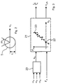
- a yaw rate sensor (7) which emits a vehicle movement signal ( ⁇ ⁇ ) to an electronic control unit (10), is preferably arranged in the area of the center (6) of the vehicle.
- the electronic control unit (10) also receives signals from speed sensors (11, 12, 13, 14) arranged in the area of the wheels (1, 2, 3, 4) and signals from a transverse acceleration sensor (9) as further vehicle movement signals ( ⁇ , a q ) ) and a steering angle sensor (8).
- the speed signals are processed in the electronic control unit (10) and converted into angular speeds ( ⁇ 1 , ⁇ 2 , ⁇ 3 , ⁇ 4 ).
- the relationship of the angular velocities ( ⁇ 1 , ⁇ 2 , ⁇ 3 , ⁇ 4 ), the wheel radii (r 1 , r 2 , r 3 , r 4 ) and the wheel speeds (V 1 , V 2 , V 3 , V 4 ) is shown in Fig. 2 for the wheel (1).
- the angular velocity ( ⁇ 1 , ⁇ 2 , ⁇ 3 , ⁇ 4 ) of a wheel multiplied by the wheel radius (r 1 , r 2 , r 3 , r 4 ) corresponds to the respective wheel speed (V 1 , V 2 , V 3 , V 4 ).
- the signal ( ⁇ ⁇ ) received by the yaw rate sensor (7) is processed by the electronic control unit to a yaw rate ( ⁇ G ), as are the signal ( ⁇ ) received by the steering angle sensor and the signal (a q ) received by the lateral acceleration sensor (9) Consultation of the vehicle speed (V).
- the geometric variables (R, R 1 , R 2 , R 3 , R 4 , L, S) are defined, where (R) indicates the distance between the vehicle center (6) and point (5) , the sizes (R 1 , R 2 , R 3 , R 4 ) indicate the distances of the wheels (1, 2, 3, 4) or the wheel centers to point (5) and the size (S) the track width and Size (L) indicates the wheelbase of the vehicle.
- the driving force signal (F A ) can be supplied to the control unit (10), for example, by an electronic engine control system via a data bus system.
- the drive slip (S A ) is determined from the angular velocities of a front wheel ( ⁇ V ) and a drive wheel ( ⁇ A ), so that an incorrect slip value is determined when cornering.
- the yaw rate ( ⁇ G ) is additionally taken into account by means of the calculation step provided in block (20), which will be explained in more detail below, and thereby the influence of the curve from the drive slip (S A ) is eliminated.
- this is used to determine the drive slip (S A ) of one side of the vehicle (right or left) adjusted for the influence of the curve.
- the calculation step in block (20) and the Kalman filtering in block (21) are therefore carried out twice in the manner of a subroutine, in one case the angular velocities ( ⁇ 1 , ⁇ 3 ) applicable to the left side of the vehicle and the driving force signal (F 3 ) are used as input variables and, accordingly, the variables applicable to the left side of the vehicle (S 3 , r 1 / r 3 , C ⁇ 3 ) are also determined as a result as output variables or intermediate variable.
- the angular velocities ( ⁇ 2 , ⁇ 4 ) applicable to the right side of the vehicle and the driving force signal (F 4 ) are used as input variables, and the values applicable to the right side of the vehicle (S 4 , r 2 / r 4 , C ⁇ 4 ) determined as a result.
- slip values (S 3Korr , S 4Korr ) of the drive wheels can now be determined for the left and right side of the vehicle, which are corrected by the so-called zero slip component.
- the zero slip component corresponds to the zero point (22) of the best-fit line (23) of the Kalman filter (21), ie the slip value at zero driving force.
- the wheel radius ratios of the wheels of an axle are determined as follows using the previously determined results and further geometric vehicle data:
- the slip angle ( ⁇ 1 , ⁇ 2 , ⁇ 3 , ⁇ 4 ), as shown in FIG. 4, is taken into account to determine the drive slip (S A ).
- the slip angle of a wheel indicates the angular amount by which the actual movement of a wheel deviates from the theoretically given direction with slip-free behavior, ie the slip angle is a measure of the lateral slip of a wheel. Taking the slip angle ( ⁇ 1 , ⁇ 2 , ⁇ 3 , ⁇ 4 ) into account, the drive slip (S A ) can be determined according to the following relationship:
- Equation [7] preferably comes in block (20) alternative to equation [2] for use, i.e. she is also used once for the left side of the vehicle and one more time for the right vehicle side executed.
- the wheel radius ratios determined in this way (r 1 / r 2 , r 1 / r 3 , r 2 / r 4 , r 3 / r 4 ) are continuously monitored by means of a monitoring program provided in the control unit (10).
- a monitoring program provided in the control unit (10).
- an impermissible tire pressure is then recognized and displayed as a warning signal via an indicator lamp (not shown in FIG. 1) arranged in the driver's field of vision.
- the characteristic change is preferably detected when a predetermined threshold value is exceeded, as will be explained using the following example.
- the right rear wheel (4) assumes an inadmissibly low tire pressure, somewhat as a result of tire damage.
- the radius (r 4 ) decreases without significant changes to the radii (r 1 , r 2 , r 3 ).
- the control unit (10) recognizes this by the fact that both the wheel radius ratio (r 2 / r 4 ) on the right-hand side of the vehicle and the wheel radius ratio (r 3 / r 4 ) on the rear axle increase and the threshold value mentioned above is exceeded in each case.
- the wheel radius ratios (r 1 / r 2 , r 1 / r 3 ) essentially retain their values.
Abstract
Description
Die Erfindung betrifft ein Verfahren zur verbesserten Bestimmung des Verhältnisses der Radien der Räder (auch Radradienverhältnis genannt) eines Fahrzeuges zueinander gemäß dem Oberbegriff des Patentanspruchs 1. Derartige Radradienverhältnisse können beispielsweise zur Erkennung eines unzulässigen Reifendrucks verwendet werden.The invention relates to a method for improved Determination of the ratio of the radii of the wheels (also Wheel radius ratio) of a vehicle to each other according to the preamble of claim 1. Such Radius ratios can, for example Detection of an inadmissible tire pressure used become.
Ein Verfahren zur Erkennung eines unzulässigen Reifendrucks ist aus der DE 43 27 492 Cl bekannt.A method of detecting an inadmissible tire pressure is known from DE 43 27 492 Cl.
Bei Fahrzeugen mit einem Antiblockiersystem ist üblicherweise in der Nähe jedes Rades eine Drehzahlerfassungseinrichtung angeordnet, die aus einem mit der Raddrehzahl drehenden, mit Zähnen versehenen Polrad und einem unbeweglich an der Radaufhängung befestigten elektromagnetischen Impulsgeber besteht. Mittels dieser Einrichtung kann die Drehzahl des Rades direkt bestimmt werden. Die Radgeschwindigkeit kann indirekt unter Verwendung des Radradius oder -durchmessers bestimmt werden. In vehicles with an anti-lock braking system is common a speed detection device near each wheel arranged from a with the wheel speed rotating, toothed magnet wheel and one immovably attached to the wheel suspension electromagnetic pulse generator exists. By means of this Setup can directly determine the speed of the wheel become. The wheel speed can be used indirectly of the radius or diameter of the wheel can be determined.
Bei der Auswertung der Drehzahlsignale im Rahmen von bestimmten Regelungs- oder Warnfunktionen, bei denen die Drehzahlsignale miteinander verglichen werden, wie z. B. bei einer Schlupfregelung oder einer Reifendruckwarnung, tritt bei Kurvenfahrt eine Differenz zwischen den Drehzahlsignalen auf, welche nicht zu einer Auslösung der Regelungs- oder Warnfunktion führen soll. Die Drehzahldifferenz infolge der Kurvenfahrt ist jedoch nicht ohne weiteres von einer durch Radschlupf oder Reifendruckänderung hervorgerufenen Drehzahldifferenz zu unterscheiden. Bei dem bekannten Verfahren wird dieses Problem dadurch umgangen, daß die Kurvenfahrt, bzw. zumindest ein oberhalb eines vorgegebenen Kurvenfahrt-Grenzwertes liegender Grad an Kurvenfahrt, aus dem Verfahren ausgeklammert wird.When evaluating the speed signals as part of certain control or warning functions where the speed signals are compared, such as e.g. B. in a slip control or a tire pressure warning, a difference occurs when cornering the speed signals, which do not trigger the control or warning function. The However, speed difference due to cornering is not easily from one by wheel slip or Tire pressure change caused speed difference to distinguish. In the known method, this is Worked around the problem that the cornering, or at least one above a predetermined cornering limit lying degree of cornering, from the procedure is excluded.
Der Erfindung liegt daher die Aufgabe zugrunde, ein Verfahren zur verbesserten Bestimmung des Verhältnisses der Radien der Räder eines Fahrzeuges anzugeben, das auch bei Kurvenfahrt ohne Einschränkung einsetzbar ist.The invention is therefore based on the object Method for improved determination of the ratio the radii of the wheels of a vehicle to indicate that can also be used without restriction when cornering.
Diese Aufgabe wird durch die in dem Patentanspruch 1 angegebene Erfindung gelöst. Weiterbildungen und vorteilhafte Ausgestaltungen der Erfindung sind in den Unteransprüchen angegeben.This object is achieved by the in claim 1 specified invention solved. Training and advantageous Embodiments of the invention are in the subclaims specified.
Die Erfindung hat den Vorteil, daß zur Kompensation der Kurvenfahrteinflüsse lediglich ein Fahrzeugbewegungssignal erforderlich ist, was konkret das Signal eines weiteren Sensors ist, welcher in derzeitigen und zukünftigen Fahrzeugregelungssystemen mit Fahrdynamikregelung ohnehin regelmäßig vorhanden ist. Die Kurvenfahrteinflüsse können dann rein rechnerisch kompensiert werden. Dies wird in der Praxis durch eine Erweiterung des Rechen- und Steueralgorithmus in einem elektronischen Steuergerät realisiert. Mittels einer aus dem Fahrzeugbewegungssignal gewonnenen Gierrate des Fahrzeuges wird der Kurvenfahrteinfluß aus den Radradienverhältnissen herausgerechnet. Die Erfindung ist somit praktisch ohne Mehraufwand einsetzbar.The invention has the advantage that to compensate for Cornering influences only a vehicle motion signal what is specifically the signal of a is another sensor, which is in current and future Vehicle control systems with vehicle dynamics control is regularly available anyway. The cornering influences can then be mathematically compensated become. In practice, this is done through an extension of the calculation and control algorithm in an electronic Control unit implemented. Using one from the Vehicle motion signal obtained yaw rate of the vehicle becomes the influence of cornering from the wheel radius conditions calculated out. The invention is thus can be used practically without additional effort.
Als Sensor zur Ermittlung des Fahrzeugbewegungssignals wird vorzugsweise ein Gierratensensor verwendet. In einer vorteilhaften Ausgestaltung der Erfindung kann alternativ oder zusätzlich auch ein Lenkwinkelsensor und/oder ein Querbeschleunigungssensor eingesetzt werden, wobei aus den Signalen dieser Sensoren unter Hinzuziehung der Fahrzeuggeschwindigkeit ebenfalls die Gierrate des Fahrzeugs in bekannter Weise (DE 198 17 686 A1) ermittelt werden kann. Wenn mehrere der zuvor genannten Sensoren zur Verfügung stehen, so können auch mehrere der Signale zur gegenseitigen Plausibilitätsprüfung verwendet werden.As a sensor for determining the vehicle motion signal a yaw rate sensor is preferably used. In a advantageous embodiment of the invention can alternatively or additionally a steering angle sensor and / or a lateral acceleration sensor can be used, taking from the signals of these sensors the vehicle speed also the Yaw rate of the vehicle in a known manner (DE 198 17 686 A1) can be determined. If several of the previously mentioned sensors are available, so can several of the signals for the mutual plausibility check be used.
Die Erfindung wird im folgenden unter Verwendung von Zeichnungen näher erläutert.The invention is hereinafter described using Drawings explained in more detail.
Es zeigen
- Fig. 1
- ein schematisches Modell eines vierrädrigen Fahrzeuges in Draufsicht und
- Fig. 2
- ein Rad des Fahrzeugs gemäß Fig. 1 und
- Fig. 3
- eine bevorzugte Ausführungsform der Erfindung als Blockdiagramm und
- Fig. 4
- das Fahrzeug gemäß Fig. 1 in einer erweiterten Darstellung.
- Fig. 1
- a schematic model of a four-wheel vehicle in plan view and
- Fig. 2
- a wheel of the vehicle according to FIG. 1 and
- Fig. 3
- a preferred embodiment of the invention as a block diagram and
- Fig. 4
- the vehicle of FIG. 1 in an expanded representation.
In den Figuren werden gleiche Bezugszeichen für einander entsprechende Teile und Signale verwendet.In the figures, the same reference numerals are used for one another appropriate parts and signals used.
In der Fig. 1 sind die für die Erläuterung der Erfindung erforderlichen Teile eines Fahrzeugs sowie die zugehörigen physikalischen Größen dargestellt. Das Fahrzeug weist vier Räder (1, 2, 3, 4) auf, die sich mit Geschwindigkeiten (V1, V2, V3, V4) relativ zu einem Punkt (5) bewegen. In der Darstellung gemäß Fig. 1 befindet sich das Fahrzeug in einer Rechtskurve. Der Mittelpunkt des Fahrzeugs (6) bewegt sich mit einer Geschwindigkeit (V) ebenfalls relativ zu dem Punkt (5). Vorzugsweise im Bereich des Mittelpunkts (6) des Fahrzeugs ist ein Gierratensensor (7) angeordnet, der ein Fahrzeugbewegungssignal (ψ ˙) an ein elektronisches Steuergerät (10) abgibt. Das elektronische Steuergerät (10) empfängt außerdem Signale von im Bereich der Räder (1, 2, 3, 4) angeordneten Drehzahlsensoren (11, 12, 13, 14) sowie als weitere Fahrzeugbewegungssignale (δ, aq) Signale von einem Querbeschleunigungssensor (9) und einem Lenkwinkelsensor (8).1 shows the parts of a vehicle required for the explanation of the invention and the associated physical quantities. The vehicle has four wheels (1, 2, 3, 4) that move at speeds (V 1 , V 2 , V 3 , V 4 ) relative to a point (5). 1, the vehicle is in a right turn. The center of the vehicle (6) also moves at a speed (V) relative to the point (5). A yaw rate sensor (7), which emits a vehicle movement signal (ψ ˙) to an electronic control unit (10), is preferably arranged in the area of the center (6) of the vehicle. The electronic control unit (10) also receives signals from speed sensors (11, 12, 13, 14) arranged in the area of the wheels (1, 2, 3, 4) and signals from a transverse acceleration sensor (9) as further vehicle movement signals (δ, a q ) ) and a steering angle sensor (8).
Die Drehzahlsignale werden in dem elektronischen Steuergerät
(10) aufbereitet und in Winkelgeschwindigkeiten
(ω1, ω2, ω3, ω4) umgerechnet. Der Zusammenhang der Winkelgeschwindigkeiten
(ω1, ω2, ω3, ω4), der Radradien
(r1, r2, r3, r4) und der Radgeschwindigkeiten (V1, V2,
V3, V4) ist in der Fig. 2 für das Rad (1) dargestellt.
Bei schlupffreier Bewegung entspricht die Winkelgeschwindigkeit
(ω1, ω2, ω3, ω4) eines Rades multipliziert
mit dem Radradius (r1, r2, r3, r4) der jeweiligen Radgeschwindigkeit
(V1, V2, V3, V4) . Bezüglich des Rades (1)
lautet somit der Zusammenhang konkret:
Das von dem Gierratensensor (7) empfangene Signal (ψ ˙) verarbeitet das elektronische Steuergerät zu einer Gierrate (ωG), ebenso das von dem Lenkwinkelsensor empfangene Signal (δ) und das von dem Querbeschleunigungssensor (9) empfangene Signal (aq) unter Hinzuziehung der Fahrzeuggeschwindigkeit (V).The signal (ψ ˙) received by the yaw rate sensor (7) is processed by the electronic control unit to a yaw rate (ω G ), as are the signal (δ) received by the steering angle sensor and the signal (a q ) received by the lateral acceleration sensor (9) Consultation of the vehicle speed (V).
Des weiteren seien anhand der Fig. 1 die geometrischen Größen (R, R1, R2, R3, R4, L, S) definiert, wobei (R) den Abstand des Fahrzeugmittelpunkts (6) von dem Punkt (5) angibt, die Größen (R1, R2, R3, R4) die Abstände der Räder (1, 2, 3, 4) bzw. der Radmittelpunkte zu dem Punkt (5) angeben und die Größe (S) die Spurweite und die Größe (L) den Radstand des Fahrzeugs angibt.1, the geometric variables (R, R 1 , R 2 , R 3 , R 4 , L, S) are defined, where (R) indicates the distance between the vehicle center (6) and point (5) , the sizes (R 1 , R 2 , R 3 , R 4 ) indicate the distances of the wheels (1, 2, 3, 4) or the wheel centers to point (5) and the size (S) the track width and Size (L) indicates the wheelbase of the vehicle.
In der Fig. 3 ist schematisch dargestellt, wie anhand
des Antriebsschlupfs (SA) eines Antriebsrades (3 oder
4) bezogen auf ein nicht angetriebenes Rad (1 oder 2)
und eines Antriebskraftsignals (FA) mittels eines dem
Fachmann im einzelnen bekannten Kalman-Filters (21) ein
Radradienverhältnis (rV/rA) zwischen dem jeweils verwendeten
Vorderrad (1, 2) und dem jeweils verwendeten
Hinterrad (3, 4) bestimmt wird. Des weiteren wird mittels
des Kalman-Filters (21) eine Reifensteifigkeit
(CλA) bestimmt, welche eine Aussage über das Reibverhalten
des Reifens auf dem jeweiligen Untergrund erlaubt.
Die Verwendung eines Kalman-Filters für derartige
Zwecke ist beispielsweise im einzelnen in folgenden
Veröffentlichungen näher erläutert:
Das Antriebskraftsignal (FA) kann beispielsweise von einer elektronischen Motorsteuerung über ein Datenbussystem dem Steuergerät (10) zugeführt werden.The driving force signal (F A ) can be supplied to the control unit (10), for example, by an electronic engine control system via a data bus system.
Bei bekannten Verfahren wird der Antriebsschlupf (SA) aus den Winkelgeschwindigkeiten eines Vorderrades (ωV) und eines Antriebsrades (ωA) bestimmt, so daß bei Kurvenfahrt ein unkorrekter Schlupfwert ermittelt wird. Bei der vorliegenden Erfindung wird nun mittels des in dem Block (20) vorgesehenen Rechenschritts, der im folgenden noch näher erläutert wird, zusätzlich die Gierrate (ωG) berücksichtigt und hierdurch der Kurveneinfluß aus dem Antriebsschlupf (SA) eliminiert.In known methods, the drive slip (S A ) is determined from the angular velocities of a front wheel (ω V ) and a drive wheel (ω A ), so that an incorrect slip value is determined when cornering. In the present invention, the yaw rate (ω G ) is additionally taken into account by means of the calculation step provided in block (20), which will be explained in more detail below, and thereby the influence of the curve from the drive slip (S A ) is eliminated.
In einer bevorzugten Ausführungsform der Erfindung wird
der Antriebsschlupf (SA) in dem Block (20) gemäß folgender
Gleichung bestimmt:
Hiermit wird, wie schon erwähnt, der um den Kurveneinfluß bereinigte Antriebsschlupf (SA) einer Fahrzeugseite (rechts oder links) bestimmt. Der Rechenschritt gemäß Block (20) wie auch die Kalman-Filterung gemäß Block (21) wird daher zweimal nach Art eines Unterprogramms ausgeführt, wobei im einen Fall die für die linke Fahrzeugseite geltenden Winkelgeschwindigkeiten (ω1, ω3) und das Antriebskraftsignal (F3) als Eingangsgrößen verwendet werden und dementsprechend als Ausgangsgrößen bzw. Zwischengröße auch die für die linke Fahrzeugseite geltenden Größen (S3, r1/r3, Cλ3) als Ergebnis ermittelt werden. Im anderen Fall werden die für die rechte Fahrzeugseite geltenden Winkelgeschwindigkeiten (ω2, ω4) und das Antriebskraftsignal (F4) als Eingangsgrößen verwendet, und es werden die für die rechte Fahrzeugseite geltenden Größen (S4, r2/r4, Cλ4) als Ergebnis ermittelt. As already mentioned, this is used to determine the drive slip (S A ) of one side of the vehicle (right or left) adjusted for the influence of the curve. The calculation step in block (20) and the Kalman filtering in block (21) are therefore carried out twice in the manner of a subroutine, in one case the angular velocities (ω 1 , ω 3 ) applicable to the left side of the vehicle and the driving force signal (F 3 ) are used as input variables and, accordingly, the variables applicable to the left side of the vehicle (S 3 , r 1 / r 3 , C λ3 ) are also determined as a result as output variables or intermediate variable. In the other case, the angular velocities (ω 2 , ω 4 ) applicable to the right side of the vehicle and the driving force signal (F 4 ) are used as input variables, and the values applicable to the right side of the vehicle (S 4 , r 2 / r 4 , C λ4 ) determined as a result.
Aus diesen Ergebnissen können nun für die linke und die
rechte Fahrzeugseite Schlupfwerte (S3Korr, S4Korr) der Antriebsräder
ermittelt werden, die um den sogenannten
Nullschlupfanteil korrigiert sind. Der Nullschlupfanteil
entspricht der Nullstelle (22) der Ausgleichsgeraden
(23) des Kalman-Filters (21), d.h. der Schlupfwert
bei der Antriebskraft Null. Der Nullschlupfanteil ist
definitionsgemäß außerdem identisch mit dem Radradienverhältnis
derselben Fahrzeugseite, so daß die korrigierten
Schlupfwerte (S3Korr, S4Korr) wie folgt ermittelt
werden können:
In einer bevorzugten Ausgestaltung der Erfindung werden
die Radradienverhältnisse der Räder einer Achse unter
Verwendung der zuvor bestimmten Ergebnisse und weiterer
geometrischer Fahrzeugdaten wie folgt bestimmt:


In einer weiteren vorteilhaften Ausgestaltung der Erfindung
werden zur Bestimmung des Antriebsschlupfs (SA)
neben den schon erwähnten Größen auch die Schräglaufwinkel
(α1, α2, α3, α4), wie in der Fig. 4 dargestellt,
berücksichtigt. Hierdurch läßt sich ein hinsichtlich
der Genauigkeit noch weiter verbessertes Ergebnis bei
der Bestimmung der Radradienverhältnisse erzielen. Der
Schräglaufwinkel eines Rades gibt an, um welchen Winkelbetrag
die wirkliche Bewegung eines Rades von der
bei schlupffreiem Verhalten theoretisch vorliegenden
Richtung abweicht, d. h. der Schräglaufwinkel ist ein
Maß für den seitlichen Schlupf eines Rades. Unter Einbeziehung
der Schräglaufwinkel (α1, α2, α3, α4) kann der
Antriebsschlupf (SA) gemäß folgender Beziehung bestimmt
werden:
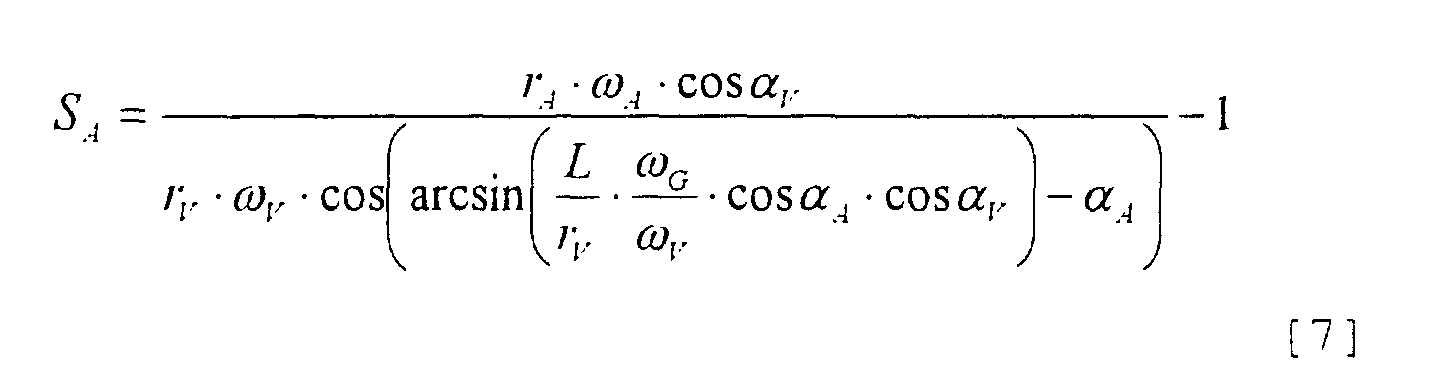
Die Gleichung [7] kommt vorzugsweise in dem Block (20) alternativ zu der Gleichung [2] zur Anwendung, d.h. sie wird ebenfalls nach Art eines Unterprogramms einmal für die linke Fahrzeugseite und ein weiteres Mal für die rechte Fahrzeugseite ausgeführt.Equation [7] preferably comes in block (20) alternative to equation [2] for use, i.e. she is also used once for the left side of the vehicle and one more time for the right vehicle side executed.
Mittels eines in dem Steuergerät (10) vorgesehenen Überwachungsprogramms werden nun fortlaufend die so ermittelten Radradienverhältnisse (r1/r2, r1/r3, r2/r4, r3/r4) überwacht. Bei einer charakteristischen Änderung des Verhältnisses eines Rades zu den anderen Rädern wird dann ein unzulässiger Reifendruck erkannt und über eine in der Fig. 1 nicht dargestellte, im Blickfeld des Fahrers angeordnete Anzeigelampe als Warnsignal angezeigt. Die Erkennung der charakteristischen Änderung erfolgt vorzugsweise dann, wenn ein vorbestimmter Schwellenwert überschritten wird, wie anhand des folgenden Beispiels erläutert werden soll.The wheel radius ratios determined in this way (r 1 / r 2 , r 1 / r 3 , r 2 / r 4 , r 3 / r 4 ) are continuously monitored by means of a monitoring program provided in the control unit (10). In the event of a characteristic change in the ratio of one wheel to the other wheels, an impermissible tire pressure is then recognized and displayed as a warning signal via an indicator lamp (not shown in FIG. 1) arranged in the driver's field of vision. The characteristic change is preferably detected when a predetermined threshold value is exceeded, as will be explained using the following example.
Es sei angenommen, daß das rechte Hinterrad (4) einen unzulässig niedrigen Reifendruck annimmt, etwas infolge eines Reifenschadens. In diesem Fall verringert sich der Radius (r4), ohne daß sich nennenswerte Veränderungen an den Radien (r1, r2, r3) ergeben. Dies erkennt das Steuergerät (10) daran, daß sich sowohl das Radradienverhältnis (r2/r4) der rechten Fahrzeugseite als auch das Radradienverhältnis (r3/r4) der Hinterachse erhöht und hierbei jeweils der zuvor erwähnte Schwellenwert überschritten wird. Die Radradienverhältnisse (r1/r2, r1/r3) behalten dabei im wesentlichen ihre Werte bei.It is assumed that the right rear wheel (4) assumes an inadmissibly low tire pressure, somewhat as a result of tire damage. In this case the radius (r 4 ) decreases without significant changes to the radii (r 1 , r 2 , r 3 ). The control unit (10) recognizes this by the fact that both the wheel radius ratio (r 2 / r 4 ) on the right-hand side of the vehicle and the wheel radius ratio (r 3 / r 4 ) on the rear axle increase and the threshold value mentioned above is exceeded in each case. The wheel radius ratios (r 1 / r 2 , r 1 / r 3 ) essentially retain their values.
Claims (5)
Applications Claiming Priority (2)
| Application Number | Priority Date | Filing Date | Title |
|---|---|---|---|
| DE10024178 | 2000-05-17 | ||
| DE10024178A DE10024178A1 (en) | 2000-05-17 | 2000-05-17 | Method for improved determination of the ratio of the radii of the wheels of a vehicle to one another |
Publications (3)
| Publication Number | Publication Date |
|---|---|
| EP1155879A2 true EP1155879A2 (en) | 2001-11-21 |
| EP1155879A3 EP1155879A3 (en) | 2003-12-10 |
| EP1155879B1 EP1155879B1 (en) | 2007-02-14 |
Family
ID=7642399
Family Applications (1)
| Application Number | Title | Priority Date | Filing Date |
|---|---|---|---|
| EP01109648A Expired - Lifetime EP1155879B1 (en) | 2000-05-17 | 2001-04-19 | Method for improved determination of the ratios of the wheel radius of a vehicle with each other |
Country Status (3)
| Country | Link |
|---|---|
| US (1) | US6644105B2 (en) |
| EP (1) | EP1155879B1 (en) |
| DE (2) | DE10024178A1 (en) |
Cited By (10)
| Publication number | Priority date | Publication date | Assignee | Title |
|---|---|---|---|---|
| EP1826530A1 (en) * | 2006-02-24 | 2007-08-29 | Volkswagen Aktiengesellschaft | Method and device for determining the circumference of a wheel |
| WO2008017527A1 (en) * | 2006-08-10 | 2008-02-14 | Continental Automotive Gmbh | Method and apparatus for operating a vehicle |
| EP1315646B1 (en) * | 2001-09-07 | 2010-08-18 | Kelsey-Hayes Company | Advanced wheel slip detection using suspension system information |
| DE102012018000B3 (en) * | 2012-09-12 | 2013-11-07 | Volkswagen Aktiengesellschaft | Method for determining relative wheel rolling circumference ratio of rear wheels of motor car, involves selecting relative rear wheel ratio as circumference ratio of rear wheels if rear and/or front wheel ratio comprises maximum value |
| CN103674559A (en) * | 2012-08-31 | 2014-03-26 | 弥荣(成都)实业有限公司 | Automobile brake inspection bench capable of preventing wheels from deviating from simulated road surface |
| DE102012023021A1 (en) * | 2012-11-26 | 2014-05-28 | GM Global Technology Operations LLC (n. d. Ges. d. Staates Delaware) | Method of determining tire tread value within driving operation of motor vehicle, involves repeatedly detecting steering angle of motor vehicle, where each steering angle is assigned to travel curve parameter |
| DE102013014198A1 (en) * | 2013-08-23 | 2015-02-26 | Wabco Gmbh | Method and device for determining a faulty parameterization of Radumfängen |
| EP3483582A1 (en) * | 2017-11-06 | 2019-05-15 | Linde Material Handling GmbH | Method and device for determining the wear of a tyre in an industrial truck |
| CN109910527A (en) * | 2019-03-26 | 2019-06-21 | 武汉理工大学 | A kind of tire pressure of automobile tire determines method and apparatus |
| CN114423663A (en) * | 2019-09-27 | 2022-04-29 | 蒂森克虏伯普利斯坦股份公司 | Method for iteratively determining the radius of a motor vehicle wheel |
Families Citing this family (10)
| Publication number | Priority date | Publication date | Assignee | Title |
|---|---|---|---|---|
| SE0002213D0 (en) * | 2000-04-12 | 2000-06-13 | Nira Automotive Ab | Tire pressure computation system |
| US6970774B2 (en) * | 2002-05-31 | 2005-11-29 | Quantum Engineering, Inc. | Method and system for compensating for wheel wear on a train |
| US7392696B1 (en) | 2007-04-10 | 2008-07-01 | Toyota Motor Engineering & Manufacturing North America, Inc. | Sensorless tire pressure estimating method for vehicle with ABS brake control |
| JP5550891B2 (en) * | 2009-12-11 | 2014-07-16 | Ntn株式会社 | Control device and control method for electric vehicle |
| DE102010006178B4 (en) * | 2010-01-29 | 2019-02-21 | Continental Automotive Gmbh | Method for monitoring a tire pressure and tire pressure monitoring device |
| DE102013004900A1 (en) * | 2013-03-21 | 2014-09-25 | Valeo Schalter Und Sensoren Gmbh | Method for determining a current circumference of a wheel of a motor vehicle, driver assistance device and motor vehicle |
| DE102016010750B4 (en) * | 2016-09-06 | 2018-07-12 | Nira Dynamics Ab | Estimate absolute wheel radius and estimate a vertical compression value |
| DE102016223902B4 (en) | 2016-12-01 | 2019-12-19 | Audi Ag | Method and system for determining the wheel circumference and track width of a vehicle |
| CN110849387B (en) * | 2018-08-20 | 2024-01-12 | 北京京东尚科信息技术有限公司 | Sensor parameter calibration method and device |
| FR3095510B1 (en) * | 2019-04-23 | 2021-03-19 | Continental Automotive | Method for estimating an index representative of the frictional behavior of a vehicle on a road |
Citations (2)
| Publication number | Priority date | Publication date | Assignee | Title |
|---|---|---|---|---|
| DE4327492C1 (en) | 1993-08-16 | 1995-02-16 | Daimler Benz Ag | Tire pressure warning procedure |
| DE19817686A1 (en) | 1998-04-21 | 1999-10-28 | Wabco Gmbh | Method for determining a comparison variable |
Family Cites Families (4)
| Publication number | Priority date | Publication date | Assignee | Title |
|---|---|---|---|---|
| AU663018B2 (en) * | 1992-12-24 | 1995-09-21 | Sumitomo Rubber Industries, Ltd. | Method and device for detecting pneumatic abnormalities of tyre |
| JP3509330B2 (en) * | 1995-10-11 | 2004-03-22 | 本田技研工業株式会社 | Vehicle wheel pressure reduction judgment device |
| DE19807880A1 (en) * | 1998-02-25 | 1999-09-09 | Daimler Chrysler Ag | Method and device for monitoring the tire air pressure of wheels of a motor vehicle |
| JP3649036B2 (en) * | 1999-03-26 | 2005-05-18 | 日産自動車株式会社 | Yaw rate estimation device |
-
2000
- 2000-05-17 DE DE10024178A patent/DE10024178A1/en not_active Withdrawn
-
2001
- 2001-04-19 DE DE50112020T patent/DE50112020D1/en not_active Expired - Lifetime
- 2001-04-19 EP EP01109648A patent/EP1155879B1/en not_active Expired - Lifetime
- 2001-04-27 US US09/844,039 patent/US6644105B2/en not_active Expired - Lifetime
Patent Citations (2)
| Publication number | Priority date | Publication date | Assignee | Title |
|---|---|---|---|---|
| DE4327492C1 (en) | 1993-08-16 | 1995-02-16 | Daimler Benz Ag | Tire pressure warning procedure |
| DE19817686A1 (en) | 1998-04-21 | 1999-10-28 | Wabco Gmbh | Method for determining a comparison variable |
Cited By (13)
| Publication number | Priority date | Publication date | Assignee | Title |
|---|---|---|---|---|
| EP1315646B1 (en) * | 2001-09-07 | 2010-08-18 | Kelsey-Hayes Company | Advanced wheel slip detection using suspension system information |
| EP1826530A1 (en) * | 2006-02-24 | 2007-08-29 | Volkswagen Aktiengesellschaft | Method and device for determining the circumference of a wheel |
| WO2008017527A1 (en) * | 2006-08-10 | 2008-02-14 | Continental Automotive Gmbh | Method and apparatus for operating a vehicle |
| US8280587B2 (en) | 2006-08-10 | 2012-10-02 | Continental Automotive Gmbh | Method and apparatus for operating a vehicle |
| CN103674559B (en) * | 2012-08-31 | 2016-02-03 | 弥荣(成都)实业有限公司 | Can prevent wheel from departing from the Vehicles Brake Test Bench of simulated roadway |
| CN103674559A (en) * | 2012-08-31 | 2014-03-26 | 弥荣(成都)实业有限公司 | Automobile brake inspection bench capable of preventing wheels from deviating from simulated road surface |
| DE102012018000B3 (en) * | 2012-09-12 | 2013-11-07 | Volkswagen Aktiengesellschaft | Method for determining relative wheel rolling circumference ratio of rear wheels of motor car, involves selecting relative rear wheel ratio as circumference ratio of rear wheels if rear and/or front wheel ratio comprises maximum value |
| DE102012023021A1 (en) * | 2012-11-26 | 2014-05-28 | GM Global Technology Operations LLC (n. d. Ges. d. Staates Delaware) | Method of determining tire tread value within driving operation of motor vehicle, involves repeatedly detecting steering angle of motor vehicle, where each steering angle is assigned to travel curve parameter |
| DE102013014198A1 (en) * | 2013-08-23 | 2015-02-26 | Wabco Gmbh | Method and device for determining a faulty parameterization of Radumfängen |
| EP3483582A1 (en) * | 2017-11-06 | 2019-05-15 | Linde Material Handling GmbH | Method and device for determining the wear of a tyre in an industrial truck |
| CN109910527A (en) * | 2019-03-26 | 2019-06-21 | 武汉理工大学 | A kind of tire pressure of automobile tire determines method and apparatus |
| CN109910527B (en) * | 2019-03-26 | 2021-02-19 | 武汉理工大学 | Method and device for determining tire pressure of automobile tire |
| CN114423663A (en) * | 2019-09-27 | 2022-04-29 | 蒂森克虏伯普利斯坦股份公司 | Method for iteratively determining the radius of a motor vehicle wheel |
Also Published As
| Publication number | Publication date |
|---|---|
| DE10024178A1 (en) | 2001-12-06 |
| US20010054310A1 (en) | 2001-12-27 |
| US6644105B2 (en) | 2003-11-11 |
| EP1155879B1 (en) | 2007-02-14 |
| EP1155879A3 (en) | 2003-12-10 |
| DE50112020D1 (en) | 2007-03-29 |
Similar Documents
| Publication | Publication Date | Title |
|---|---|---|
| EP1155879B1 (en) | Method for improved determination of the ratios of the wheel radius of a vehicle with each other | |
| EP1692026B1 (en) | Method and arrangement for monitoring a measuring device located in a wheeled vehicle | |
| EP2170631B1 (en) | Method and device for monitoring the state of tyres | |
| DE112017005121B4 (en) | Apparatus with motor vehicle moving condition evaluation device | |
| EP2111557B1 (en) | Method and device for determining the speed of a vehicle | |
| DE102013219662B3 (en) | Method, control unit and system for determining a tread depth of a profile of at least one tire | |
| EP1118519B1 (en) | Method for detection of a faulty installation of a control unit in a motor vehicle | |
| DE4141931C2 (en) | Device for generating a signal for controlling a chassis control system | |
| EP1575790B1 (en) | Method for indirectly identifying the loss of pressure on a motor vehicle wheel | |
| DE10359300B4 (en) | Hydroplaning detection apparatus | |
| DE19724955A1 (en) | Method for determining the yaw rate of a vehicle | |
| WO2022084296A1 (en) | Method for ascertaining a vehicle orientation, computer program product, drive assistance system, and vehicle | |
| DE102012023021A1 (en) | Method of determining tire tread value within driving operation of motor vehicle, involves repeatedly detecting steering angle of motor vehicle, where each steering angle is assigned to travel curve parameter | |
| DE102006036819B4 (en) | Method and device for assigning an electronic wheel unit assigned to a wheel to a side of a vehicle | |
| DE10260199A1 (en) | Detection method for a limited slip differential device, method and device for detecting a decrease in tire pressure using the detection method and program for assessing a loss of pressure in a tire | |
| DE10353481B4 (en) | Car tyre to road friction coefficient measurement procedure uses noise sensors to record rolling noise for band pass spectrum processing and reference comparison | |
| EP1587699B1 (en) | Method for improving a system for recognising tyre pressure which is measured in an indirect manner | |
| DE102006033589A1 (en) | Method for adapting a tire pressure monitoring system to tire properties | |
| DE102006032856A1 (en) | Indirect motor vehicle tire pressure monitoring method, involves analyzing vibration behavior of vehicle wheel, and evaluating ratio of frequency spectra of two vehicle wheels, which are arranged at same side of vehicle | |
| DE102004037326A1 (en) | Device to determine wheel position has unit to evaluate first and second localisation signals to determine directly from one signal or by comparison of first and second signals the position of subject wheel relative to other wheel | |
| DE102017006056A1 (en) | Method for determining a self-motion of a vehicle | |
| DE10157261B4 (en) | Method and device for determining a tread depth of a motor vehicle tire | |
| DE102019205922B4 (en) | Determination of curve direction for a vehicle | |
| EP2057049A1 (en) | Road vehicle, in particular passenger vehicle or truck | |
| DE10250942A1 (en) | Tire position determination method for identifying the position of one motor vehicle tire amongst a number of tires, whereby the position is determined from an evaluation of vehicle driving state and pressure sensor signals |
Legal Events
| Date | Code | Title | Description |
|---|---|---|---|
| PUAI | Public reference made under article 153(3) epc to a published international application that has entered the european phase |
Free format text: ORIGINAL CODE: 0009012 |
|
| AK | Designated contracting states |
Kind code of ref document: A2 Designated state(s): AT BE CH CY DE DK ES FI FR GB GR IE IT LI LU MC NL PT SE TR |
|
| AX | Request for extension of the european patent |
Free format text: AL;LT;LV;MK;RO;SI |
|
| PUAL | Search report despatched |
Free format text: ORIGINAL CODE: 0009013 |
|
| AK | Designated contracting states |
Kind code of ref document: A3 Designated state(s): AT BE CH CY DE DK ES FI FR GB GR IE IT LI LU MC NL PT SE TR |
|
| AX | Request for extension of the european patent |
Extension state: AL LT LV MK RO SI |
|
| 17P | Request for examination filed |
Effective date: 20040611 |
|
| AKX | Designation fees paid |
Designated state(s): DE FR IT SE |
|
| 17Q | First examination report despatched |
Effective date: 20050502 |
|
| GRAP | Despatch of communication of intention to grant a patent |
Free format text: ORIGINAL CODE: EPIDOSNIGR1 |
|
| GRAS | Grant fee paid |
Free format text: ORIGINAL CODE: EPIDOSNIGR3 |
|
| RAP1 | Party data changed (applicant data changed or rights of an application transferred) |
Owner name: WABCO GMBH |
|
| GRAA | (expected) grant |
Free format text: ORIGINAL CODE: 0009210 |
|
| AK | Designated contracting states |
Kind code of ref document: B1 Designated state(s): DE FR IT SE |
|
| REG | Reference to a national code |
Ref country code: SE Ref legal event code: TRGR |
|
| REF | Corresponds to: |
Ref document number: 50112020 Country of ref document: DE Date of ref document: 20070329 Kind code of ref document: P |
|
| ET | Fr: translation filed | ||
| PLBE | No opposition filed within time limit |
Free format text: ORIGINAL CODE: 0009261 |
|
| STAA | Information on the status of an ep patent application or granted ep patent |
Free format text: STATUS: NO OPPOSITION FILED WITHIN TIME LIMIT |
|
| 26N | No opposition filed |
Effective date: 20071115 |
|
| REG | Reference to a national code |
Ref country code: FR Ref legal event code: PLFP Year of fee payment: 16 |
|
| REG | Reference to a national code |
Ref country code: FR Ref legal event code: PLFP Year of fee payment: 17 |
|
| REG | Reference to a national code |
Ref country code: FR Ref legal event code: PLFP Year of fee payment: 18 |
|
| PGFP | Annual fee paid to national office [announced via postgrant information from national office to epo] |
Ref country code: FR Payment date: 20200421 Year of fee payment: 20 Ref country code: DE Payment date: 20200430 Year of fee payment: 20 |
|
| PGFP | Annual fee paid to national office [announced via postgrant information from national office to epo] |
Ref country code: SE Payment date: 20200423 Year of fee payment: 20 Ref country code: IT Payment date: 20200423 Year of fee payment: 20 |
|
| REG | Reference to a national code |
Ref country code: DE Ref legal event code: R071 Ref document number: 50112020 Country of ref document: DE |
|
| REG | Reference to a national code |
Ref country code: SE Ref legal event code: EUG |