EP1155811A2 - Rotary tabletting press for manufacturing multi-layer tablets - Google Patents
Rotary tabletting press for manufacturing multi-layer tablets Download PDFInfo
- Publication number
- EP1155811A2 EP1155811A2 EP01101231A EP01101231A EP1155811A2 EP 1155811 A2 EP1155811 A2 EP 1155811A2 EP 01101231 A EP01101231 A EP 01101231A EP 01101231 A EP01101231 A EP 01101231A EP 1155811 A2 EP1155811 A2 EP 1155811A2
- Authority
- EP
- European Patent Office
- Prior art keywords
- rotor
- die
- stationary
- tablet press
- arms
- Prior art date
- Legal status (The legal status is an assumption and is not a legal conclusion. Google has not performed a legal analysis and makes no representation as to the accuracy of the status listed.)
- Withdrawn
Links
Images


Classifications
-
- B—PERFORMING OPERATIONS; TRANSPORTING
- B30—PRESSES
- B30B—PRESSES IN GENERAL
- B30B11/00—Presses specially adapted for forming shaped articles from material in particulate or plastic state, e.g. briquetting presses, tabletting presses
- B30B11/02—Presses specially adapted for forming shaped articles from material in particulate or plastic state, e.g. briquetting presses, tabletting presses using a ram exerting pressure on the material in a moulding space
- B30B11/08—Presses specially adapted for forming shaped articles from material in particulate or plastic state, e.g. briquetting presses, tabletting presses using a ram exerting pressure on the material in a moulding space co-operating with moulds carried by a turntable
- B30B11/085—Presses specially adapted for forming shaped articles from material in particulate or plastic state, e.g. briquetting presses, tabletting presses using a ram exerting pressure on the material in a moulding space co-operating with moulds carried by a turntable for multi-layer articles
-
- B—PERFORMING OPERATIONS; TRANSPORTING
- B30—PRESSES
- B30B—PRESSES IN GENERAL
- B30B11/00—Presses specially adapted for forming shaped articles from material in particulate or plastic state, e.g. briquetting presses, tabletting presses
- B30B11/34—Presses specially adapted for forming shaped articles from material in particulate or plastic state, e.g. briquetting presses, tabletting presses for coating articles, e.g. tablets
-
- B—PERFORMING OPERATIONS; TRANSPORTING
- B29—WORKING OF PLASTICS; WORKING OF SUBSTANCES IN A PLASTIC STATE IN GENERAL
- B29C—SHAPING OR JOINING OF PLASTICS; SHAPING OF MATERIAL IN A PLASTIC STATE, NOT OTHERWISE PROVIDED FOR; AFTER-TREATMENT OF THE SHAPED PRODUCTS, e.g. REPAIRING
- B29C43/00—Compression moulding, i.e. applying external pressure to flow the moulding material; Apparatus therefor
- B29C43/02—Compression moulding, i.e. applying external pressure to flow the moulding material; Apparatus therefor of articles of definite length, i.e. discrete articles
- B29C43/04—Compression moulding, i.e. applying external pressure to flow the moulding material; Apparatus therefor of articles of definite length, i.e. discrete articles using movable moulds
- B29C2043/046—Compression moulding, i.e. applying external pressure to flow the moulding material; Apparatus therefor of articles of definite length, i.e. discrete articles using movable moulds travelling between different stations, e.g. feeding, moulding, curing stations
-
- B—PERFORMING OPERATIONS; TRANSPORTING
- B29—WORKING OF PLASTICS; WORKING OF SUBSTANCES IN A PLASTIC STATE IN GENERAL
- B29C—SHAPING OR JOINING OF PLASTICS; SHAPING OF MATERIAL IN A PLASTIC STATE, NOT OTHERWISE PROVIDED FOR; AFTER-TREATMENT OF THE SHAPED PRODUCTS, e.g. REPAIRING
- B29C43/00—Compression moulding, i.e. applying external pressure to flow the moulding material; Apparatus therefor
- B29C43/32—Component parts, details or accessories; Auxiliary operations
- B29C2043/3272—Component parts, details or accessories; Auxiliary operations driving means
- B29C2043/3283—Component parts, details or accessories; Auxiliary operations driving means for moving moulds or mould parts
- B29C2043/3288—Component parts, details or accessories; Auxiliary operations driving means for moving moulds or mould parts using cam drives
-
- B—PERFORMING OPERATIONS; TRANSPORTING
- B29—WORKING OF PLASTICS; WORKING OF SUBSTANCES IN A PLASTIC STATE IN GENERAL
- B29C—SHAPING OR JOINING OF PLASTICS; SHAPING OF MATERIAL IN A PLASTIC STATE, NOT OTHERWISE PROVIDED FOR; AFTER-TREATMENT OF THE SHAPED PRODUCTS, e.g. REPAIRING
- B29C43/00—Compression moulding, i.e. applying external pressure to flow the moulding material; Apparatus therefor
- B29C43/32—Component parts, details or accessories; Auxiliary operations
- B29C43/36—Moulds for making articles of definite length, i.e. discrete articles
- B29C43/361—Moulds for making articles of definite length, i.e. discrete articles with pressing members independently movable of the parts for opening or closing the mould, e.g. movable pistons
- B29C2043/3615—Forming elements, e.g. mandrels or rams or stampers or pistons or plungers or punching devices
- B29C2043/3618—Forming elements, e.g. mandrels or rams or stampers or pistons or plungers or punching devices plurality of counteracting elements
Definitions
- the invention relates to a rotary tablet press for manufacturing multilayer tablets according to the preamble of patent claim 1.
- Rotary presses for the production of tablets in tablet form are in the most varied Embodiments known.
- the typical rotary press contains one rotating rotor with a die plate and lower and upper Stamp guide for the upper and lower stamps, which with die holes of the Interact with the die plate.
- the stamps are from stationary control curves operated.
- the actual pressing process takes place with the help of upper and lower Pressure rollers with which the stamps are moved against each other for the purpose Pressing the tablet from a powdered material that was previously in the die holes was introduced.
- Arms are radial in the disc movably supported, each with the help of vacuum devices a core can hold.
- the arms are moved radially while the disc is in alignment rotates with the rotor such that the arms each have a die hole to be brought to cover.
- the effort for such a device as well as the space requirement is relatively large.
- the invention has for its object to a rotary tablet press create, in which the insertion device for the preformed compacts in the Rotary press can be integrated.
- the rotor has an annular circumference Support surface on which is aligned approximately to the die holes the compacts are put on.
- the compacts can with the help of a suitable Feeding device are supplied individually and in cycles so that they are closed the die holes lie aligned on the support surface.
- the latter can be provided with a suitable recess in which the compacts are held and prevented from slipping or rolling by centrifugal force.
- Radial arms are also provided in the device according to the invention, which, however, rotate with the rotor.
- the arms have two radially movable ones and gripping sections movable relative to each other. The gripping sections can be radial to opposite sides of a compact lying on the support segment brought and then moved together to capture the compact.
- both gripping sections can be moved radially until the The compact is located above the die hole.
- the compact With the help of the upper stamp the compact can then be held in this position while the gripping sections move apart again. You can then use the upper stamp the compact is pressed into the material that is already in the die hole become.
- a stationary guide is provided in the rotor, the first and has a second guide curve with which curve followers of the gripping sections cooperate to capture a compact on the support segment, in alignment bring it to the die hole and release it again.
- the insertion device for the Compacts or the cores integrated in the rotor of the press In the rotary press according to the invention, the insertion device for the Compacts or the cores integrated in the rotor of the press.
- the arms and the leadership components of the rotor or within the rotor are mounted for the arms. The size of conventional rotary presses therefore need not be exceeded to become.
- the compact on the support segment with the help of the gripping sections and then to the die hole to transport.
- lifting means are assigned to the support segment, which the lift the pressed compacts when they are between the gripping sections.
- the lifting means can Have lifting pins that are operated by a stationary control cam.
- the stationary guide has one stationary disc in the rotor above the die disc, the guide grooves for the curve followers.
- the gripping sections and their storage can in turn be of various types Constructions can be realized.
- the arms are pivotally mounted on the radially inner end about a horizontal axis are and a further stationary guide is provided, which the arms over raises a predetermined angle of rotation of the rotor.
- the filling device is as is known, stationary. Under certain circumstances, it is in the way of the moving arms. In order to overcome this obstacle, the arms in the area of the filling device be swung up.
- Fig. 1 the rotor of a rotary press is shown at 10, but the Upper stamp and the associated stamp guide are omitted. You can see that Die bores 12 on a pitch circle of the die plate of the rotor 10.
- Dem Rotors 10 are a first filling device 16 and a second filling device 18 assigned. They are stationary and are used to put powdered material into the Filling die holes 12, the lower punch, not shown, the Close the die holes down.
- a printing station 20 can be seen, which also includes the upper and lower stamps With the help of pressure rollers to press the filled material.
- a further printing station 22 is provided following the filling device 18.
- Two further press stations 24 and 26 are located at a larger circumferential distance on the rotor 10. During the pressing process, the rotor turns in the opposite direction clockwise. With the measures described so far known can therefore be pressed a two-layer tablet, which is removed at 28.
- FIG. 1 shows a support ring 30, which by a stationary ring segment 32, which extends from the approximately 6 o'clock position to extends approximately 2 o'clock position, is limited outside. So in this area an annular section channel is formed, inserted into the round compacts 34 or cores can be. To secure the cores 34 in their position on the inside of the Support ring 30, a limiting ring 36 can be provided with small recesses is provided, by which the compacts 34 are fixed in the circumferential direction are. The pressing of the compacts 34 takes place in an approximately radial orientation the die holes.
- a radial arm 40 is assigned to each die bore 12, the structure of which is closer can be seen in Fig. 3.
- Each arm 40 has two parallel pipe sections 42, 44, which hold gripping sections 46, 48 at the ends.
- the gripping sections 46, 48 have Gripping lugs 50, 52, which can be exchanged to adapt to the To be able to make the outer contour of the compact 34.
- On the gripping section 48 is one Guide rod 54 attached to a guide bore of the gripping section 46 interacts.
- At the ends of the pipe sections 42, 44 are curve followers 56, 58 appropriate.
- the pipe sections 42, 44 interact telescopically with rods 60, 62, which are hinged to a block 64 about a horizontal axis.
- the blocks 64 are firmly attached to the rotor 10, as can be seen in FIG. 1.
- a plate (not shown) arranged stationary. It is seen from above through the interior of the rotor held, which is overhung.
- a flying bearing of rotors of rotary presses is known per se.
- the stationary disc has two ring grooves, which is indicated in Fig. 1 at 66 and 68. The curve followers act with the ring grooves 66, 68 56, 58 together.
- Fig. 7 it can be seen that the arms 40 can also be pivoted upwards, in order to avoid the filling devices or filling shoes 16, 18.
- the Gripping sections are moved apart, as can also be seen in Fig. 1, so that the upper punch 70 by the distance between the gripping sections 46, 48 can be led.
Abstract
Description
Die Erfindung bezieht sich auf eine Rundläufer-Tablettenpresse für die Herstellung von mehrschichtigen Tabletten nach dem Oberbegriff des Patentanspruchs 1.The invention relates to a rotary tablet press for manufacturing multilayer tablets according to the preamble of patent claim 1.
Rundläuferpressen zur Herstellung von Preßlingen in Tablettenform sind in den vielfältigsten Ausführungsformen bekannt. Die typische Rundläuferpresse enthält einen drehend angetriebenen Rotor mit einer Matrizenscheibe und unterer und oberer Stempelführung für die Ober- und Unterstempel, welche mit Matrizenbohrungen der Matrizenscheibe zusammenwirken. Die Stempel werden von stationären Steuerkurven betätigt. Der eigentliche Preßvorgang erfolgt mit Hilfe von oberen und unteren Druckrollen, mit welchen die Stempel gegeneinander bewegt werden, zwecks Pressens der Tablette aus einem pulverförmigen Material, das zuvor in den Matrizenbohrungen eingeführt wurde.Rotary presses for the production of tablets in tablet form are in the most varied Embodiments known. The typical rotary press contains one rotating rotor with a die plate and lower and upper Stamp guide for the upper and lower stamps, which with die holes of the Interact with the die plate. The stamps are from stationary control curves operated. The actual pressing process takes place with the help of upper and lower Pressure rollers with which the stamps are moved against each other for the purpose Pressing the tablet from a powdered material that was previously in the die holes was introduced.
Es ist auch bekannt, mit derartigen Pressen Mehrschichttabletten zu fertigen. Bestehen diese aus zwei oder mehr Schichten, ist es ohne weiteres möglich, Schicht auf Schicht eine Pressung vorzunehmen mit Hilfe entsprechender Befüllvorrichtungen und Druckstationen. In machen Fällen werden jedoch Tabletten geformt, die mit einem bereits vorher gepreßten Abschnitt verbunden werden, einem sogenannten Kern. Der Kern kann entweder in eine ein- oder mehrschichtige Tablette einseitig eingepreßt werden oder auch ummantelt sein. Für diesen Fall ist erforderlich, daß der vorgepreßte Kern von außen zugeführt und zur Matrizenbohrung ausgerichtet wird, damit er mit dem bereits vorgepreßten Material in der Matrizenbohrung verpreßt werden kann. Aus EP 0 349 777 A1 ist eine Vorrichtung bekannt geworden, mit der vorgepreßte Kerne eingelegt werden. Die bekannte Vorrichtung weist eine drehend angetriebene Scheibe neben dem Rotor auf. In der Scheibe sind Arme radial beweglich gelagert, die mit Hilfe von Vakuumvorrichtungen jeweils einen Kern halten können. Die Arme werden radial bewegt, während die Scheibe sich in Übereinstimmung mit dem Rotor dreht, derart, daß die Arme jeweils mit einer Matrizenbohrung zur Deckung gebracht werden. Der Aufwand für eine derartige Vorrichtung sowie auch der Platzbedarf ist relativ groß.It is also known to produce multilayer tablets with such presses. Consist these two or more layers, it is easily possible to layer on Apply a layer using appropriate filling devices and printing stations. In some cases, however, tablets are formed using a previously pressed section are connected, a so-called Core. The core can either be single-sided in a single- or multilayer tablet be pressed in or be encased. In this case it is necessary that the pre-pressed core is fed in from the outside and aligned with the die hole is pressed so that it is pressed with the already pre-pressed material in the die hole can be. A device has become known from EP 0 349 777 A1, with the pre-pressed cores. The known device has a rotating driven disc next to the rotor. Arms are radial in the disc movably supported, each with the help of vacuum devices a core can hold. The arms are moved radially while the disc is in alignment rotates with the rotor such that the arms each have a die hole to be brought to cover. The effort for such a device as well as the space requirement is relatively large.
Der Erfindung liegt die Aufgabe zugrunde, eine Rundläufer-Tablettenpresse zu schaffen, bei der die Einlegeeinrichtung für die vorgeformten Preßlinge in die Rundläuferpresse integriert werden kann.The invention has for its object to a rotary tablet press create, in which the insertion device for the preformed compacts in the Rotary press can be integrated.
Diese Aufgabe wird durch die Merkmale des Patentanspruchs 1 gelöst.This object is achieved by the features of patent claim 1.
Bei der erfindungsgemäßen Vorrichtung weist der Rotor am Umfang eine ringförmige Auflagerfläche auf, auf die in etwa zu den Matrizenbohrungen ausgerichtet die Preßlinge aufgelegt werden. Die Preßlinge können mit Hilfe einer geeigneten Zuführvorrichtung vereinzelt und taktweise so zugeführt werden, daß sie jeweils zu den Matrizenbohrungen ausgerichtet auf der Auflagerfläche aufliegen. Letztere kann mit einer geeigneten Ausnehmung versehen werden, in welcher die Preßlinge gehalten und gehindert werden, durch die Zentrifugalkraft abzurutschen oder abzurollen. Bei der erfindungsgemäßen Vorrichtung sind ebenfalls radiale Arme vorgesehen, die jedoch mit dem Rotor umlaufen. Die Arme haben zwei radial bewegliche und relativ zueinander bewegbare Greifabschnitte. Die Greifabschnitte können radial zu gegenüberliegenden Seiten eines auf dem Auflagersegment liegenden Preßlings gebracht und anschließend zusammengefahren werden, um den Preßling zu erfassen. Anschließend können beide Greifabschnitte radial so weit bewegt werden, bis der Preßling sich oberhalb der Matrizenbohrung befindet. Mit Hilfe des Oberstempels kann dann der Preßling in dieser Position gehalten werden, während die Greifabschnitte wieder auseinanderfahren. Anschließend kann mit Hilfe des Oberstempels der Preßling in das Material, das sich bereits in der Matrizenbohrung befindet, eingepreßt werden. Im Rotor ist eine stationäre Führung vorgesehen, die eine erste und eine zweite Führungskurve aufweist, mit denen Kurvenfolger der Greifabschnitte zusammenwirken, um einen Preßling auf dem Auflagersegment zu erfassen, in Ausrichtung zur Matrizenbohrung zu bringen und wieder freizugeben.In the device according to the invention, the rotor has an annular circumference Support surface on which is aligned approximately to the die holes the compacts are put on. The compacts can with the help of a suitable Feeding device are supplied individually and in cycles so that they are closed the die holes lie aligned on the support surface. The latter can be provided with a suitable recess in which the compacts are held and prevented from slipping or rolling by centrifugal force. Radial arms are also provided in the device according to the invention, which, however, rotate with the rotor. The arms have two radially movable ones and gripping sections movable relative to each other. The gripping sections can be radial to opposite sides of a compact lying on the support segment brought and then moved together to capture the compact. Then both gripping sections can be moved radially until the The compact is located above the die hole. With the help of the upper stamp the compact can then be held in this position while the gripping sections move apart again. You can then use the upper stamp the compact is pressed into the material that is already in the die hole become. A stationary guide is provided in the rotor, the first and has a second guide curve with which curve followers of the gripping sections cooperate to capture a compact on the support segment, in alignment bring it to the die hole and release it again.
Bei der erfindungsgemäßen Rundläuferpresse ist die Einlegevorrichtung für die Preßlinge bzw. die Kerne in den Rotor der Presse integriert. Die Arme und die Führung für die Arme sind Bestandteile des Rotors bzw. innerhalb des Rotors gelagert. Die Baugröße herkömmlicher Rundläuferpressen braucht daher nicht überschritten zu werden.In the rotary press according to the invention, the insertion device for the Compacts or the cores integrated in the rotor of the press. The arms and the leadership components of the rotor or within the rotor are mounted for the arms. The size of conventional rotary presses therefore need not be exceeded to become.
Es sind verschiedene Möglichkeiten denkbar, den Preßling auf dem Auflagersegment mit Hilfe der Greifabschnitte zu erfassen und anschließend zur Matrizenbohrung zu transportieren. Eine besonders einfache Vorkehrung besteht erfindungsgemäß darin, daß dem Auflagersegment Anhebemittel zugeordnet sind, welche die abgelegten Preßlinge anheben, wenn sie sich zwischen den Greifabschnitten befinden. Die Anhebemittel können nach einer weiteren Ausgestaltung der Erfindung Anhebestifte aufweisen, die von einer stationären Steuerkurve betätigt werden.Various options are conceivable, the compact on the support segment with the help of the gripping sections and then to the die hole to transport. A particularly simple arrangement is according to the invention in that lifting means are assigned to the support segment, which the lift the pressed compacts when they are between the gripping sections. According to a further embodiment of the invention, the lifting means can Have lifting pins that are operated by a stationary control cam.
Nach einer anderen Ausgestaltung der Erfindung weist die stationäre Führung eine stationäre Scheibe im Rotor oberhalb der Matrizenscheibe auf, die Führungsnuten für die Kurvenfolger aufweist.According to another embodiment of the invention, the stationary guide has one stationary disc in the rotor above the die disc, the guide grooves for the curve followers.
Die Greifabschnitte und ihre Lagerung können wiederum durch verschiedenartige Konstruktionen verwirklicht werden. Eine besteht erfindungsgemäß darin, daß die Greifabschnitte und die Kurvenfolger jeweils an Rohrstücken angebracht sind, die teleskopisch mit radialen in radialer Richtung rotorfesten Stangen zusammenwirken. The gripping sections and their storage can in turn be of various types Constructions can be realized. One is according to the invention that the Gripping sections and the curve followers are each attached to pipe sections that Interact telescopically with radial rods fixed in the radial direction.
Es kann nach einer weiteren Ausgestaltung der Erfindung zweckmäßig sein, wenn die Arme am radial inneren Ende um eine horizontale Achse schwenkbar gelagert sind und eine weitere stationäre Führung vorgesehen ist, welche die Arme über einen vorgegebenen Drehwinkel des Rotors anhebt. Die Befüllvorrichtung ist bekanntlich stationär. Sie ist unter Umständen den mitlaufenden Armen im Wege. Um dieses Hindernis zu überwinden, können die Arme im Bereich der Befüllvorrichtung hochgeschwenkt werden.According to a further embodiment of the invention, it can be useful if the arms are pivotally mounted on the radially inner end about a horizontal axis are and a further stationary guide is provided, which the arms over raises a predetermined angle of rotation of the rotor. The filling device is as is known, stationary. Under certain circumstances, it is in the way of the moving arms. In order to overcome this obstacle, the arms in the area of the filling device be swung up.
Die Erfindung wird nachfolgend anhand von in den Zeichnungen dargestellten Ausführungsformen näher erläutert.
- Fig. 1
- zeigt schematisch die Draufsicht auf den Rotor einer erfindungsgemäßen Rundläuferpresse.
- Fig. 2
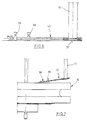
- zeigt einen Teil des Rotors nach Fig. 1 in Seitenansicht mit einem Arm und einem Oberstempel.
- Fig. 3
- zeigt perspektivisch den Arm nach Fig. 2.
- Fig. 4
- zeigt eine ähnliche Darstellung wie Fig. 2 mit abgesenktem Oberstempel zur Fixierung des Preßlings.
- Fig. 5
- zeigt eine ähnliche Darstellung wie Fig. 2 und 4 während des Einpressens des Preßlings.
- Fig. 6
- zeigt die Beendigung des Einbringvorgangs des Preßlings.
- Fig. 7
- zeigt eine ähnliche Darstellung wie die vorausgehenden Figuren, jedoch mit hochgeschwenktem radialem Arm.
- Fig. 1
- shows schematically the top view of the rotor of a rotary press according to the invention.
- Fig. 2
- shows a part of the rotor of FIG. 1 in side view with an arm and an upper punch.
- Fig. 3
- shows in perspective the arm of FIG. 2nd
- Fig. 4
- shows a similar representation as Fig. 2 with the lower punch for fixing the compact.
- Fig. 5
- shows a similar representation as Fig. 2 and 4 during the pressing of the compact.
- Fig. 6
- shows the completion of the insertion process of the compact.
- Fig. 7
- shows a representation similar to the previous figures, but with the radial arm pivoted up.
In Fig. 1 ist bei 10 der Rotor einer Rundläuferpresse dargestellt, wobei jedoch die
Oberstempel und die zugehörige Stempelführung weggelassen sind. Man erkennt die
Matrizenbohrungen 12 auf einem Teilkreis der Matrizenscheibe des Rotors 10. Dem
Rotor 10 sind eine erste Befüllvorrichtung 16 und eine zweite Befüllvorrichtung 18
zugeordnet. Sie sind stationär und dienen dazu, pulverförmiges Material in die
Matrizenbohrungen 12 einzufüllen, wobei die nicht gezeigten Unterstempel die
Matrizenbohrungen nach unten verschließen. Im Anschluß an die Befüllvorrichtung
16 ist eine Druckstation 20 zu erkennen, welche die Ober- und Unterstempel mit
Hilfe von Druckrollen zusammenführt, um das eingefüllte Material zu verpressen.
Im Anschluß an die Befüllvorrichtung 18 ist eine weitere Druckstation 22 vorgesehen.
Zwei weitere Preßstationen 24 und 26 befinden sich im größeren Umfangsabstand
am Rotor 10. Bei dem Preßvorgang dreht sich der Rotor entgegengesetzt
dem Uhrzeigersinn. Mit den bisher beschriebenen an sich bekannten Maßnahmen
läßt sich mithin eine Zweischichttablette pressen, welche bei 28 entfernt wird.In Fig. 1 the rotor of a rotary press is shown at 10, but the
Upper stamp and the associated stamp guide are omitted. You can see that
Die bores 12 on a pitch circle of the die plate of the
Man erkennt in der Darstellung nach Fig. 1 einen Auflagerring 30, der durch ein
stationäres Ringsegment 32, das sich von der annähernd 6-Uhr-Position bis zur
annähernd 2-Uhr-Position erstreckt, außen begrenzt ist. In diesem Bereich ist mithin
ein Ringabschnittskanal gebildet, in den runde Preßlinge 34 oder Kerne eingelegt
werden können. Zur Sicherung der Kerne 34 in ihre Lage kann an der Innenseite des
Auflagerrings 30 ein Begrenzungsring 36 vorgesehen werden, der mit kleinen Ausnehmungen
versehen ist, durch welche die Preßlinge 34 in Umfangsrichtung festgelegt
sind. Die Ablage der Preßlinge 34 erfolgt in annähernd radialer Ausrichtung zu
den Matrizenbohrungen.1 shows a
Jeder Matrizenbohrung 12 ist ein radialer Arm 40 zugeordnet, dessen Aufbau näher
in Fig. 3 zu erkennen ist. Jeder Arm 40 weist zwei parallele Rohrstücke 42, 44 auf,
die an den Enden Greifabschnitte 46, 48 halten. Die Greifabschnitte 46, 48 weisen
Greifansätze 50, 52 auf, die ausgetauscht werden können, um eine Anpassung an die
Außenkontur des Preßlings 34 vornehmen zu können. Am Greifabschnitt 48 ist eine
Führungsstange 54 angebracht, die mit einer Führungsbohrung des Greifabschnitts
46 zusammenwirkt. An den Enden der Rohrstücke 42, 44 sind Kurvenfolger 56, 58
angebracht. Die Rohrstücke 42, 44 wirken teleskopisch mit Stangen 60, 62 zusammen,
die an einem Block 64 um eine horizontale Achse schwenkbar angelenkt sind.
Die Blöcke 64 sind fest auf dem Rotor 10 angebracht, wie in Fig. 1 zu erkennen.
Oberhalb der Matrizenscheibe mit den Matrizenbohrungen 12 ist eine Scheibe (nicht
gezeigt) stationär angeordnet. Sie wird von oben durch den Innenraum des Rotors
gehalten, der fliegend gelagert ist. Eine fliegende Lagerung von Rotoren von Rundläuferpressen
ist an sich bekannt. Die stationäre Scheibe weist zwei Ringnuten auf,
die in Fig. 1 bei 66 und 68 angedeutet ist. Mit den Ringnuten 66, 68 wirken die Kurvenfolger
56, 58 zusammen.A
Man erkennt ferner aus Fig. 1, daß von der Preßstation 24 bis zur Preßstation 22
entgegengesetzt der Uhrzeigerrichtung gesehen die Greifabschnitte 46, 48 sich radial
auf gegenüberliegende Seiten der Matrizenbohrungen in geöffneter Position befinden.
Nachdem hinter der Preßstation 22 die Preßlinge 34 eingelegt werden, beginnt
aufgrund des geänderten Verlaufs der Nuten 66, 68 eine Verstellung der Greifabschnitte
46, 48 radial nach außen, bis sie auf gegenüberliegenden Seiten des Preßlings
liegen. Dies ist in Fig. 1 kurz hinter der 3-Uhr-Stellung der Fall. Eine nicht
gezeigte Anhebevorrichtung in Form von Stiften unterhalb der Positionen der Preßlinge
34, die mit einer stationären Steuerkurve zusammenwirken, hebt den Preßling
34 etwas an zwischen die Ansätze 50, 52 der Greifabschnitte 46, 48. Gleichzeitig
werden die Greifabschnitte aufeinander zugefahren, um den Preßling zu erfassen. Ist
dies geschehen, wie in der 2-Uhr-Stellung in Fig. 1 zu erkennen, erfolgt
anschließend das gemeinsame radiale Einwärtsfahren der Greifabschnitte 46, 48, bis
der Kern mit der Matrizenbohrung ausgerichtet ist. Dies ist in der 1-Uhr-Stellung
nach Fig. 1 zu erkennen. Gleichzeitig wird der Oberstempel, der der Matrizenbohrung
zugekehrt ist, abgesenkt. Dies ist in Fig. 2 zu erkennen. Der Oberstempel ist
mit 70 bezeichnet. In Fig. 4 ist zu erkennen, daß der Oberstempel 70 weiter abgesenkt
ist und nunmehr den Preßling 30 festhält. Die Greifabschnitte 46, 48 können
nun mit Hilfe der Steuernuten 66, 68 auseinander gefahren werden, und der Oberstempel
70 preßt den Preßling 30 in den gepreßten Tablettenabschnitt 72 in der
Matrizenbohrung 12 gegen den Unterstempel 74. Dieser Vorgang erfolgt in den
Preßstationen 24, 26. Anschließend kann mit Hilfe der zweiten Befüllvorrichtung 16
weiteres pulverförmiges Material eingefüllt werden, so daß eine zweite Schicht
oberhalb des Preßlings 30 gebildet ist.1 that from the
In Fig. 7 ist zu erkennen, daß die Arme 40 auch nach oben geschwenkt werden können,
um etwa den Befüllvorrichtungen oder Befüllschuhen 16, 18 auszuweichen. Die
Greifabschnitte sind auseinander gefahren, wie auch in Fig. 1 zu erkennen, so daß
der Oberstempel 70 durch den Abstand zwischen den Greifabschnitten 46, 48
geführt sein kann.In Fig. 7 it can be seen that the
Claims (6)
Applications Claiming Priority (2)
| Application Number | Priority Date | Filing Date | Title |
|---|---|---|---|
| DE10026731A DE10026731C2 (en) | 2000-05-17 | 2000-05-17 | Rotary tablet press for the production of multilayer tablets |
| DE10026731 | 2000-05-17 |
Publications (2)
| Publication Number | Publication Date |
|---|---|
| EP1155811A2 true EP1155811A2 (en) | 2001-11-21 |
| EP1155811A3 EP1155811A3 (en) | 2003-07-30 |
Family
ID=7644058
Family Applications (1)
| Application Number | Title | Priority Date | Filing Date |
|---|---|---|---|
| EP01101231A Withdrawn EP1155811A3 (en) | 2000-05-17 | 2001-01-19 | Rotary tabletting press for manufacturing multi-layer tablets |
Country Status (3)
| Country | Link |
|---|---|
| US (1) | US6527537B2 (en) |
| EP (1) | EP1155811A3 (en) |
| DE (1) | DE10026731C2 (en) |
Cited By (3)
| Publication number | Priority date | Publication date | Assignee | Title |
|---|---|---|---|---|
| WO2006138090A1 (en) * | 2005-06-17 | 2006-12-28 | Owens-Illinois Closure Inc. | Vertical wheel machine and method for compression molding sealing liners |
| EP2165826A3 (en) * | 2008-09-19 | 2011-01-19 | ELIZABETH-HATA International | Tablet press assembly |
| US9114585B2 (en) | 2008-04-18 | 2015-08-25 | Korsch Ag | Method and device for inserting inserts (cores) into female molds of a rotary tableting press |
Families Citing this family (6)
| Publication number | Priority date | Publication date | Assignee | Title |
|---|---|---|---|---|
| KR100463775B1 (en) * | 2000-12-04 | 2004-12-29 | 가부시키가이샤 무라타 세이사쿠쇼 | Powder feeding apparatus and powder forming apparatus |
| JP3780842B2 (en) * | 2000-12-04 | 2006-05-31 | 株式会社村田製作所 | Powder molding apparatus and powder molding method |
| DE10321754B4 (en) * | 2003-05-15 | 2006-03-02 | Fette Gmbh | Method and device for placing solid components (depositors) in dies of a rotary tableting press |
| US7481646B2 (en) * | 2005-06-17 | 2009-01-27 | Rexam Closure Systems Inc. | Compression molding machine |
| DE102005030312B4 (en) * | 2005-06-23 | 2011-05-05 | Korsch Ag | Rotary tabletting machine and method for producing a multilayer tablet |
| DE102013114693A1 (en) * | 2013-12-20 | 2015-06-25 | Fette Engineering GmbH | Stuffing stamp station and method of filling capsules in a stuffing stamp station |
Citations (2)
| Publication number | Priority date | Publication date | Assignee | Title |
|---|---|---|---|---|
| US5088915A (en) * | 1988-06-08 | 1992-02-18 | Korsch Ohg Maschinenfabrik | Coated-core press |
| DE19815081A1 (en) * | 1997-04-08 | 1998-10-15 | Mg 2 Spa | Assembly for production of compressed pharmaceutical tablets |
Family Cites Families (5)
| Publication number | Priority date | Publication date | Assignee | Title |
|---|---|---|---|---|
| US3332367A (en) * | 1965-07-15 | 1967-07-25 | Upjohn Co | Apparatus for making tablets |
| US4193502A (en) * | 1977-04-29 | 1980-03-18 | Westinghouse Electric Corp. | Pellet dimension checker |
| DE3930127A1 (en) * | 1989-09-09 | 1991-03-21 | Fette Wilhelm Gmbh | CIRCULAR TABLETING MACHINE |
| DE4025484C1 (en) * | 1990-08-08 | 1991-10-10 | Korsch Maschfab | |
| JPH09511183A (en) * | 1994-01-15 | 1997-11-11 | コルシュ プレッセン ゲーエムベーハ | Device to fix the molds |
-
2000
- 2000-05-17 DE DE10026731A patent/DE10026731C2/en not_active Expired - Fee Related
-
2001
- 2001-01-19 EP EP01101231A patent/EP1155811A3/en not_active Withdrawn
- 2001-05-10 US US09/852,823 patent/US6527537B2/en not_active Expired - Fee Related
Patent Citations (2)
| Publication number | Priority date | Publication date | Assignee | Title |
|---|---|---|---|---|
| US5088915A (en) * | 1988-06-08 | 1992-02-18 | Korsch Ohg Maschinenfabrik | Coated-core press |
| DE19815081A1 (en) * | 1997-04-08 | 1998-10-15 | Mg 2 Spa | Assembly for production of compressed pharmaceutical tablets |
Cited By (8)
| Publication number | Priority date | Publication date | Assignee | Title |
|---|---|---|---|---|
| WO2006138090A1 (en) * | 2005-06-17 | 2006-12-28 | Owens-Illinois Closure Inc. | Vertical wheel machine and method for compression molding sealing liners |
| US7556488B2 (en) | 2005-06-17 | 2009-07-07 | Rexam Closure Inc. | Vertical wheel machine and method for compression molding sealing liners |
| US9114585B2 (en) | 2008-04-18 | 2015-08-25 | Korsch Ag | Method and device for inserting inserts (cores) into female molds of a rotary tableting press |
| EP2110232B1 (en) * | 2008-04-18 | 2016-09-14 | Korsch AG | Device for inserting inlays into the matrices of a rotary tablet press |
| EP2165826A3 (en) * | 2008-09-19 | 2011-01-19 | ELIZABETH-HATA International | Tablet press assembly |
| US8062015B2 (en) | 2008-09-19 | 2011-11-22 | Elizabeth-Hata International | Tablet press assembly |
| US8562322B2 (en) | 2008-09-19 | 2013-10-22 | Elizabeth-Hata International | Aspects of a press assembly |
| US9011128B2 (en) | 2008-09-19 | 2015-04-21 | Elizabeth-Hata International | Aspects of a press assembly |
Also Published As
| Publication number | Publication date |
|---|---|
| US20010046527A1 (en) | 2001-11-29 |
| EP1155811A3 (en) | 2003-07-30 |
| DE10026731C2 (en) | 2002-08-14 |
| DE10026731A1 (en) | 2001-11-29 |
| US6527537B2 (en) | 2003-03-04 |
Similar Documents
| Publication | Publication Date | Title |
|---|---|---|
| DE2363948C2 (en) | Device for compression molding of helical or helical toothed gears with different toothings | |
| EP0349777B1 (en) | Core-encapsulating press | |
| DE2604648C2 (en) | Rotary press | |
| DE2160742A1 (en) | Device for separating tight and leaky cans | |
| DE10026731C2 (en) | Rotary tablet press for the production of multilayer tablets | |
| EP1893402A1 (en) | Rotary pelleting machine and method for producing a multi-layer pellet | |
| WO2016009248A2 (en) | Method for producing a moulded piece | |
| EP2082867B1 (en) | Tablet press | |
| EP1153735B1 (en) | Punch for rotary press | |
| DE3432992C2 (en) | Device for metering a predetermined amount of powder | |
| DE1602607A1 (en) | Conveyor device | |
| DE2133720C3 (en) | Device for assembling a radial roller bearing | |
| EP2036710B1 (en) | Rotor for a rotary tablet compactor | |
| DE19739515A1 (en) | Forging device for ring gear | |
| DE102011101286B4 (en) | Rotary press and method for operating a rotary press | |
| DE10321754B4 (en) | Method and device for placing solid components (depositors) in dies of a rotary tableting press | |
| DE2950674A1 (en) | Turntable for work transfer assembly - is rotated stepwise via maltese cross drive and transmission contg. meshing elliptical gear wheels | |
| DE1940567A1 (en) | Device for the fully automatic assembly of electrical components | |
| DE4114025C1 (en) | Labelling machine with work retaining plate(s) - has plunger inner and outer parts, between which is releasable lock | |
| WO2016156306A1 (en) | Rotary press comprising at least one compression roll station mountable on a support plate, and method for attaching and detaching the compression roll station | |
| DE2166333C3 (en) | ||
| DE1023191B (en) | Process and device for the production of coated tablets | |
| DE1479053C3 (en) | Method and device for producing a molding compound cake that can be transferred to a record press | |
| DE19711759C2 (en) | Press device for the plastic deformation of materials, in particular thermoplastic plastic strips | |
| DE1959647C3 (en) | Device for pressing helical workpieces, in particular gear wheels |
Legal Events
| Date | Code | Title | Description |
|---|---|---|---|
| PUAI | Public reference made under article 153(3) epc to a published international application that has entered the european phase |
Free format text: ORIGINAL CODE: 0009012 |
|
| 17P | Request for examination filed |
Effective date: 20010126 |
|
| AK | Designated contracting states |
Kind code of ref document: A2 Designated state(s): AT BE CH CY DE DK ES FI FR GB GR IE IT LI LU MC NL PT SE TR |
|
| AX | Request for extension of the european patent |
Free format text: AL;LT;LV;MK;RO;SI |
|
| RAP1 | Party data changed (applicant data changed or rights of an application transferred) |
Owner name: FETTE GMBH |
|
| PUAL | Search report despatched |
Free format text: ORIGINAL CODE: 0009013 |
|
| AK | Designated contracting states |
Designated state(s): AT BE CH CY DE DK ES FI FR GB GR IE IT LI LU MC NL PT SE TR |
|
| AX | Request for extension of the european patent |
Extension state: AL LT LV MK RO SI |
|
| STAA | Information on the status of an ep patent application or granted ep patent |
Free format text: STATUS: THE APPLICATION HAS BEEN WITHDRAWN |
|
| 18W | Application withdrawn |
Effective date: 20030905 |