EP1155750B1 - Zentrierbare Spaltdichtung, insbesondere für Mühlen und Sichter - Google Patents
Zentrierbare Spaltdichtung, insbesondere für Mühlen und Sichter Download PDFInfo
- Publication number
- EP1155750B1 EP1155750B1 EP01110802A EP01110802A EP1155750B1 EP 1155750 B1 EP1155750 B1 EP 1155750B1 EP 01110802 A EP01110802 A EP 01110802A EP 01110802 A EP01110802 A EP 01110802A EP 1155750 B1 EP1155750 B1 EP 1155750B1
- Authority
- EP
- European Patent Office
- Prior art keywords
- annular gap
- seal according
- gap seal
- intermediate piece
- boundary wall
- Prior art date
- Legal status (The legal status is an assumption and is not a legal conclusion. Google has not performed a legal analysis and makes no representation as to the accuracy of the status listed.)
- Expired - Lifetime
Links
- 238000007789 sealing Methods 0.000 title claims description 32
- 239000012530 fluid Substances 0.000 claims description 5
- 238000010327 methods by industry Methods 0.000 claims description 4
- 238000000926 separation method Methods 0.000 claims 1
- 125000006850 spacer group Chemical group 0.000 description 11
- 238000004519 manufacturing process Methods 0.000 description 4
- 239000000463 material Substances 0.000 description 4
- 239000002245 particle Substances 0.000 description 4
- 238000010276 construction Methods 0.000 description 3
- 230000000694 effects Effects 0.000 description 2
- 238000011010 flushing procedure Methods 0.000 description 2
- 230000015572 biosynthetic process Effects 0.000 description 1
- 238000004140 cleaning Methods 0.000 description 1
- 230000001419 dependent effect Effects 0.000 description 1
- 238000011161 development Methods 0.000 description 1
- 230000018109 developmental process Effects 0.000 description 1
- 238000006073 displacement reaction Methods 0.000 description 1
- 238000010297 mechanical methods and process Methods 0.000 description 1
- 230000005226 mechanical processes and functions Effects 0.000 description 1
- 238000010926 purge Methods 0.000 description 1
- 238000003860 storage Methods 0.000 description 1
Images




Classifications
-
- B—PERFORMING OPERATIONS; TRANSPORTING
- B07—SEPARATING SOLIDS FROM SOLIDS; SORTING
- B07B—SEPARATING SOLIDS FROM SOLIDS BY SIEVING, SCREENING, SIFTING OR BY USING GAS CURRENTS; SEPARATING BY OTHER DRY METHODS APPLICABLE TO BULK MATERIAL, e.g. LOOSE ARTICLES FIT TO BE HANDLED LIKE BULK MATERIAL
- B07B11/00—Arrangement of accessories in apparatus for separating solids from solids using gas currents
-
- B—PERFORMING OPERATIONS; TRANSPORTING
- B07—SEPARATING SOLIDS FROM SOLIDS; SORTING
- B07B—SEPARATING SOLIDS FROM SOLIDS BY SIEVING, SCREENING, SIFTING OR BY USING GAS CURRENTS; SEPARATING BY OTHER DRY METHODS APPLICABLE TO BULK MATERIAL, e.g. LOOSE ARTICLES FIT TO BE HANDLED LIKE BULK MATERIAL
- B07B7/00—Selective separation of solid materials carried by, or dispersed in, gas currents
- B07B7/08—Selective separation of solid materials carried by, or dispersed in, gas currents using centrifugal force
- B07B7/083—Selective separation of solid materials carried by, or dispersed in, gas currents using centrifugal force generated by rotating vanes, discs, drums, or brushes
Definitions
- the invention relates to an annular gap seal for in particular process engineering machines according to the preamble of claim 1, and the use of an annular gap seal.
- two rooms must be standing and standing a rotating wall will be sealed against each other, and while preventing wear on the respective rotating working part or the standing boundary wall.
- the wear can in general only can be prevented by a contactless seal.
- the sealing gap In order to obtain a sufficient sealing effect between the two rooms, the sealing gap must be as narrow as possible. In addition, it is Commonly, such sealing gaps with the help of a fluid flow, e.g. Purge air, too flow through, whereby an additional non-contact sealing effect is achieved.
- a fluid flow e.g. Purge air
- One area of application for such contactless gap seals is process engineering machines in which in a work area by a rotating working part, e.g. a mill rotor or a classifier wheel, on a product is acted mechanically.
- a rotating working part e.g. a mill rotor or a classifier wheel
- one product to be viewed the material to be viewed, is replaced by one Sifter wheel rotating in axis and one rotating exposed to superimposed air flow. This flow of visible air runs from the outside inside, against the centrifugal force through the classifier wheel. Due to the Mode of operation of the classifier wheel only particles with smaller grain size enter the inside of the classifier wheel and particles of larger grain size are turned outside rejected.
- the particles of smaller grain size sucked into the interior of the classifier wheel are called fines and must come from inside the classifier wheel via a fine material discharge, e.g. discharged a fixed pipe socket become.
- the particles of larger grain size are called coarse material and should remain in the work area.
- the work area in which both fine and coarse goods are available must be from a second room, the fines discharge room, in which only fines are available may be sealed.
- the seal is made between the fixed one Discharge area and the rotating classifier wheel.
- the non-contact one Gasket is required to prevent wear of the rotating classifier wheel prevent.
- a viewing device is disclosed in the prior art according to DE 39 28 292 A1, which involves the formation of a gap seal between a fine material outlet pipe and a classifier wheel.
- annular disc which is in a ring the chamber surrounding the outlet pipe is adjustable. This measure will the sealing gap opposite the classifier wheel can be adjusted in its axial direction.
- the adjustable washer is evenly distributed over the circumference by several distributed, fixed bolts carried. By axially adjusting the bolts the washer is adjusted in the axial direction and thus the radial one Sealing gap set.
- the adjustability of the washer in the axial direction serves to determine the size of the to be able to adjust radially extending sealing gap.
- the ring washer there is supported by ring seals in a chamber, the position of the Washer is determined by the position of the outlet pipe, not by the position the classifier wheel.
- the annular gap between the working part and the adjacent one Adjust the housing with difficulty.
- the manufacturing tolerances of the individual parts are namely in the case of economical production processes too roughly in the assembled state to be able to reach uniform and narrow gaps. Sealing gap and especially flushing gaps that are generated across large components, are subject to a high degree of thermal expansion and can during vary considerably in different operating states.
- the object of the invention is therefore to provide an annular gap seal that very narrow and precisely positioned column allows the fixed Sealing surface can be centered relative to the rotating sealing surface.
- the sealing surfaces correspond to the boundary walls of the sealing gap.
- annular disc hereinafter defined as an intermediate piece, in the finished and assembled condition within the machine retrospectively in relation to the rotating work part can be positioned and centered, manufacturing and Operating tolerances can be compensated in a simple manner.
- the intermediate piece according to the invention has the further advantage that the gap-forming functional surfaces (outer radius of the rotating wall of the Working part and the inner radius of the annular intermediate piece) of sealing components coupled over the shortest possible connection distance are, so that thermal expansion occurs only little influence on the gap width to have.
- An additional advantage is the fact that the rotating working part together with the corresponding gap-forming functional area (ring-shaped intermediate piece) e.g. for cleaning purposes, on and off can be expanded. Another setting is the width of the Annular gap is no longer necessary after reassembly.
- An elastic sealing element seals between the standing boundary wall and the intermediate piece.
- This seal can be a simple O-ring seal as both opposite sealing surfaces are standing parts. Depending on the application can this standing seal axially or radially with a sealing surface interact.
- the ring-shaped intermediate piece detachably connected to the setting aid together with the spacers.
- the annular Remove and reinstall the spacer together with the spacers without having to re-center the annular gap.
- the coaxial Position of the intermediate piece due to the still fixed position of the Reproducible recordings and the setting aid.
- a radially or axially sealing Hose seal provided that the axially or radially sealing ring seal replaced. Due to the changed position of the seal, this embodiment is required not the otherwise necessary accuracy in the height tolerance. Both the spacer and the standing boundary wall can also be made simpler.
- this is between the rotating one Boundary wall, i.e. the working part, and its drive shaft arranged.
- the through the Adjustment aid realized axial displacement of the rotating wall or Working part could also by a slidable arrangement of the storage Drive shaft of the working part.
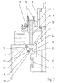
- the annular intermediate piece (1) is of, for example, three spacers (5) evenly distributed over the circumference worn, which are supported on the housing (8).
- the spacers (5) are stored in receptacles (7).
- the spacers can be adjusted by adjusting the setting aid (9) (5) together with the intermediate piece (1) can be moved axially.
- a first (10) and optionally a second paragraph (11) are on the rotating boundary wall (12) of the working part (4) attached. If the intermediate piece (1) with the help of Adjustment aid (9) axially raised, so the inner ring surface of the Intermediate piece (1) to lie on paragraphs (10, 11).
- the outside diameter the shoulders (10,11) is the inner diameter of the annular intermediate piece (1) adjusted. With this fit, the ring-shaped intermediate piece (1) aligned coaxially to the working part (4).
- the radially displaceable pictures (7) shift accordingly.
- the receptacles (7) can be rigidly fixed using the fastening means (13), so that they are in position relative to the housing (8) and the working part (4) no longer change.
- the annular intermediate piece (1) is now coaxial aligned.
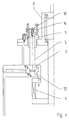
- the intermediate piece (1) is together with the spacers (5) are lowered and adjusted by adjusting the setting aid (9) a position as shown in Fig. 2.
- the intermediate piece (1) is in Contact with the corresponding paragraphs (14, 15) on the standing Boundary wall (3).
- An elastic sealing element (17) seals between the standing boundary wall (3) and the intermediate piece (1).
- the gap seal is designed as a flushable annular gap (2a, 2b)
- a Flushing fluid via the supply line (19) into the interior of the housing (8) initiated and via one or more passages distributed over the circumference (21) passed into the area of the rinsing gap.
- the sealing of the Supply line (19) and passages (21) formed fluid channel via a above and an annular seal (17) formed below the fluid channel.
- FIG. 3 and 4 show a training variant in which the ring-shaped Intermediate piece (1) together with the spacers (5) can be detached using the adjustment aid (9) via a first connection means (16) and via a second connection means (18) is connected.
- 5 and 6 is a radially sealing hose seal as a sealing variant (20) shown, which replaces the axially sealing ring seal (17).
- the adjustment aid (9) is between the rotating boundary wall (3), i.e. the working part (4), and its drive shaft (6) arranged.
- FIG. 7 shows the annular gap seal according to the invention in a centrifugal classifier for mechanical process engineering machines.
Landscapes
- Crushing And Grinding (AREA)
- Sealing Devices (AREA)
- Sealing Using Fluids, Sealing Without Contact, And Removal Of Oil (AREA)
- Sealing Material Composition (AREA)
Description
- 1
- Zwischenstück
- 2
- Ringspalt
- 3
- stehende Begrenzungswand
- 4
- Arbeitsteil
- 5
- Distanzteil
- 6
- Antriebswelle
- 7
- Aufnahme
- 8
- Gehäuse
- 9
- Einstellhilfe
- 10
- erster Absatz
- 11
- zweiter Absatz
- 12
- rotierende Begrenzungswand
- 13
- Befestigungsmittel
- 14
- erster korrespondierender Absatz
- 15
- zweiter korrespondierender Absatz
- 16
- erstes Verbindungsmittel
- 17
- elastisches Dichtelement
- 18
- zweites Verbindungsmittel
- 19
- Versorgungsleitung
- 20
- Schlauchdichtung
- 21
- Durchlaß
Claims (15)
- Ringspalt-Dichtung für insbesondere verfahrenstechnische Maschinen bei denen in einem Arbeitsraum durch ein rotierendes Arbeitsteil (4) auf ein Produkt mechanisch eingewirkt wird, zum Trennen zweier Räume mittels eines von einer stehenden (3) und einer rotierenden (12) Begrenzungswand begrenzten Ringspaltes (2a, 2b), mit einem Zwischenstück (1) zwischen den Begrenzungswänden (3,12), das in einer Betriebsposition sowohl mit der stehenden Begrenzungswand (3) berührend abdichtet, als auch mit der rotierenden Begrenzungswand (12) den Ringspalt (2a, 2b) bildet dadurch gekennzeichnet, daß das Zwischenstück (1) aus der Betriebsposition in eine Zentrierposition verschiebbar ist, zum Zentrieren des Zwischenstücks (1) koaxial zur rotierenden Begrenzungswand.
- Ringspalt-Dichtung nach Anspruch 1, dadurch gekennzeichnet, daß der Ringspalt (12) in axialer Richtung verläuft
- Ringspalt-Dichtung nach Anspruch 1 oder 2, dadurch gekennzeichnet, daß das Zwischenstück (1) in axialer Richtung verschieblich ist.
- Ringspalt-Dichtung nach Anspruch 1 bis 3, dadurch gekennzeichnet, daß das Zwischenstück (1) in der Zentrierposition an mindestens einem Absatz (10,11) der rotierenden Wand (12) zentrierbar ist.
- Ringspalt-Dichtung nach Anspruch 1 bis 4, dadurch gekennzeichnet, daß das Zwischenstück (1) mindestens ein elastisches Dichtelement (17) aufweist, die in der Betriebsposition mit mindestens einem korrespondierendem Absatz (14,15) an der stehenden Begrenzungswand (3) in abdichtendem Kontakt steht.
- Ringspalt-Dichtung nach Anspruch 5, dadurch gekennzeichnet, daß das elastische Dichtelement (17) eine Schlauch- oder O-Ring-Dichtung ist.
- Ringspalt-Dichtung nach Anspruch 1 bis 6, dadurch gekennzeichnet, daß das Zwischenstück (1) ein oder mehrere Durchlässe (21) aufweist, über die der Ringspalt (2a, 2b) aus mindestens einer Versorgungsleitung (19) mit einem Fluid spülbar ist.
- Ringspalt-Dichtung nach Anspruch 7, dadurch gekennzeichnet, daß die Durchlässe (21) und/oder die Versorgungsleitungen (19) zwischen mindestens zwei der mehreren elastischen Dichtelemente (17) angeordnet sind.
- Ringspalt-Dichtung nach Anspruch 3, dadurch gekennzeichnet, daß das Zwischenstück (1) mit einem axial verschieblichen Distanzteil (5) verbunden ist.
- Ringspalt-Dichtung nach Anspruch 9, dadurch gekennzeichnet, daß das Distanzteil (5) in einer in radialer Ebene verschieblichen Aufnahme (7) gelagert ist.
- Ringspalt-Dichtung nach Anspruch 10, dadurch gekennzeichnet, daß die Aufnahme (7) durch ein Befestigungsmittel (13) starr in Bezug auf die stehende Begrenzungswand (3) arretierbar ist.
- Ringspalt-Dichtung nach Anspruch 11, dadurch gekennzeichnet, daß das Distanzteil (5) über eine Einstellhilfe (9) axial verstellbar und/oder in unterschiedlichen Höhen axial arretierbar ist.
- Ringspalt-Dichtung nach Anspruch 12, dadurch gekennzeichnet, daß das Distanzteil (5) über Verbindungsmittel (16,18) lösbar mit der Einstellhilfe (9) verbunden ist.
- Ringspalt-Dichtung nach Anspruch 13, dadurch gekennzeichnet, daß die Einstellhilfe (9) zwischen rotierender Begrenzungswand (12) und deren Antriebswelle (6) angeordnet ist.
- Verwendung einer Ringspalt-Dichtung nach Anspruch 1 bis 14, in einer Mühle oder einem Sichter.
Applications Claiming Priority (2)
| Application Number | Priority Date | Filing Date | Title |
|---|---|---|---|
| DE10024774 | 2000-05-19 | ||
| DE10024774A DE10024774A1 (de) | 2000-05-19 | 2000-05-19 | Zentrierbare Spaltdichtung,insbesondere für Mühlen und Sichter |
Publications (2)
| Publication Number | Publication Date |
|---|---|
| EP1155750A1 EP1155750A1 (de) | 2001-11-21 |
| EP1155750B1 true EP1155750B1 (de) | 2003-08-27 |
Family
ID=7642772
Family Applications (1)
| Application Number | Title | Priority Date | Filing Date |
|---|---|---|---|
| EP01110802A Expired - Lifetime EP1155750B1 (de) | 2000-05-19 | 2001-05-04 | Zentrierbare Spaltdichtung, insbesondere für Mühlen und Sichter |
Country Status (3)
| Country | Link |
|---|---|
| EP (1) | EP1155750B1 (de) |
| AT (1) | ATE248033T1 (de) |
| DE (2) | DE10024774A1 (de) |
Families Citing this family (3)
| Publication number | Priority date | Publication date | Assignee | Title |
|---|---|---|---|---|
| EP1852189A3 (de) | 2006-05-06 | 2008-01-23 | HOSOKAWA ALPINE Aktiengesellschaft | Anlagenkonzept für Mühlen und Sichter mit Magnetlagerspindelantrieb |
| CN108043566B (zh) * | 2017-12-13 | 2020-02-18 | 马鞍山市荣亿密封材料有限责任公司 | 一种主轴密封监控装置 |
| CN111841858B (zh) * | 2020-07-28 | 2021-10-08 | 蓬莱沈蓬建材有限公司 | 一种自动上料的矿粉生产线 |
Family Cites Families (2)
| Publication number | Priority date | Publication date | Assignee | Title |
|---|---|---|---|---|
| FR2625925B1 (fr) * | 1988-01-18 | 1991-11-15 | Onoda Cement Co Ltd | Dispositif de triage de poudre |
| DE3928292A1 (de) * | 1989-08-26 | 1991-02-28 | Nied Roland | Verschleissanzeige |
-
2000
- 2000-05-19 DE DE10024774A patent/DE10024774A1/de not_active Withdrawn
-
2001
- 2001-05-04 EP EP01110802A patent/EP1155750B1/de not_active Expired - Lifetime
- 2001-05-04 DE DE50100537T patent/DE50100537D1/de not_active Expired - Fee Related
- 2001-05-04 AT AT01110802T patent/ATE248033T1/de not_active IP Right Cessation
Also Published As
| Publication number | Publication date |
|---|---|
| EP1155750A1 (de) | 2001-11-21 |
| ATE248033T1 (de) | 2003-09-15 |
| DE50100537D1 (de) | 2003-10-02 |
| DE10024774A1 (de) | 2001-11-22 |
Similar Documents
| Publication | Publication Date | Title |
|---|---|---|
| DE2558682C3 (de) | Filtrationsapparat | |
| DE3828363C2 (de) | ||
| EP0700723A1 (de) | Rührwerksmühle | |
| DE102013012765A1 (de) | Spindeleinheit für eine Bearbeitungseinrichtung mit einer Spindelarretierung | |
| DE2139497B2 (de) | Emulgier- und Dispergiervorrichtung | |
| EP3840620B1 (de) | Mahlwerk zum mahlen von mahlgut | |
| DE102011082867A1 (de) | Werkzeugspindel einer Honmaschine mit topfförmigem Halter für einen Honring | |
| DE2814958A1 (de) | Mikromahlmischer | |
| DE102009020708A1 (de) | Vorrichtung zum Zerkleinern von Aufgabegut | |
| EP1738864A2 (de) | Spannvorrichtung | |
| DE4338903A1 (de) | Zerkleinerungsmaschine und Einrichtung zur Einstellung des Spaltes einer solchen Zerkleinerungsmaschine | |
| DE102009022206B3 (de) | Lagerung mit einer Brems- und/oder Klemmvorrichtung | |
| EP1155750A1 (de) | Zentrierbare Spaltdichtung, insbesondere für Mühlen und Sichter | |
| DE102008049339A1 (de) | Vorrichtung zum Bearbeiten von Aufgabegut | |
| EP0652051A1 (de) | Trommelraumabdichtung für Stülpfilter-Zentrifuge | |
| DE2419355C2 (de) | Zentrifuge | |
| EP0640397A2 (de) | Rührwerksmühle | |
| DE3727173A1 (de) | Durch ein kompressibles fluid, insbesondere pneumatisch schaltbare kupplungs- und bremsvorrichtung | |
| EP4032615B1 (de) | Rührwerksmühle | |
| CH616213A5 (de) | ||
| DE4022902A1 (de) | Mahlvorrichtung | |
| EP0355285A2 (de) | Vorrichtung zum Trennen einer Suspension | |
| DE4332549A1 (de) | Rührwerksmühle | |
| DE3834456C2 (de) | ||
| EP2185287B1 (de) | Schwingmühle |
Legal Events
| Date | Code | Title | Description |
|---|---|---|---|
| PUAI | Public reference made under article 153(3) epc to a published international application that has entered the european phase |
Free format text: ORIGINAL CODE: 0009012 |
|
| AK | Designated contracting states |
Kind code of ref document: A1 Designated state(s): AT BE CH CY DE DK ES FI FR GB GR IE IT LI LU MC NL PT SE TR |
|
| AX | Request for extension of the european patent |
Free format text: AL;LT;LV;MK;RO;SI |
|
| 17P | Request for examination filed |
Effective date: 20020209 |
|
| AKX | Designation fees paid |
Free format text: AT BE CH CY DE DK ES FI FR GB GR IE IT LI LU MC NL PT SE TR |
|
| AXX | Extension fees paid |
Free format text: AL PAYMENT 20020521;LT PAYMENT 20020521;LV PAYMENT 20020521;MK PAYMENT 20020521;RO PAYMENT 20020521;SI PAYMENT 20020521 |
|
| DAX | Request for extension of the european patent (deleted) | ||
| GRAH | Despatch of communication of intention to grant a patent |
Free format text: ORIGINAL CODE: EPIDOS IGRA |
|
| GRAH | Despatch of communication of intention to grant a patent |
Free format text: ORIGINAL CODE: EPIDOS IGRA |
|
| GRAA | (expected) grant |
Free format text: ORIGINAL CODE: 0009210 |
|
| AK | Designated contracting states |
Designated state(s): AT BE CH CY DE DK ES FI FR GB GR IE IT LI LU MC NL PT SE TR |
|
| PG25 | Lapsed in a contracting state [announced via postgrant information from national office to epo] |
Ref country code: NL Free format text: LAPSE BECAUSE OF FAILURE TO SUBMIT A TRANSLATION OF THE DESCRIPTION OR TO PAY THE FEE WITHIN THE PRESCRIBED TIME-LIMIT Effective date: 20030827 Ref country code: IT Free format text: LAPSE BECAUSE OF FAILURE TO SUBMIT A TRANSLATION OF THE DESCRIPTION OR TO PAY THE FEE WITHIN THE PRESCRIBED TIME-LIMIT;WARNING: LAPSES OF ITALIAN PATENTS WITH EFFECTIVE DATE BEFORE 2007 MAY HAVE OCCURRED AT ANY TIME BEFORE 2007. THE CORRECT EFFECTIVE DATE MAY BE DIFFERENT FROM THE ONE RECORDED. Effective date: 20030827 Ref country code: ES Free format text: LAPSE BECAUSE OF FAILURE TO SUBMIT A TRANSLATION OF THE DESCRIPTION OR TO PAY THE FEE WITHIN THE PRESCRIBED TIME-LIMIT Effective date: 20030827 Ref country code: FR Free format text: LAPSE BECAUSE OF FAILURE TO SUBMIT A TRANSLATION OF THE DESCRIPTION OR TO PAY THE FEE WITHIN THE PRESCRIBED TIME-LIMIT Effective date: 20030827 Ref country code: CY Free format text: LAPSE BECAUSE OF FAILURE TO SUBMIT A TRANSLATION OF THE DESCRIPTION OR TO PAY THE FEE WITHIN THE PRESCRIBED TIME-LIMIT Effective date: 20030827 Ref country code: TR Free format text: LAPSE BECAUSE OF FAILURE TO SUBMIT A TRANSLATION OF THE DESCRIPTION OR TO PAY THE FEE WITHIN THE PRESCRIBED TIME-LIMIT Effective date: 20030827 Ref country code: FI Free format text: LAPSE BECAUSE OF FAILURE TO SUBMIT A TRANSLATION OF THE DESCRIPTION OR TO PAY THE FEE WITHIN THE PRESCRIBED TIME-LIMIT Effective date: 20030827 Ref country code: GB Free format text: LAPSE BECAUSE OF FAILURE TO SUBMIT A TRANSLATION OF THE DESCRIPTION OR TO PAY THE FEE WITHIN THE PRESCRIBED TIME-LIMIT Effective date: 20030827 Ref country code: IE Free format text: LAPSE BECAUSE OF FAILURE TO SUBMIT A TRANSLATION OF THE DESCRIPTION OR TO PAY THE FEE WITHIN THE PRESCRIBED TIME-LIMIT Effective date: 20030827 |
|
| REG | Reference to a national code |
Ref country code: GB Ref legal event code: FG4D Free format text: NOT ENGLISH |
|
| REG | Reference to a national code |
Ref country code: CH Ref legal event code: EP |
|
| REG | Reference to a national code |
Ref country code: IE Ref legal event code: FG4D Free format text: GERMAN |
|
| REF | Corresponds to: |
Ref document number: 50100537 Country of ref document: DE Date of ref document: 20031002 Kind code of ref document: P |
|
| PG25 | Lapsed in a contracting state [announced via postgrant information from national office to epo] |
Ref country code: DK Free format text: LAPSE BECAUSE OF FAILURE TO SUBMIT A TRANSLATION OF THE DESCRIPTION OR TO PAY THE FEE WITHIN THE PRESCRIBED TIME-LIMIT Effective date: 20031127 Ref country code: GR Free format text: LAPSE BECAUSE OF FAILURE TO SUBMIT A TRANSLATION OF THE DESCRIPTION OR TO PAY THE FEE WITHIN THE PRESCRIBED TIME-LIMIT Effective date: 20031127 Ref country code: SE Free format text: LAPSE BECAUSE OF FAILURE TO SUBMIT A TRANSLATION OF THE DESCRIPTION OR TO PAY THE FEE WITHIN THE PRESCRIBED TIME-LIMIT Effective date: 20031127 |
|
| PG25 | Lapsed in a contracting state [announced via postgrant information from national office to epo] |
Ref country code: PT Free format text: LAPSE BECAUSE OF FAILURE TO SUBMIT A TRANSLATION OF THE DESCRIPTION OR TO PAY THE FEE WITHIN THE PRESCRIBED TIME-LIMIT Effective date: 20040127 |
|
| NLV1 | Nl: lapsed or annulled due to failure to fulfill the requirements of art. 29p and 29m of the patents act | ||
| GBV | Gb: ep patent (uk) treated as always having been void in accordance with gb section 77(7)/1977 [no translation filed] |
Effective date: 20030827 |
|
| REG | Reference to a national code |
Ref country code: IE Ref legal event code: FD4D |
|
| PG25 | Lapsed in a contracting state [announced via postgrant information from national office to epo] |
Ref country code: AT Free format text: LAPSE BECAUSE OF NON-PAYMENT OF DUE FEES Effective date: 20040504 Ref country code: LU Free format text: LAPSE BECAUSE OF NON-PAYMENT OF DUE FEES Effective date: 20040504 |
|
| PG25 | Lapsed in a contracting state [announced via postgrant information from national office to epo] |
Ref country code: MC Free format text: LAPSE BECAUSE OF NON-PAYMENT OF DUE FEES Effective date: 20040531 Ref country code: BE Free format text: LAPSE BECAUSE OF NON-PAYMENT OF DUE FEES Effective date: 20040531 |
|
| PLBE | No opposition filed within time limit |
Free format text: ORIGINAL CODE: 0009261 |
|
| STAA | Information on the status of an ep patent application or granted ep patent |
Free format text: STATUS: NO OPPOSITION FILED WITHIN TIME LIMIT |
|
| 26N | No opposition filed |
Effective date: 20040528 |
|
| EN | Fr: translation not filed | ||
| BERE | Be: lapsed |
Owner name: *HOSOKAWA ALPINE A.G. & CO. OHG Effective date: 20040531 |
|
| PG25 | Lapsed in a contracting state [announced via postgrant information from national office to epo] |
Ref country code: LI Free format text: LAPSE BECAUSE OF NON-PAYMENT OF DUE FEES Effective date: 20050531 Ref country code: CH Free format text: LAPSE BECAUSE OF NON-PAYMENT OF DUE FEES Effective date: 20050531 |
|
| REG | Reference to a national code |
Ref country code: CH Ref legal event code: PL |
|
| PGFP | Annual fee paid to national office [announced via postgrant information from national office to epo] |
Ref country code: DE Payment date: 20080612 Year of fee payment: 8 |
|
| PG25 | Lapsed in a contracting state [announced via postgrant information from national office to epo] |
Ref country code: DE Free format text: LAPSE BECAUSE OF NON-PAYMENT OF DUE FEES Effective date: 20091201 |