EP1155642B1 - Cot assembly - Google Patents
Cot assembly Download PDFInfo
- Publication number
- EP1155642B1 EP1155642B1 EP00309057A EP00309057A EP1155642B1 EP 1155642 B1 EP1155642 B1 EP 1155642B1 EP 00309057 A EP00309057 A EP 00309057A EP 00309057 A EP00309057 A EP 00309057A EP 1155642 B1 EP1155642 B1 EP 1155642B1
- Authority
- EP
- European Patent Office
- Prior art keywords
- frame
- rod
- cot assembly
- cot
- bedding material
- Prior art date
- Legal status (The legal status is an assumption and is not a legal conclusion. Google has not performed a legal analysis and makes no representation as to the accuracy of the status listed.)
- Expired - Lifetime
Links
Images

Classifications
-
- A—HUMAN NECESSITIES
- A47—FURNITURE; DOMESTIC ARTICLES OR APPLIANCES; COFFEE MILLS; SPICE MILLS; SUCTION CLEANERS IN GENERAL
- A47C—CHAIRS; SOFAS; BEDS
- A47C19/00—Bedsteads
- A47C19/20—Multi-stage bedsteads; e.g. bunk beds; Bedsteads stackable to multi-stage bedsteads
- A47C19/202—Stacking or nesting bedsteads
Definitions
- the present invention relates generally to cots, and more particularly to an improved design for a cot assembly.
- the invention further relates to cots having various advantageous features, including a continuous bedding surface without gaps, a tensioning means for maintaining the bedding material in a taut condition, and the absence of exposed fasteners and the like.
- Cots provide a temporary sleeping surface positioned above the ground or floor.
- the cot is easily moved and transported and/or stored for later use.
- Cots find a wide variety of uses in many different activities for different ages and sizes of people. In one use, cots are used for camping or other outdoor sleeping settings to avoid contact with the ground. In another use, cots are used indoors by children or preschoolers when it is desired to provide a comfortable sleeping surface that is raised above the floor. Cots are more advantageous than mats or other devices that lie directly on the floor or ground for many reasons.
- they provide a more comfortable sleeping surface, allow air flow between the floor or ground and the sleeping surface, provide a sleeping surface for a person which is not in contact with the sleeping surface of another person, and do not expose the sleeping person to filth and/or pests which may be present on the floor or ground.
- U.S. Patent No. 5,003,649 to Kelly provides a nestable cot with a frame that allows a plurality of cots to be nestably stacked one on top of another.
- Each cot includes four corner connectors, each comer connector configured to receive a pedestal from a corresponding one of the comer connectors stacked thereupon.
- the stacked cots occupy a space that has a total height that is less than the sum of the individual heights of each cot, and are more easily stored and handled.
- Cots typically have a frame for supporting bedding material or fabric that extends between members of the frame.
- One of the problems with these prior art cots is that gaps are formed between the bedding material and the frame, and these gaps may pose a safety hazard, particularly for children.
- the potential for injury exists if a child inserts a hand, foot, head or other body part through the gap, where it may become stuck or may cause the child to trip and fall.
- the cot is more susceptible to being damaged. Cots having such gaps, particularly at the corners, have been prevalent in the prior art and means have not been provided for ensuring against such gaps.
- Another problem with prior art cots is related to maintaining the taut condition of the bedding material stretching between members of the frame. Since the sleeping surface is positioned above the floor or ground, when a child or person lies on the cot, the weight on the bedding material at the middle of the cot has the tendency to cause the bedding material to loosen and sag between the members of the frame. This problem worsens over time as the cot is repeatedly subjected to loading.
- the present invention provides a cot assembly that includes a frame and bedding material extending between members of the frame.
- the cot assembly is free of any gaps between the bedding material and the frame, thereby protecting against injury which could otherwise result from the presence of such gaps.
- the cot assembly further includes the combination of a gap-free bedding surface with a means for tensioning the bedding material to maintain it in a desired taut condition.
- a cot assembly that includes a frame defining an interior area and an exterior area.
- the frame has a number of elongated rods with the ends of the rods connected by a number of corner connectors to form a polygonal shape.
- a pedestal extends downwardly from each corner connector to engage the floor or other supporting surface.
- the bedding material extends fully to the perimeter defined by the frame in order to avoid undesirable gaps between the bedding surface and the cot frame.
- each corner connector includes an inwardly projecting portion extending into the interior area of the frame.
- Bedding material is connected with and extends between the rods in the interior area of the frame.
- the bedding material extends at least to the inwardly projecting portions such that no openings are formed in the interior area between the bedding material and the frame.
- each of the corner connectors includes top and bottom flanges extending into the interior area of the frame and defining a slot therebetween for receiving the bedding material.
- a cot assembly which includes a frame and bedding material extending gap-free about the frame.
- Means are provided for positioning and maintaining the bedding material in a taut condition.
- at least one of the rods is rotatable with respect to the cot frame and cooperates with a means for holding the rod in a selected rotational position.
- the holding means comprises a ratchet mechanism that permits rotation of the rod in a first direction which tightens the bedding material attached to the rod. The holding means prohibits rotation of the rod in the opposition rotational direction in order to maintain the bedding material in the taut condition.
- a further object of the present invention is to provide a cot assembly which includes a gap-free bedding surface with the supporting frame and which further includes means for maintaining the bedding material in a taut condition.
- the present invention provides a cot assembly that has several advantageous design features not available in the prior art.
- the cot includes a bedding material that spans the entire interior of the cot frame without any gaps being present between the bedding material and the frame. Also, this fully spanning bedding material is capable of being adjusted after the cot has been assembled to adjust the tightness of he material. Further, these features are provided in a cot assembly that is simple and reliable in construction, is easily assembled and later adjusted for tautness, and does not have exposed parts that may pose a problem for the user, particularly for children.
- the present invention is directed to a cot assembly that has a frame which forms a perimeter which defines an interior area in which a person lying on the cot is supported. Bedding material is connected with and extends between the members of the frame in the interior area such that no openings are formed in the interior area between the bedding material and the frame.
- a ratchet mechanism 11 is provided to position and maintain bedding material 20 in a taut condition.
- a cot 10 having a frame 12 including a number of elongated rods 14-17.
- a corresponding number of corner connectors 30 are connected to respective ends of the rods 14-17 to form the frame 12.
- frame 12 may have a plan view forming any one of a number of polygonal shapes, such as a rectangle, square, pentagon, a combination of straight and curved members, or only curved members, etc.
- the frame is shown as consisting of rods which generally comprises hollow tubes either in round or non-round cross-section.
- rods is used more broadly as encompassing any elongated member which can be coupled together to form a frame for supporting the bedding material used in a typical cot. It will therefore be appreciated that such rods may comprise any of a wide variety of material and shapes depending on the intended use of the cot.
- Bedding material 20 is connected with the rods 14-17 of the frame 12 and extends therebetween in the interior area of frame 12 to create a support surface for a person lying on the cot.
- the bedding material 20 extends horizontally substantially parallel to the floor or ground. Bedding material 20 and frame 12 are supported above the floor or ground by pedestals 33 (FIG. 5) extending downwardly from the corner connectors 30 to suspend the bedding surface above an underlying support surface.
- the bedding material 20 is made from a material of suitable strength and comfort to support a person lying on the cot 10, the selection of which is within the ordinary skill in the art.
- Bedding material is typically a relatively thin, flexible and compliant material, preferably sheet-like in shape. The material may be any suitable one, e.g., a natural or synthetic sheeting, fabric, mat, webbing or the like.
- the bedding material 20 and frame 12 are assembled such that there are no openings formed between the frame and the bedding material in the interior area of the frame.
- the bedding material is attached to the frame, and any free portions of the bedding material will at least extend to or overlap with the frame. It will be appreciated that there are numerous ways of attachment to accomplish this gap free construction. Shown herein is a preferred embodiment for providing the gap free condition.
- the term "gap free" or similar terms are used to describe the fact that the bedding material fills the interior of the area defined by the frame perimeter when viewed in the plan view.
- a preferred feature of the present invention is the provision of a gap free condition that further provides for adjusting the tautness of the bedding material, as described hereafter.
- the cot frame 12 is illustrated in FIG. 2 and without the bedding material shown to better depict the details of the frame 12 and its components.
- the cot assembly includes side rods 15 and 16 spaced apart and extending in substantially parallel relation.
- Each of the paired rods 15 and 16 has a length L1 sufficient to accommodate the height of a person lying on the cot.
- Frame 12 also includes a second pair of spaced end rods 14 and 17 extending in substantially parallel relation and having a length L2 sufficient to accommodate the width of a person lying on the cot. It is of course contemplated that the lengths L1 and L2 may be varied substantially to accommodate different users.
- the side and end rods comprise a profile that provides a preferred support structure and shape for the cot.
- the rods 14-16 are shown as having a cross section with flat top and bottom surfaces connecting rounded sides in a "race track" shape, although other shapes could readily be used, including round, square, oval and many others.
- the configuration shown has several advantages.
- the upper support surface is wider than would be provided for a round rod of comparable diameter.
- the non-round cross section also prevents "racking" when the cots are subjected to a longitudinal twisting force.
- Racking can occur when the round members of a frame rotate relative the comer connectors, thereby skewing the otherwise flat shape of the cot, and causing a corner of the cot to be spaced from the underlying cot when they are stacked or put on the floor. This can lead to instability of a stack of cots.
- non-round rods cannot rotate relative to the corner connectors, the potential for racking is avoided.
- the cot preferably includes at least one end member that enables the user to adjust the tautness of the bedding material. In the embodiment of FIG. 2, this is accomplished by means of the rod 17 and a complementary rotational adjustment system. As shown, a mechanism is provided which operates in cooperation with rod 17 to allow for selective rotation of rod 17 in one direction to tighten the bedding material.
- this end of the cot includes a combination of rod 17 and an adjacent support member 50. As seen in FIG. 4a, rod 17 is round and support member 50 is shaped and positioned complementary with rod 17 so the combination of the two provides an outer cross section profile that is the same as that for the rods 14-16. This enables the rods and corner connectors to be interchangeables.
- the assembly of the cot frame is straightforward.
- the rods can be readily connected with the corner connectors in any of a variety of ways.
- the rods may be attached to the corner connectors by press fit, gluing, mechanical fastening or any other means, with a simple mechanical fit of the components being preferred to simplify assembly and facilitate disassembly if that becomes desired.
- the combination of the bedding material with the frame assembly will provide another means for maintaining the frame members in the assembled condition. It is a feature of the present invention that no screws, pins or other fasteners are required to hold the cot together, and therefore such fasteners are not exposed to the user, and cannot be removed by the user.
- Bedding material 20 is attached to the cot frame. Such attachment may take many forms.
- the bedding material includes a plurality of sleeves 22, each configured to be received over any of the non-adjusting rods, such as rods 14-16.
- bedding material 20 extends around the exterior portion of a rod and is connected to the rod by suitable fasteners, the selection of which is within the ordinary skill in the art. In view of the intended rotation of rod 17 for adjustment of tautness, this method of attachment is appropriate for such an adjusting-type rod.
- bedding material 20 is sized such that when the members of frame 12 and corner connectors 30 are assembled, as described above and shown in FIG. 1, the bedding material 20 extends between the members of the frame 12 and fills the interior area of frame 12.
- Each of the corner connectors 30 includes a housing 32 having a top portion 37 (FIG. 5). Housing 32 has a first coupling portion 34a and a second coupling portion 34b. Coupling portions 34a and 34b extend generally perpendicular to one another and are configured to receive corresponding ends of rods 14-16 and/or rod 17 and support member 50.
- First coupling portion 34a includes a first sleeve 35a
- second coupling portion 34b includes a second sleeve 35b.
- Each of the first and second sleeves 35a and 35b defines an opening sized to receive the corresponding ends of the members of frame 12.
- Each of the coupling portions 34a and 34b further includes a first connector 38 and an adjacent second connector 39 extending outwardly into the sleeves 35a and 35b.
- First connector 38 and second connector 39 connect the rod members and assemblies of frame 12 with corner connector 30.
- the first connector 38 is circular in cross-section, as shown in FIG. 5, and sized so that a hollow end of rod 17 can be connected to the connector 38 to be rotatable about the connector.
- the second connector 39 is semi-circular in cross section and sized to receive a hollow end of support member 50 in non-rotational engagement.
- the combined outer perimeter of the adjacent first and second connectors 38 and 39 defines a racetrack shaped cross section that is sized to non-rotatably connect the hollow end of a rod 14 to comer connector 30.
- the present invention also contemplates other cross-sectional shapes for rods 14-16 and the corresponding first and second connectors 38 and 39 as would occur to one of ordinary skill in the art.
- the preferred embodiment shown in the drawings provides a coupling system which advantageously can be combined either with the non-adjusting rods such as 14-16 or the adjusting rod 17 and its associated adjustment mechanism.
- an elevational view looking toward the coupling member 34a shows that the rods, such as 14, is received within the sleeve 35a of coupling member 34a and about the connectors 38 and 39.
- the same connectors 38 and 39 are useful for connecting the rod 17 and support member 50, respectively.
- first and second connectors 38, 39 are replaced by a single connector having a racetrack shaped perimeter for receiving the rod 14 thereover. Such an embodiment would be particularly desirable in a cot assembly that only includes rods 14.
- Other cross-sections for rod 14 and connectors 38 and 39 are also contemplated herein as would occur to one of ordinary skill in the art.
- Pedestal 33 is defined by an outer wall surface 42, which tapers to a reduced cross-section as it extends downwardly to bottom 43. Pedestal 33 has a height from the floor to the coupling portions 34a and 34b that positions bedding material 20 above the ground or floor. Housing 32 also defines pocket 31 positioned between the coupling portions 34a and 34b. Pocket 31 includes substantially vertical inner walls 31a, 31b and 31c on the interior portion of the pocket 31. Inner walls 31a and 31b preferably taper slightly inwardly towards inner wall 31c as each extends downwardly towards a pedestal support surface 40 positioned within pocket 31. Inner wall portion 31c also tapers slightly inwardly towards inner walls 31a and 31b as it extends down to bottom 43 of pedestal 33. A plurality of struts 44 extend between bottom 43 and support surface 40, providing stability and strength to the pedestal 33.
- the inner walls 31a, 31b and 31c define the pocket 31 in a shape to receive the pedestal of a second cot with the outer surface 42 of the received pedestal in close or abutting contact with the inner walls of pocket 31.
- the interface between the inner walls of pocket 31 and the outer surface of the received pedestal is such that a plurality of cots may be easily stacked and unstacked with minimum exertion or effort. Further, the fit is desirably close enough that it provides stability to a stack of cots.
- Bottom 43 defines at least one opening 43a communicating with a hollow interior of pocket 31. Openings 43a provide a passageway for air as a pedestal is inserted into or removed from the pocket 31, thus facilitating the stacking and unstacking of cots.
- Pocket bottom 40 similarly includes apertures which facilitate the passage of air when cots are being stacked or unstacked.
- a rounded overhang 41 extends around the entry to pocket 31 adjacent top 37. Overhang 41 extends between the coupling portions 34a and 34b to provide a smooth transition therebetween. Overhang 41 also stiffens the overall structure of housing 32, supports the pocket 31 and facilitates efficient stacking of cots by providing an entry portion for the pedestal that is free from rough or sharp edges.
- the gap free effect accomplished by the present invention may be obtained in a variety of ways.
- the bedding material is secured to the cot frame in a position that has the bedding material extending at least to the frame perimeter.
- the bedding material extends at least to an overlap with the frame, and in suitable locations, such as along the side and end rods, the material is directly affixed to the frame.
- corner connector 30 includes inwardly projecting portion 47 extending into the interior area of frame 12.
- Bedding material 20 is positioned at least in abutting engagement with an edge 47a of inwardly projecting portion 47 so that no gaps are formed in the interior area of frame 12 between bedding material 20 and the frame 12.
- bedding material 20 at least overlaps the inwardly projecting portion 47 or is fastened thereto.
- inwardly projecting portion 47 includes top flange 48 and bottom flange 49 spanning between coupling portions 34a and 34b and around the pocket 31 in the interior of the frame 12.
- the bottom flange 49 projects inwardly a distance slightly less than top flange 48.
- a slot 46 is defined between the top flange 48 and bottom flange 49, the slot 46 communicating with sleeve 35a and sleeve 35b through apertures, such as 46a (FIG. 5).
- the bedding material 20 has an outer edge 26 (FIG. 3) that is received within slot 46 and extends from first sleeve 35a to second sleeve 35b within the slot 46.
- the present invention contemplates other configurations for inwardly projecting portion 47.
- flanges 48 and 49 such as square, rectangular, wedge-shaped, or triangular, to name a few, are also contemplated.
- only a single flange 48 or 49 is provided for overlapping bedding material 20.
- the top flange 48 shields and protects the edge 26 of bedding material 20, and bottom flange 49 provides additional support along the bottom of bedding material 20 where it spans between the coupling portions.
- the bedding material 20 may also be fastened to one or both of the flanges 48 and 49 adjacent edge 26, thus providing further support.
- top flange 48 is positioned somewhat below top 37 of housing 32.
- Slot 46 is preferably aligned with the center of sleeves 35a, 35b and the members of frame 12, thus providing a smooth transition for the bedding material 20 as it extends between adjacent members of the frame 12.
- the present invention provides a novel method for tightening the bedding material on a cot. It will be appreciated that the tightening of the bedding material may be accomplished with a few as one such means, or with as many as four of them. In certain embodiments, a single adjustment means is sufficient, with it being placed on the end or side, depending on the design of the cot, composition of the bedding material and other such considerations. In an alternate approach, a pair of adjustment means are provided, one being along a side and the other being along an end.
- FIG. 7 depicts an exploded view of a ratchet mechanism 11 that may be incorporated into cot assembly 10.
- a portion of support member 50 is illustrated along with the corresponding portion of rod 17. It should be understood that frame 12 may be provided without ratchet mechanism 11.
- Support member 50 is shown as including an end piece 52 removably connected with an extended connecting member 51.
- End piece 52 includes a body 54 and an insertion end 56 having an interior wall 60 defining a cavity 61.
- a second connector 39 is received within cavity 61 to connect with the end piece 52.
- End piece 52 further has a reduced-size engagement end 58 adapted to be slidingly and non-rotatably received within the cavity 78 formed at end 74 of connecting member 51.
- the connecting member 51 has a body 72 with a length sized to extend from end piece 52 to a second corner connector 30. At this opposite end, connecting member 51 is either directly connected with a second connector 39, or a mirror-image end piece 52 and associated ratchet type mechanism could be employed.
- Assembled support member 50 has a concave surface 53 extending along its length for nestably positioning rod 17 therealong.
- End piece 52 has an aperture 62 formed in concave surface 53 that communicates with cavity 61.
- Integrally formed with and engaged at edge 63 of the aperture 62 is a tang 64 that projects into the aperture 62.
- Tang 64 substantially occupies the aperture 62; however, it is deflectable inwardly with respect to surface 53 of end piece 52 along edge 63.
- Tang 64 has a wedge-shaped projection 66 that includes a top edge 67 and sloped surface 68. The projection 66 extends outwardly from concave surface 53 towards the adjacent rod 17. The tang 64 deflects into cavity 61 when pressure is applied in the direction of arrow P.
- Rod 17 has a cylindrical outer wall and defines a hollow interior 15.
- Rod 17 has a plurality of holes 18 along its length to receive fasteners (not shown) therethrough.
- the fasteners extend through the bedding material 20 positioned around the rod 17 and prevent relative movement therebetween.
- the fasteners may be rivets, screws, bolts, or the like.
- hooks are welded into the bedding fabric and the hooks are in turn received within the holes 18.
- Another preferred approach is to use ultra frequency welding to attach tabs onto the fabric for reception by the holes. Alternatively, other attachment means could be used, such as gluing, taping, clamping, etc.
- Located at the end of rod 17 are several slots 19 communicating with hollow interior 15. The slots 19 are positioned such that they align with and are sized to receive projection 66 of end piece 52 when the support member 50 and rod 17 are engaged to comer connector 30.
- Comer connector 30 defines a tool opening 29 formed in the bottom portion of the wall of sleeve 34b, as shown in FIG. 5.
- the tool opening 29 is to be located where rod 17 is connected with corner connector 30.
- Tool opening 29 is positioned adjacent to but beyond the end of first connector 38 so that there is no interference between the first connector 38 and a tool inserted through opening 29. While tool opening 29 is illustrated in FIG. 5 on sleeve 34b, it is also contemplated herein that tool opening 29 could be positioned on sleeve 34a, or that both first sleeve 34a and second sleeve 34b are provided with tool openings 29.
- the slots 19 are aligned with tool opening 29 formed in the bottom of sleeve 34b such that a tool may be inserted through the opening 29 and into one of the slots 19.
- Ratchet mechanism 11 functions as follows.
- the top surface 67 of projection 66 engages the rod 17 at an edge of one of the plurality of slots 19 to prevent rotation of the rod 17 about axis 1 in the direction indicated by the arrow S. If the rod 17 is allowed to rotate in the direction of arrow S, the bedding material 20 will sag.
- Ratchet assembly 11 allows bedding 20 to be made taut and remove any sag that may be present by rotating the rod 17 about axis 1 in the direction indicated by arrow R.
- the rod 17 may be rotated by extending a tool, such as a screwdriver or other elongated member, through opening 29 and into one of the slots 19.
- the bedding material is made taut by rotating the rod 17 in the direction R.
- the wedged shaped projection 66 flexes into cavity 61 as the bottom portion of the projection is rotated past the previously engaged slot 19.
- the edge of the previously engaged slot 19 applies pressure along the sloped surface of projection 66, gradually flexing the projection 66 further into cavity 61.
- the projection 66 returns to its at rest position and is received within the adjacent slot 19.
- the adjacent slot 19 supports the rod 17 as described above and resists rotation in the direction of arrow S. The above steps may be repeated as necessary to achieve the desired rotation of rod 17 and consequent tensioning of bedding material 20.
- the tensioning mechanism shown in the preferred embodiment is a simple, reliable system that is totally concealed. No fasteners or other devices are required that project from the cot assembly. At the same time, the mechanism can be easily accessed for purposes of adjustment, and only a simple tool such as a screw driver is required.
- each of the corner connectors 30 includes a housing 32 defining a pocket 31 that allows a plurality of cots 10 to be nestably stacked one upon another.
- the pocket of one cot is sized and configured to slidably and removably receive a pedestal of the corner connector of a second cot.
- FIG. 8 illustrates three cots 10, 10', and 10" nestably stacked one on top another.
- Each of the corner connectors 30, 30', 30" includes a pedestal 33, 33', 33" extending therefrom.
- At least a portion of the height H of pedestals 33' of cot 10' and pedestals 33" of cot 10" are received within corresponding ones of the pockets 31 of cot 10 and the pockets 31' of cot 10', respectively.
- the stacked height of cots 10, 10', and 10" is less than the sum of the heights of the individual cots.
- support member 50 has been illustrated as being formed by end piece 52 and connecting member 51, it is contemplated that connecting member 51 may be integrally formed with end piece 52 to form support member 50.
- connecting member 51 may be integrally formed with end piece 52 to form support member 50.
- the use of such separate pieces 51 and 52 has advantages in some applications, including greater flexibility and lower costs in design and fabrication.
- Variations in the position and location of ratchet mechanism 11 are also contemplated herein as would occur to one of ordinary skill in the art.
Description
- The present invention relates generally to cots, and more particularly to an improved design for a cot assembly. The invention further relates to cots having various advantageous features, including a continuous bedding surface without gaps, a tensioning means for maintaining the bedding material in a taut condition, and the absence of exposed fasteners and the like.
- Cots provide a temporary sleeping surface positioned above the ground or floor. Preferably, the cot is easily moved and transported and/or stored for later use. Cots find a wide variety of uses in many different activities for different ages and sizes of people. In one use, cots are used for camping or other outdoor sleeping settings to avoid contact with the ground. In another use, cots are used indoors by children or preschoolers when it is desired to provide a comfortable sleeping surface that is raised above the floor. Cots are more advantageous than mats or other devices that lie directly on the floor or ground for many reasons. For example, they provide a more comfortable sleeping surface, allow air flow between the floor or ground and the sleeping surface, provide a sleeping surface for a person which is not in contact with the sleeping surface of another person, and do not expose the sleeping person to filth and/or pests which may be present on the floor or ground.
- One problem associated with cots is the fact that, when assembled, they require more storage space and can be more cumbersome than mats or sleeping bags. In order to address this problem, various improvements have been made in the design of cots. U.S. Patent No. 5,003,649 to Kelly provides a nestable cot with a frame that allows a plurality of cots to be nestably stacked one on top of another. Each cot includes four corner connectors, each comer connector configured to receive a pedestal from a corresponding one of the comer connectors stacked thereupon. Thus, the stacked cots occupy a space that has a total height that is less than the sum of the individual heights of each cot, and are more easily stored and handled.
- While the '649 patent is a step in the right direction in improving the design of cots, there remains room for additional improvements. One problem with prior art cots is related to the sleeping surface of the cots. Cots typically have a frame for supporting bedding material or fabric that extends between members of the frame. One of the problems with these prior art cots is that gaps are formed between the bedding material and the frame, and these gaps may pose a safety hazard, particularly for children. The potential for injury exists if a child inserts a hand, foot, head or other body part through the gap, where it may become stuck or may cause the child to trip and fall. Also, the cot is more susceptible to being damaged. Cots having such gaps, particularly at the corners, have been prevalent in the prior art and means have not been provided for ensuring against such gaps.
- Another problem with prior art cots is related to maintaining the taut condition of the bedding material stretching between members of the frame. Since the sleeping surface is positioned above the floor or ground, when a child or person lies on the cot, the weight on the bedding material at the middle of the cot has the tendency to cause the bedding material to loosen and sag between the members of the frame. This problem worsens over time as the cot is repeatedly subjected to loading. There is a need for a cot that maintains the bedding material in a taut condition, yet also provides for simple and efficient correction of sagging bedding material. It is also desirable that any adjustment mechanism and the associated components require minimum use of tools and/or dismantling. Further, it is preferable that the mechanism is not exposed to the user and does not have any parts which may be encountered or removed by the user, particularly children.
- While there have been various approaches to improving the design and construction of nestable cots, the need for improvement still remains. There is needed an improved cot that addresses the problems in the prior art in a reliable, safe, and efficient manner. The present invention satisfies these needs, among others.
- The present invention provides a cot assembly that includes a frame and bedding material extending between members of the frame. The cot assembly is free of any gaps between the bedding material and the frame, thereby protecting against injury which could otherwise result from the presence of such gaps. The cot assembly further includes the combination of a gap-free bedding surface with a means for tensioning the bedding material to maintain it in a desired taut condition. These unique features distinguish the present invention from the prior art and provide greater usable area within the perimeter, increased safety and utility, and other advantages in the use of the cot.
- In one aspect of the present invention, there is a cot assembly that includes a frame defining an interior area and an exterior area. The frame has a number of elongated rods with the ends of the rods connected by a number of corner connectors to form a polygonal shape. A pedestal extends downwardly from each corner connector to engage the floor or other supporting surface. The bedding material extends fully to the perimeter defined by the frame in order to avoid undesirable gaps between the bedding surface and the cot frame.
- In one embodiment, for example, each corner connector includes an inwardly projecting portion extending into the interior area of the frame. Bedding material is connected with and extends between the rods in the interior area of the frame. The bedding material extends at least to the inwardly projecting portions such that no openings are formed in the interior area between the bedding material and the frame. In a preferred form, each of the corner connectors includes top and bottom flanges extending into the interior area of the frame and defining a slot therebetween for receiving the bedding material.
- In yet another aspect of the invention, a cot assembly is provided which includes a frame and bedding material extending gap-free about the frame. Means are provided for positioning and maintaining the bedding material in a taut condition. In one embodiment, for example, at least one of the rods is rotatable with respect to the cot frame and cooperates with a means for holding the rod in a selected rotational position. In a preferred form, the holding means comprises a ratchet mechanism that permits rotation of the rod in a first direction which tightens the bedding material attached to the rod. The holding means prohibits rotation of the rod in the opposition rotational direction in order to maintain the bedding material in the taut condition.
- It is an object of the present invention to provide a cot assembly which is simple in construction and which does not present fasteners or the like which may be encountered by or removed by the user, particularly children.
- It is a further object of the present invention to provide a cot assembly which includes a frame with a supported bedding material that extends fully within the frame to avoid gaps between the bedding material and frame, thereby preventing the potential for a person by having a part of the body become engaged or trapped within such a gap.
- A further object of the present invention is to provide a cot assembly which includes a gap-free bedding surface with the supporting frame and which further includes means for maintaining the bedding material in a taut condition.
- These and other objects and advantages of the present invention will be apparent from the following description of the preferred embodiment.
-
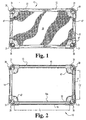
- FIG. 1 is a top plan view of a cot assembly according to a preferred embodiment of the present invention.
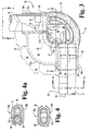
- FIG. 2 is a top plan view of the cot frame of the embodiment of FIG. 1.
- FIG. 3 is a partial top plan view of one corner of the cot assembly of FIG. 1.
- FIG. 4 is a cross-sectional view of the comer connector of FIG. 3 taken along lines 4-4 of FIG. 3.
- FIG. 4a is a cross-sectional view of the comer connector of FIG. 3 taken
along
lines 4a-4a of FIG. 3. - FIG. 5 is an elevational view of an corner connector comprising a portion of the cot assembly of FIG. 1.
- FIG. 6 is a section of the comer connector of FIG. 4 taken through line 6-6.
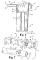
- FIG. 7 is an exploded perspective view of a ratchet mechanism according to another aspect of the present invention.
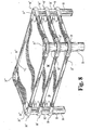
- FIG. 8 is a perspective view of three cot assemblies of FIG. 1 nestably stacked one upon another.
-
- For the purposes of promoting an understanding of the principles of the invention, reference will now be made to the embodiment illustrated in the drawings and specific language will be used to describe the same. It will nevertheless be understood that no limitation of the invention is thereby intended, such alterations and further modifications in the illustrated device, and such further applications of the principles of the invention as illustrated therein being contemplated as would normally occur to one skilled in the art to which the invention relates.
- The present invention provides a cot assembly that has several advantageous design features not available in the prior art. Importantly, the cot includes a bedding material that spans the entire interior of the cot frame without any gaps being present between the bedding material and the frame. Also, this fully spanning bedding material is capable of being adjusted after the cot has been assembled to adjust the tightness of he material. Further, these features are provided in a cot assembly that is simple and reliable in construction, is easily assembled and later adjusted for tautness, and does not have exposed parts that may pose a problem for the user, particularly for children.
- The present invention is directed to a cot assembly that has a frame which forms a perimeter which defines an interior area in which a person lying on the cot is supported. Bedding material is connected with and extends between the members of the frame in the interior area such that no openings are formed in the interior area between the bedding material and the frame. In another form of the present invention, a
ratchet mechanism 11 is provided to position and maintainbedding material 20 in a taut condition. - Referring in particular to FIGS. 1-2, there is shown a
cot 10 having aframe 12 including a number of elongated rods 14-17. A corresponding number ofcorner connectors 30 are connected to respective ends of the rods 14-17 to form theframe 12. It is contemplated herein thatframe 12 may have a plan view forming any one of a number of polygonal shapes, such as a rectangle, square, pentagon, a combination of straight and curved members, or only curved members, etc. The frame is shown as consisting of rods which generally comprises hollow tubes either in round or non-round cross-section. As used herein, the term "rods" is used more broadly as encompassing any elongated member which can be coupled together to form a frame for supporting the bedding material used in a typical cot. It will therefore be appreciated that such rods may comprise any of a wide variety of material and shapes depending on the intended use of the cot. - Bedding
material 20 is connected with the rods 14-17 of theframe 12 and extends therebetween in the interior area offrame 12 to create a support surface for a person lying on the cot. Thebedding material 20 extends horizontally substantially parallel to the floor or ground. Beddingmaterial 20 andframe 12 are supported above the floor or ground by pedestals 33 (FIG. 5) extending downwardly from thecorner connectors 30 to suspend the bedding surface above an underlying support surface. Thebedding material 20 is made from a material of suitable strength and comfort to support a person lying on thecot 10, the selection of which is within the ordinary skill in the art. Bedding material is typically a relatively thin, flexible and compliant material, preferably sheet-like in shape. The material may be any suitable one, e.g., a natural or synthetic sheeting, fabric, mat, webbing or the like. - As previously described, the
bedding material 20 andframe 12 are assembled such that there are no openings formed between the frame and the bedding material in the interior area of the frame. The bedding material is attached to the frame, and any free portions of the bedding material will at least extend to or overlap with the frame. It will be appreciated that there are numerous ways of attachment to accomplish this gap free construction. Shown herein is a preferred embodiment for providing the gap free condition. As used herein, the term "gap free" or similar terms are used to describe the fact that the bedding material fills the interior of the area defined by the frame perimeter when viewed in the plan view. Moreover, a preferred feature of the present invention is the provision of a gap free condition that further provides for adjusting the tautness of the bedding material, as described hereafter. - The
cot frame 12 is illustrated in FIG. 2 and without the bedding material shown to better depict the details of theframe 12 and its components. Preferably, the cot assembly includesside rods rods Frame 12 also includes a second pair of spacedend rods - The side and end rods comprise a profile that provides a preferred support structure and shape for the cot. The rods 14-16 are shown as having a cross section with flat top and bottom surfaces connecting rounded sides in a "race track" shape, although other shapes could readily be used, including round, square, oval and many others. The configuration shown has several advantages. The upper support surface is wider than would be provided for a round rod of comparable diameter. The non-round cross section also prevents "racking" when the cots are subjected to a longitudinal twisting force. Racking can occur when the round members of a frame rotate relative the comer connectors, thereby skewing the otherwise flat shape of the cot, and causing a corner of the cot to be spaced from the underlying cot when they are stacked or put on the floor. This can lead to instability of a stack of cots. For the present invention, since non-round rods cannot rotate relative to the corner connectors, the potential for racking is avoided.
- The cot preferably includes at least one end member that enables the user to adjust the tautness of the bedding material. In the embodiment of FIG. 2, this is accomplished by means of the
rod 17 and a complementary rotational adjustment system. As shown, a mechanism is provided which operates in cooperation withrod 17 to allow for selective rotation ofrod 17 in one direction to tighten the bedding material. In particular, this end of the cot includes a combination ofrod 17 and anadjacent support member 50. As seen in FIG. 4a,rod 17 is round andsupport member 50 is shaped and positioned complementary withrod 17 so the combination of the two provides an outer cross section profile that is the same as that for the rods 14-16. This enables the rods and corner connectors to be interchangeables. - The assembly of the cot frame is straightforward. The rods can be readily connected with the corner connectors in any of a variety of ways. As will be apparent from the later description of the corner connectors and associated components, the rods may be attached to the corner connectors by press fit, gluing, mechanical fastening or any other means, with a simple mechanical fit of the components being preferred to simplify assembly and facilitate disassembly if that becomes desired. Further, the combination of the bedding material with the frame assembly will provide another means for maintaining the frame members in the assembled condition. It is a feature of the present invention that no screws, pins or other fasteners are required to hold the cot together, and therefore such fasteners are not exposed to the user, and cannot be removed by the user.
- Bedding
material 20 is attached to the cot frame. Such attachment may take many forms. In the preferred embodiment, the bedding material includes a plurality ofsleeves 22, each configured to be received over any of the non-adjusting rods, such as rods 14-16. In an alternate method of attachment,bedding material 20 extends around the exterior portion of a rod and is connected to the rod by suitable fasteners, the selection of which is within the ordinary skill in the art. In view of the intended rotation ofrod 17 for adjustment of tautness, this method of attachment is appropriate for such an adjusting-type rod. In any event,bedding material 20 is sized such that when the members offrame 12 andcorner connectors 30 are assembled, as described above and shown in FIG. 1, thebedding material 20 extends between the members of theframe 12 and fills the interior area offrame 12. - Each of the
corner connectors 30 includes ahousing 32 having a top portion 37 (FIG. 5).Housing 32 has afirst coupling portion 34a and asecond coupling portion 34b. Couplingportions rod 17 andsupport member 50. -
First coupling portion 34a includes afirst sleeve 35a, andsecond coupling portion 34b includes asecond sleeve 35b. Each of the first andsecond sleeves frame 12. Each of thecoupling portions first connector 38 and an adjacentsecond connector 39 extending outwardly into thesleeves First connector 38 andsecond connector 39 connect the rod members and assemblies offrame 12 withcorner connector 30. - Preferably, the
first connector 38 is circular in cross-section, as shown in FIG. 5, and sized so that a hollow end ofrod 17 can be connected to theconnector 38 to be rotatable about the connector. Thesecond connector 39 is semi-circular in cross section and sized to receive a hollow end ofsupport member 50 in non-rotational engagement. The combined outer perimeter of the adjacent first andsecond connectors rod 14 tocomer connector 30. The present invention also contemplates other cross-sectional shapes for rods 14-16 and the corresponding first andsecond connectors - More particularly, the preferred embodiment shown in the drawings provides a coupling system which advantageously can be combined either with the non-adjusting rods such as 14-16 or the adjusting
rod 17 and its associated adjustment mechanism. Referring to FIG. 4, an elevational view looking toward thecoupling member 34a shows that the rods, such as 14, is received within thesleeve 35a ofcoupling member 34a and about theconnectors same connectors rod 17 andsupport member 50, respectively. - Other cross sections for
support member 50 andsecond connector 39 are also contemplated, so long as there is engagement therebetween preventing rotation of thesupport member 50. In one alternate embodiment, the first andsecond connectors rod 14 thereover. Such an embodiment would be particularly desirable in a cot assembly that only includesrods 14. Other cross-sections forrod 14 andconnectors -
Pedestal 33 is defined by anouter wall surface 42, which tapers to a reduced cross-section as it extends downwardly to bottom 43.Pedestal 33 has a height from the floor to thecoupling portions bedding material 20 above the ground or floor.Housing 32 also definespocket 31 positioned between thecoupling portions Pocket 31 includes substantially verticalinner walls pocket 31.Inner walls inner wall 31c as each extends downwardly towards apedestal support surface 40 positioned withinpocket 31.Inner wall portion 31c also tapers slightly inwardly towardsinner walls bottom 43 ofpedestal 33. A plurality ofstruts 44 extend between bottom 43 andsupport surface 40, providing stability and strength to thepedestal 33. - The
inner walls pocket 31 in a shape to receive the pedestal of a second cot with theouter surface 42 of the received pedestal in close or abutting contact with the inner walls ofpocket 31. Preferably, the interface between the inner walls ofpocket 31 and the outer surface of the received pedestal is such that a plurality of cots may be easily stacked and unstacked with minimum exertion or effort. Further, the fit is desirably close enough that it provides stability to a stack of cots. -
Bottom 43 defines at least one opening 43a communicating with a hollow interior ofpocket 31. Openings 43a provide a passageway for air as a pedestal is inserted into or removed from thepocket 31, thus facilitating the stacking and unstacking of cots. Pocket bottom 40 similarly includes apertures which facilitate the passage of air when cots are being stacked or unstacked. - A
rounded overhang 41 extends around the entry to pocket 31adjacent top 37.Overhang 41 extends between thecoupling portions Overhang 41 also stiffens the overall structure ofhousing 32, supports thepocket 31 and facilitates efficient stacking of cots by providing an entry portion for the pedestal that is free from rough or sharp edges. - The gap free effect accomplished by the present invention may be obtained in a variety of ways. The bedding material is secured to the cot frame in a position that has the bedding material extending at least to the frame perimeter. Preferably, the bedding material extends at least to an overlap with the frame, and in suitable locations, such as along the side and end rods, the material is directly affixed to the frame.
- In the preferred embodiment shown,
corner connector 30 includes inwardly projectingportion 47 extending into the interior area offrame 12. Beddingmaterial 20 is positioned at least in abutting engagement with anedge 47a of inwardly projectingportion 47 so that no gaps are formed in the interior area offrame 12 betweenbedding material 20 and theframe 12. In a most preferred form,bedding material 20 at least overlaps the inwardly projectingportion 47 or is fastened thereto. In a preferred embodiment, inwardly projectingportion 47 includestop flange 48 andbottom flange 49 spanning betweencoupling portions pocket 31 in the interior of theframe 12. Preferably, thebottom flange 49 projects inwardly a distance slightly less thantop flange 48. Aslot 46 is defined between thetop flange 48 andbottom flange 49, theslot 46 communicating withsleeve 35a andsleeve 35b through apertures, such as 46a (FIG. 5). When thecot 10 is assembled, thebedding material 20 has an outer edge 26 (FIG. 3) that is received withinslot 46 and extends fromfirst sleeve 35a tosecond sleeve 35b within theslot 46. Thus, the risk of injury or damage to thecot 10 due to openings or gaps betweenframe 12 andbedding material 20 is eliminated. - The present invention contemplates other configurations for inwardly projecting
portion 47. For example, although illustrated as having a shape that resembles a quarter-circle in plan view, other shapes forflanges single flange bedding material 20. However, it is preferred to provide both a top and bottom flange with a slot therebetween. Thetop flange 48 shields and protects theedge 26 ofbedding material 20, andbottom flange 49 provides additional support along the bottom ofbedding material 20 where it spans between the coupling portions. Thebedding material 20 may also be fastened to one or both of theflanges adjacent edge 26, thus providing further support. - As best shown in FIG. 5, the
top flange 48 is positioned somewhat below top 37 ofhousing 32.Slot 46 is preferably aligned with the center ofsleeves frame 12, thus providing a smooth transition for thebedding material 20 as it extends between adjacent members of theframe 12. - The present invention provides a novel method for tightening the bedding material on a cot. It will be appreciated that the tightening of the bedding material may be accomplished with a few as one such means, or with as many as four of them. In certain embodiments, a single adjustment means is sufficient, with it being placed on the end or side, depending on the design of the cot, composition of the bedding material and other such considerations. In an alternate approach, a pair of adjustment means are provided, one being along a side and the other being along an end.
- An exemplary embodiment for a tightening system is shown in FIG. 7, which depicts an exploded view of a
ratchet mechanism 11 that may be incorporated intocot assembly 10. A portion ofsupport member 50 is illustrated along with the corresponding portion ofrod 17. It should be understood thatframe 12 may be provided withoutratchet mechanism 11. -
Support member 50 is shown as including anend piece 52 removably connected with an extended connectingmember 51.End piece 52 includes abody 54 and aninsertion end 56 having aninterior wall 60 defining acavity 61. Asecond connector 39 is received withincavity 61 to connect with theend piece 52.End piece 52 further has a reduced-size engagement end 58 adapted to be slidingly and non-rotatably received within thecavity 78 formed atend 74 of connectingmember 51. The connectingmember 51 has abody 72 with a length sized to extend fromend piece 52 to asecond corner connector 30. At this opposite end, connectingmember 51 is either directly connected with asecond connector 39, or a mirror-image end piece 52 and associated ratchet type mechanism could be employed. -
Assembled support member 50 has aconcave surface 53 extending along its length fornestably positioning rod 17 therealong.End piece 52 has anaperture 62 formed inconcave surface 53 that communicates withcavity 61. Integrally formed with and engaged atedge 63 of theaperture 62 is atang 64 that projects into theaperture 62.Tang 64 substantially occupies theaperture 62; however, it is deflectable inwardly with respect to surface 53 ofend piece 52 alongedge 63.Tang 64 has a wedge-shapedprojection 66 that includes atop edge 67 and slopedsurface 68. Theprojection 66 extends outwardly fromconcave surface 53 towards theadjacent rod 17. Thetang 64 deflects intocavity 61 when pressure is applied in the direction of arrow P. -
Rod 17 has a cylindrical outer wall and defines ahollow interior 15.Rod 17 has a plurality ofholes 18 along its length to receive fasteners (not shown) therethrough. The fasteners extend through thebedding material 20 positioned around therod 17 and prevent relative movement therebetween. The fasteners may be rivets, screws, bolts, or the like. In a preferred approach, hooks are welded into the bedding fabric and the hooks are in turn received within theholes 18. Another preferred approach is to use ultra frequency welding to attach tabs onto the fabric for reception by the holes. Alternatively, other attachment means could be used, such as gluing, taping, clamping, etc. Located at the end ofrod 17 areseveral slots 19 communicating withhollow interior 15. Theslots 19 are positioned such that they align with and are sized to receiveprojection 66 ofend piece 52 when thesupport member 50 androd 17 are engaged tocomer connector 30. -
Comer connector 30 defines atool opening 29 formed in the bottom portion of the wall ofsleeve 34b, as shown in FIG. 5. Thetool opening 29 is to be located whererod 17 is connected withcorner connector 30.Tool opening 29 is positioned adjacent to but beyond the end offirst connector 38 so that there is no interference between thefirst connector 38 and a tool inserted throughopening 29. Whiletool opening 29 is illustrated in FIG. 5 onsleeve 34b, it is also contemplated herein thattool opening 29 could be positioned onsleeve 34a, or that bothfirst sleeve 34a andsecond sleeve 34b are provided withtool openings 29. Whenframe 12 is assembled, theslots 19 are aligned with tool opening 29 formed in the bottom ofsleeve 34b such that a tool may be inserted through theopening 29 and into one of theslots 19. -
Ratchet mechanism 11 functions as follows. Thetop surface 67 ofprojection 66 engages therod 17 at an edge of one of the plurality ofslots 19 to prevent rotation of therod 17 about axis 1 in the direction indicated by the arrow S. If therod 17 is allowed to rotate in the direction of arrow S, thebedding material 20 will sag.Ratchet assembly 11 allows bedding 20 to be made taut and remove any sag that may be present by rotating therod 17 about axis 1 in the direction indicated by arrow R. Therod 17 may be rotated by extending a tool, such as a screwdriver or other elongated member, throughopening 29 and into one of theslots 19. The bedding material is made taut by rotating therod 17 in the direction R. The wedged shapedprojection 66 flexes intocavity 61 as the bottom portion of the projection is rotated past the previously engagedslot 19. The edge of the previously engagedslot 19 applies pressure along the sloped surface ofprojection 66, gradually flexing theprojection 66 further intocavity 61. When therod 17 is rotated so that the edge of anadjacent slot 19 moves pasttop surface 67, theprojection 66 returns to its at rest position and is received within theadjacent slot 19. Theadjacent slot 19 supports therod 17 as described above and resists rotation in the direction of arrow S. The above steps may be repeated as necessary to achieve the desired rotation ofrod 17 and consequent tensioning ofbedding material 20. - The tensioning mechanism shown in the preferred embodiment is a simple, reliable system that is totally concealed. No fasteners or other devices are required that project from the cot assembly. At the same time, the mechanism can be easily accessed for purposes of adjustment, and only a simple tool such as a screw driver is required.
- Referring to FIG. 8, each of the
corner connectors 30 includes ahousing 32 defining apocket 31 that allows a plurality ofcots 10 to be nestably stacked one upon another. For example, the pocket of one cot is sized and configured to slidably and removably receive a pedestal of the corner connector of a second cot. As an example, FIG. 8 illustrates threecots corner connectors pedestal cot 10" are received within corresponding ones of thepockets 31 ofcot 10 and the pockets 31' of cot 10', respectively. Thus, the stacked height ofcots - Variations in the configurations of the adjustment mechanisms are contemplated and are well within the skill in the art. While
support member 50 has been illustrated as being formed byend piece 52 and connectingmember 51, it is contemplated that connectingmember 51 may be integrally formed withend piece 52 to formsupport member 50. However, the use of suchseparate pieces ratchet mechanism 11 are also contemplated herein as would occur to one of ordinary skill in the art. - Further, it will be appreciated that other means to hold the
rod 17 against rotation could similarly be used. The design shown herein has certain advantages, however, For example, the design results in a ratchet mechanism that has an outer profile that matches that for the alternative, non-adjusting rods. Therefore, the parts are readily interchanged to produce cots with varying numbers and position of adjustment devices. Moreover, the adjustment rod assembly obtains the same broad upper surface, and the associated advantages described earlier, even though the rotatingrod 17 is of much lower diameter. These and other advantages are achieved with the preferred embodiment, but alternate designs are contemplated, particularly where some or all of these advantages are not considered to be significant for a given application. - While the invention has been illustrated and described in detail in the drawings and foregoing description, the same is to be considered as illustrative and not restrictive in character, it being understood that only the preferred embodiment has been shown and described.
Claims (34)
- A cot assembly which comprises:characterised in that said bedding material (20) completely filling the interior area defined by said frame (12), whereby there are no gaps between said bedding material (20) and said frame (12) in which a part of a person's body may be received.a frame (12) forming a perimeter and defining an interior area within the perimeter;means (33) for supporting said frame (12) above an external support surface; andbedding material (20) secured to said frame (12);
- The cot assembly of claim 1 and which further includes tensioning means (11) for varying the tension of said bedding material (20).
- The cot assembly of claim 2 in which said frame (12) comprises several elongated rods (14-17) interconnecting with several comer connectors (30) to form a rectangular perimeter.
- The cot assembly of claim 3 in which said tensioning means (11) includes means for rotating at least one of the rods (17).
- The cot assembly of claim 1 in which said frame (12) comprises several elongated rods (14-17) interconnecting with several comer connectors (30) to form a rectangular perimeter.
- The cot assembly of claim 5 in which said bedding material (20) is secured to only the rods (14-17) of said frame (12).
- The cot assembly of claim 5 in which said bedding material (20) is secured to the rods (14-17) and the corner connectors (30) of said frame (12).
- The cot assembly of claim 5 in which said supporting means comprises pedestals (33) attached to and extending downwardly from the comer connectors (30) of said frame (12).
- The cot assembly of claim 5 in which each of the corner connectors (30) includes an inwardly projecting portion (47) extending into the interior area of said frame (12), said bedding material (20) extending at least to said inwardly projecting portions (47) such that no openings are formed in the interior area of said frame (12).
- The cot assembly of claim 9, wherein said bedding material (20) overlaps the inwardly projecting portions (47).
- The cot assembly of claim 9 in which said bedding material (20) is secured to the inwardly projecting portions (47).
- The cot assembly of claim 9 in which each of the corner connectors (30) includes a pair of the rods (14-17) being connected therewith, each comer connector (30) including a housing (32), a first end portion (34a) extending from the housing (32) along a portion of the length of one of the rods (14-17) connected therewith, and a second end portion (34b) extending from the housing (32) along a portion of the length of the other of the rods (14-17) connected therewith.
- The cot assembly of claim 12 in which said supporting means comprises pedestals (33) attached to and extending downwardly from the comer connectors (30) of said frame (12).
- The cot assembly of claim 13 in which each housing (32) includes a pocket (31) configured for nestably receiving a pedestal (33) of a second cot assembly.
- The cot assembly of claim 12 wherein each of the inwardly projecting portions (47) includes a top flange (48) and a bottom flange (49) extending into the interior area of said frame (12) between the end portions (34a, 34b), the top and bottom flanges defining a slot (46) therebetween, said bedding material (20) being received within the slot (46).
- The cot assembly of claim 15 wherein the first end portion (34a) and the second end portion (34b) each define a hollow sleeve (35a, 35b), the slot (46) communicating with the hollow sleeves (35a, 35b), said bedding material (20) extending between the sleeves (35a, 35b).
- The cot assembly of claim 15 wherein the top flange (48) projects further into the interior than the bottom flange (49).
- A cot assembly according to claim 1, wherein said frame includes a number of elongated rods (14-17) and a number of comer connectors (30) connecting with the ends of a pair of associated rods (14-17) such that said frame (12) forms a polygon shape, each of the corner connectors (30) including a pedestal (33) extending downwardly therefrom to engage a support surface, wherein said bedding material (20) extends between the rods (14-17) in the interior area of said frame (12), the comer connectors (30) includes means (46) for receiving said bedding material (20) so that no openings are formed in the interior area of said frame (12) between said bedding material (20) and the comer connectors (30).
- The cot assembly of claim 18 wherein said frame (12) includes a support member (50) adjacent to and extending along the length of at least one of the rods (17), the support member (50) having ends non-rotatably engaged to a corresponding one of a pair of the corner connectors (30).
- The cot assembly of claim 19, wherein each of the corner connectors (30) includes a housing (32), the housing (32) including a first end portion (34a) extending along a portion of the length of one of the rods (14-17) connected therewith, the housing further including a second end portion (34b) extending along a portion of the length of the other of the rods (14-17) connected therewith.
- The cot assembly of claim 20, wherein the support member (50) includes a ratchet mechanism (62,64,66) and the at least one rod (17) defines a plurality of slots (19) adjacent the ratchet mechanism (62,64,66), the ratchet mechanism being engageable with one of the slots (19) to prevent rotation of the at least one rod (17) in a first direction while allowing the at least one rod (17) to be rotated in an opposite second direction to engage another of the slots (19) upon application of a rotational force about the longitudinal axis of the at least one rod (17).
- The cot assembly of claim 21, wherein the ratchet mechanism includes a deflectable wedge-shaped portion (66) projecting into one of the slots (19), the wedge shaped portion (66) having a top surface (67) engaging an edge of the slot (19) and a sloped surface (68) extending downwardly from the top surface (67) to deflect the wedge-shaped portion (66) away from the at least one rod (17) as the rod (17) rotates in response to the rotational force.
- The cot assembly of claim 21, wherein the support member (50) defines a concave surface (53) adjacent to and extending along the length of the rod (17), the ratchet mechanism (62,64,66) being positioned on the concave surface (53).
- The cot assembly of claim 21, wherein at least one of the end portions receiving the at least one rod defines a tool opening (29) aligned with the plurality of slots for receiving a tool engageable with one of the slots for applying the rotational force.
- The cot assembly of claim 21, wherein each of the pair of corner connectors (30) includes a first connector (38) and a second connector (39) projecting from said housing (32) into the coupling portion for receiving the at least one rod (17) and the support member (50), the first connector (38) rotatably connecting the at least one rod (17) to the corner connector (30) and the second connector (39) non-rotatably connecting the support member (50) to the corner connector (30).
- The cot assembly of claim 25, wherein the at least one rod (17) has a circular cross section and the support member (50) has a semi-circular cross-section.
- The cot assembly of claim 26, where the rods (14-16) other than the at least one rod (17) have a race-track shaped cross-section.
- The cot assembly according to claim 1, wherein said frame (12) includes:a number of elongated rods (14-17);a number of comer connectors (30), each of the corner connectors (30) connected with one end of each of a pair of the rods (14-17) so that said frame (12) forms a polygon shape;a support member (50) adjacent to and extending along at least one of the number of rods (17), the support member (50) having opposite ends non-rotatably engaged to a corresponding pair of the comer connectors (30), the at least one rod (17) having a plurality of slots (19) adjacent one of the opposite ends (52) of the support member (50);a pedestal (33) extending downwardly from the corner connector (30) to engage the floor;said bedding material (20) being engaged to and extending between the number of rods (14-17) in the interior area of said frame (12); andmeans (11) associated with said frame (12) for positioning and maintaining said bedding material (20) in a taut condition, said means (11) for positioning and maintaining said bedding material (20) in a taut condition including a ratchet mechanism (62,64,66) on the support member (50) engageable to one of the slots (19) of the at least one rod (17).
- The cot assembly of claim 28, wherein the ratchet mechanism (62,64,66) prevents rotation of the rod (17) in a first direction and allows the rod (17) to be rotated in an opposite second direction to engage another of the slots (19) upon application of a rotational force about the longitudinal axis of the rod (17).
- The cot assembly of claim 29, wherein the ratchet mechanism includes a deflectable wedge-shaped portion (66) projecting into one of the slots, the wedge-shaped portion having a top surface (67) engaging an edge of the slot (19) and a sloped surface (68) extending downwardly from the top surface (67) that deflects the wedge-shaped portion (66) away from the rod (17) as the rod (17) rotates in response to the rotational force.
- The cot assembly of claim 30, wherein the corner connector (30) engaged to the at least one rod (17) end defines a tool opening (29) aligned with the plurality of the slots (19) for receiving a tool engageable with one of the slots (19) to apply the rotational force.
- The cot assembly of claim 28, wherein the support member (50) defines a concave surface (53) adjacent to and extending along the length of the at least one rod (17), the ratchet mechanism (62,64,66) positioned on the concave surface (53).
- The cot assembly of claim 28, wherein the support member (50) includes an end piece (52) connecting with one of the pair of corner connectors (30) at one end and engaged at another end to a connecting member, the connecting member (51) extending from the end piece (52) and connecting with the other of the pair of corner connectors (30).
- The cot assembly of claim 33, wherein the ratchet mechanism (62,64,66) is on the end piece (52).
Applications Claiming Priority (2)
| Application Number | Priority Date | Filing Date | Title |
|---|---|---|---|
| US571132 | 2000-05-15 | ||
| US09/571,132 US6513178B1 (en) | 2000-05-15 | 2000-05-15 | Cot assembly |
Publications (3)
| Publication Number | Publication Date |
|---|---|
| EP1155642A2 EP1155642A2 (en) | 2001-11-21 |
| EP1155642A3 EP1155642A3 (en) | 2002-07-17 |
| EP1155642B1 true EP1155642B1 (en) | 2005-05-04 |
Family
ID=24282441
Family Applications (1)
| Application Number | Title | Priority Date | Filing Date |
|---|---|---|---|
| EP00309057A Expired - Lifetime EP1155642B1 (en) | 2000-05-15 | 2000-10-16 | Cot assembly |
Country Status (3)
| Country | Link |
|---|---|
| US (1) | US6513178B1 (en) |
| EP (1) | EP1155642B1 (en) |
| DE (1) | DE60019900T2 (en) |
Families Citing this family (19)
| Publication number | Priority date | Publication date | Assignee | Title |
|---|---|---|---|---|
| FR2832043B1 (en) * | 2001-11-14 | 2005-06-10 | Wesco | STACKABLE SLEEVE AND ANGLE MEMBER FOR SUCH A SLEEVE |
| US20040237899A1 (en) * | 2003-05-12 | 2004-12-02 | Bryan Fung | Chew-resistant pet bed |
| CA2435453C (en) * | 2003-07-16 | 2008-08-05 | Robert James Hunter | Conversion kit for turning a cross-legged folding cot into a tiered cot |
| US7260856B2 (en) * | 2003-08-20 | 2007-08-28 | Angeles Corporation | Stackable cot assembly |
| US20050166317A1 (en) * | 2004-02-02 | 2005-08-04 | Kelly Ray G. | Method of manufacture and products using fabric in injection molding |
| US7086100B1 (en) * | 2005-05-11 | 2006-08-08 | Lo Feng-Jung | Joining assembly for child's bed |
| US20070062456A1 (en) * | 2005-09-16 | 2007-03-22 | Laura Pace | Animal bed |
| US8769746B2 (en) | 2006-08-07 | 2014-07-08 | Airnettress Ltd. | Support surface assembly and tensioning method for a sleeping person |
| US7559290B2 (en) * | 2006-09-07 | 2009-07-14 | Paula Lee West | Pet bed overlay, system, and retrofit kit |
| US8739333B2 (en) | 2010-04-05 | 2014-06-03 | Central City Concern | Bedbug infestation-resistant bed |
| US8919284B2 (en) * | 2012-04-20 | 2014-12-30 | Starmark Pet Products, Inc. | Animal bed |
| US9398815B2 (en) | 2014-07-21 | 2016-07-26 | Foundations Worldwide, Inc. | Cot |
| USD747116S1 (en) | 2014-07-21 | 2016-01-12 | Foundations Worldwide, Inc. | Cot |
| USD787873S1 (en) * | 2015-06-18 | 2017-05-30 | ECR4Kids, L.P. | Corner leg for cot |
| ES1168583Y (en) | 2016-10-14 | 2017-01-24 | Rosa Salvador Jose Poveda | Bed or hammock |
| US10898006B2 (en) * | 2017-08-03 | 2021-01-26 | The Pet Cot Company | Cot and corner connector therefor |
| CN111265054A (en) * | 2020-03-18 | 2020-06-12 | 周福亨 | Physiotherapy and sleep-aid sports device |
| CN112545244A (en) * | 2020-12-01 | 2021-03-26 | 上海金字塔睡眠科技有限公司 | Physiotherapy and sleep-aid power device |
| CN112998473A (en) * | 2021-02-25 | 2021-06-22 | 张志凤 | Intelligent manufacturing bed leg structure with bed board protection and deviation prevention functions |
Family Cites Families (13)
| Publication number | Priority date | Publication date | Assignee | Title |
|---|---|---|---|---|
| US1566574A (en) * | 1925-12-22 | Knockdown camp bed | ||
| US1820285A (en) * | 1930-11-06 | 1931-08-25 | Mills Frank Louis | Bed |
| CH261936A (en) * | 1946-01-23 | 1949-06-15 | Peyron Georges | Folding cabinet. |
| US2924830A (en) | 1953-07-02 | 1960-02-16 | Long Ruth Nash De | Nesting furniture structure |
| US2871489A (en) | 1956-05-29 | 1959-02-03 | Fed Premium Service Inc | Bed construction |
| GB1115511A (en) | 1964-12-23 | 1968-05-29 | John Guythar Bradford | Improvements relating to collapsible supporting structures |
| US3426367A (en) | 1965-12-21 | 1969-02-11 | John G Bradford | Collapsible supporting structures |
| US3710405A (en) | 1971-10-27 | 1973-01-16 | Sealy | Bed carrying frame |
| US3886606A (en) | 1973-05-29 | 1975-06-03 | John Guythar Bradford | Foldable casualty carrier |
| US4958390A (en) | 1988-11-04 | 1990-09-25 | Holbrook-Patterson, Inc. | Rest cot assembly |
| US5003649A (en) | 1990-01-05 | 1991-04-02 | Angeles Nursery Toys, Inc. | Nestable cot and end connector therefor |
| US5960739A (en) * | 1997-10-27 | 1999-10-05 | Scandinavian Computer Furniture, Inc. | Bed for animals |
| US5992348A (en) * | 1998-03-11 | 1999-11-30 | Harding; Michael S. | Chew-proof animal bed |
-
2000
- 2000-05-15 US US09/571,132 patent/US6513178B1/en not_active Expired - Lifetime
- 2000-10-16 EP EP00309057A patent/EP1155642B1/en not_active Expired - Lifetime
- 2000-10-16 DE DE60019900T patent/DE60019900T2/en not_active Expired - Fee Related
Also Published As
| Publication number | Publication date |
|---|---|
| EP1155642A3 (en) | 2002-07-17 |
| DE60019900D1 (en) | 2005-06-09 |
| EP1155642A2 (en) | 2001-11-21 |
| US6513178B1 (en) | 2003-02-04 |
| DE60019900T2 (en) | 2006-02-23 |
Similar Documents
| Publication | Publication Date | Title |
|---|---|---|
| EP1155642B1 (en) | Cot assembly | |
| US6430762B1 (en) | Baby playpen-bassinet combination | |
| US5987822A (en) | Inflatable tent | |
| CA2254486C (en) | Trampoline with elastic frame attachment system | |
| US5893238A (en) | Inflatable tent construction | |
| WO1999030593A1 (en) | Bed rail center support system | |
| US6564400B2 (en) | Continuous tube cot assembly | |
| US20020166170A1 (en) | Playard having corner panels | |
| US4270748A (en) | Modularized slide | |
| CA2238684A1 (en) | Unitary body bedding foundation | |
| US7458116B2 (en) | Stackable cot assembly | |
| US20230042530A1 (en) | Headboard | |
| EP0436460B1 (en) | Nestable cot and end connector therefor | |
| US20010013145A1 (en) | Portable cot apparatus | |
| KR200445448Y1 (en) | Leg structure for a table | |
| US20050071919A1 (en) | Corrugated cardboard crib | |
| WO1994025296A1 (en) | Mounting system for artist's material and the like | |
| GB2295539A (en) | Bedstead structure | |
| KR200186798Y1 (en) | A folding screen | |
| EP1219209B1 (en) | Leg for stackable bed | |
| US6487815B2 (en) | Adjustable protective platform for supporting potted plants | |
| AU675272B2 (en) | Table means | |
| JPH0727872Y2 (en) | Portable macula and chair | |
| JPH10248679A (en) | Bed seat device for simple bed | |
| GB2339684A (en) | Swinging cradle |
Legal Events
| Date | Code | Title | Description |
|---|---|---|---|
| PUAI | Public reference made under article 153(3) epc to a published international application that has entered the european phase |
Free format text: ORIGINAL CODE: 0009012 |
|
| AK | Designated contracting states |
Kind code of ref document: A2 Designated state(s): AT BE CH CY DE DK ES FI FR GB GR IE IT LI LU MC NL PT SE |
|
| AX | Request for extension of the european patent |
Free format text: AL;LT;LV;MK;RO;SI |
|
| PUAL | Search report despatched |
Free format text: ORIGINAL CODE: 0009013 |
|
| AK | Designated contracting states |
Kind code of ref document: A3 Designated state(s): AT BE CH CY DE DK ES FI FR GB GR IE IT LI LU MC NL PT SE |
|
| AX | Request for extension of the european patent |
Free format text: AL;LT;LV;MK;RO;SI |
|
| 17P | Request for examination filed |
Effective date: 20030116 |
|
| AKX | Designation fees paid |
Designated state(s): DE FR GB |
|
| 17Q | First examination report despatched |
Effective date: 20031120 |
|
| RAP1 | Party data changed (applicant data changed or rights of an application transferred) |
Owner name: ANGELES GROUP, LLC |
|
| GRAP | Despatch of communication of intention to grant a patent |
Free format text: ORIGINAL CODE: EPIDOSNIGR1 |
|
| GRAS | Grant fee paid |
Free format text: ORIGINAL CODE: EPIDOSNIGR3 |
|
| GRAA | (expected) grant |
Free format text: ORIGINAL CODE: 0009210 |
|
| RAP1 | Party data changed (applicant data changed or rights of an application transferred) |
Owner name: ANGELES GROUP, INC. |
|
| RAP1 | Party data changed (applicant data changed or rights of an application transferred) |
Owner name: ANGELES GROUP, LLC |
|
| AK | Designated contracting states |
Kind code of ref document: B1 Designated state(s): DE FR GB |
|
| REG | Reference to a national code |
Ref country code: GB Ref legal event code: FG4D |
|
| REG | Reference to a national code |
Ref country code: IE Ref legal event code: FG4D |
|
| REF | Corresponds to: |
Ref document number: 60019900 Country of ref document: DE Date of ref document: 20050609 Kind code of ref document: P |
|
| PLBE | No opposition filed within time limit |
Free format text: ORIGINAL CODE: 0009261 |
|
| STAA | Information on the status of an ep patent application or granted ep patent |
Free format text: STATUS: NO OPPOSITION FILED WITHIN TIME LIMIT |
|
| ET | Fr: translation filed | ||
| 26N | No opposition filed |
Effective date: 20060207 |
|
| PGFP | Annual fee paid to national office [announced via postgrant information from national office to epo] |
Ref country code: DE Payment date: 20071011 Year of fee payment: 8 |
|
| PGFP | Annual fee paid to national office [announced via postgrant information from national office to epo] |
Ref country code: FR Payment date: 20071009 Year of fee payment: 8 Ref country code: GB Payment date: 20071010 Year of fee payment: 8 |
|
| GBPC | Gb: european patent ceased through non-payment of renewal fee |
Effective date: 20081016 |
|
| REG | Reference to a national code |
Ref country code: FR Ref legal event code: ST Effective date: 20090630 |
|
| PG25 | Lapsed in a contracting state [announced via postgrant information from national office to epo] |
Ref country code: DE Free format text: LAPSE BECAUSE OF NON-PAYMENT OF DUE FEES Effective date: 20090501 |
|
| PG25 | Lapsed in a contracting state [announced via postgrant information from national office to epo] |
Ref country code: FR Free format text: LAPSE BECAUSE OF NON-PAYMENT OF DUE FEES Effective date: 20081031 |
|
| PG25 | Lapsed in a contracting state [announced via postgrant information from national office to epo] |
Ref country code: GB Free format text: LAPSE BECAUSE OF NON-PAYMENT OF DUE FEES Effective date: 20081016 |