US6487815B2 - Adjustable protective platform for supporting potted plants - Google Patents
Adjustable protective platform for supporting potted plants Download PDFInfo
- Publication number
- US6487815B2 US6487815B2 US09/754,436 US75443601A US6487815B2 US 6487815 B2 US6487815 B2 US 6487815B2 US 75443601 A US75443601 A US 75443601A US 6487815 B2 US6487815 B2 US 6487815B2
- Authority
- US
- United States
- Prior art keywords
- linkage
- leg
- link
- legs
- links
- Prior art date
- Legal status (The legal status is an assumption and is not a legal conclusion. Google has not performed a legal analysis and makes no representation as to the accuracy of the status listed.)
- Expired - Fee Related, expires
Links
Images


Classifications
-
- A—HUMAN NECESSITIES
- A47—FURNITURE; DOMESTIC ARTICLES OR APPLIANCES; COFFEE MILLS; SPICE MILLS; SUCTION CLEANERS IN GENERAL
- A47G—HOUSEHOLD OR TABLE EQUIPMENT
- A47G7/00—Flower holders or the like
- A47G7/02—Devices for supporting flower-pots or cut flowers
Definitions
- the present invention is related to protective platforms for elevating objects, such as potted plants, from wooden porches or decks, and more specifically, to an adjustable protective platform made up of a plurality of interlocking links.
- SHEERGARDEN deck protector L. B. Plastics, Inc. of Mooreville, N.C. manufactures and sells a product known as a SHEERGARDEN deck protector.
- the SHEERGARDEN deck protector is a circular platform for elevating potted plants slightly above the surface of a wooden deck and has a plurality of cutouts extending therethrough so as to promote the flow of air between the deck and the potted plant.
- a disadvantage with the SHEERGARDEN deck protector is that it is not adjustable in size, which does not permit it to be easily hidden under the potted plant if desired.
- the present invention provides an adjustable protective platform for elevating objects, such as potted plants, from patios, porches, decks, or the like.
- the present invention provides support for the object, aerates the object if necessary and reduces water damage on the patio surface.
- the present invention is adjustable in that the user can adjust the area of the platform to correspond to the size of the object(s) being supported.
- the present invention comprises a plurality of interlocking links.
- an adjustable protective platform for supporting, for example, potted plants.
- the platform comprises a plurality of multi-legged links.
- Each link includes a pair of linkage legs angled with respect to each other at an acute angle.
- Each linkage leg includes a plurality of projections extending from the upper and lower surfaces and at least two transverse slots cut into the upper surface, extending from the outer side to the inner side, and angled at least partially towards the origin end of the opposite linkage leg.
- the slots in each linkage leg are symmetrical with respect to the slots in the opposite linkage leg.
- the links are coupled together by arranging the links in an alternating up and down (one link facing up and the next facing down) fashion forming an outer enclosed loop, and further, by engaging a slot in a linkage leg of an upward facing link with a slot in an immediately adjacent linkage leg of an adjacent downwardly facing link.
- the size of the protective platform is maximized.
- the size (diameter) of the assembled platform is minimized.
- each link also includes at least one additional leg extending from the origin between the pair of linkage legs, where each additional leg includes a plurality of projections extending from its upper and lower surfaces.
- This additional linkage leg provides additional support to the potted plant when positioned on the assembled platform.
- the platform comprises at least two links.
- Each link includes at least two outer linkage legs joined together by a base portion.
- Each outer linkage leg includes at least one fastener for coupling to an immediately adjacent outer linkage leg of an adjacent link.
- the links may be arranged with respect to one another and linked together such that each linkage leg is coupled to an immediately adjacent linkage leg of adjacent link resulting in the outer linkage legs forming an outer enclosed loop for supporting the object thereupon.
- each linkage leg includes at least two of the fasteners, where a first one of the fasteners is relatively proximal to the origin while a second one of the fasteners is relatively distal from the origin.
- the first fasteners may be used to couple the links together to provide a loop having a smaller diameter and the second fasteners may be used to couple the links together to provide a loop having a relatively larger diameter.
- the fasteners are slots cut into the upper surface of each linkage leg, extending from the outer side surface to the inner side surface. It is also preferred that the slots in each linkage leg are symmetrical with respect to the slots in the opposite linkage leg.
- the links are coupled together by arranging the links in an alternating up and down fashion so that the linkage legs form an outer enclosed loop via mutual interfacing of the slot in a linkage leg of an upwardly facing link with the slot in an immediately adjacent linkage leg of an adjacent downwardly facing link.
- the slots include symbols representing the relative size of the adjustable protective platform that would be provided if the slots were used to couple the links together.
- each link includes at least one support leg extending from the base portion between the at least two linkage legs.
- each support leg includes a plurality of projections extending from its upper and lower surfaces.
- Each support leg may also include scribe lines either etched or molded into the lateral surfaces thereof and located nearest the outer end of each support leg, where such scribe lines are designed to allow the user to permanently detach the outer end of each support leg when a smaller area is desired for the platform.
- Each linkage leg may include such scribe lines either etched or molded into the inner and outer side surfaces of each linkage leg and located nearest the outer end of each linkage leg, where such scribe lines are designed to allow the user to permanently detach the outer end of each linkage leg when a smaller area is desired for the platform.
- each linkage leg includes a plurality of projections extending from the upper and lower surfaces.
- the plurality of projections extending from the upper surface are cylindrical in shape while the plurality of projections extending from the lower surface are quadrilateral in shape.
- the link comprises a base portion and at least two elongated linkage legs.
- the base portion includes an upper surface, a lower surface, an outer side surface, an inner side surface, and two ends.
- the base portion is substantially curved towards the inner side so as to form an arc.
- the linkage legs include a plurality of evenly spaced projections extending from the upper surface between the plurality of evenly spaced slots; and a plurality of evenly spaced projections extending from the lower surface.
- the linkage legs are used to couple a plurality of links together by arranging the links in an alternating up and down fashion so that the linkage legs form an outer enclosed loop via mutual interfacing of the slot in a linkage leg of an upwardly facing link with the slot in an immediately adjacent linkage leg of an adjacent downwardly facing link.
- the pair of linkage legs are angled at approximately 60° with respect to one another from the base portion and the slots are angled at approximately 60° from a centerline extending between the two linkage legs.
- the link further comprises at least one elongated support leg extending from the base portion between the two linkage legs and includes a plurality of evenly spaced cylindrical projections extending from the upper and lower surfaces.
- the at least two elongated linkage legs and the support leg include a scribe line either etched or molded into both the inner and outer side surfaces thereof, where these scribe lines are located near the outer end and designed to allow the user to permanently detach an outer end segment of the associated leg, thereby creating a smaller leg.
- a further aspect of the present invention provides a method for adjusting the support area of a platform for supporting and aerating, for example, potted plants.
- the method comprises the steps of (a) providing at least two links, where each link includes a pair of linkage legs extending from an origin portion of the link, each linkage leg including at least two transverse slots, (b) arranging the links in an alternating up and down fashion, (c) overlapping the linkage leg of an upwardly facing link with the linkage leg of an immediately adjacent downwardly facing link at a point that will create the desired area for the platform (i.e.
- a further aspect of the present invention provides an additional method for adjusting the support area of a platform for supporting and aerating, for example, potted plants.
- the method comprises the steps of (a) providing at least two links made from a resilient material, where each link includes a pair of linkage legs extending from an origin portion of the link at approximately 60° with respect to one another, each linkage leg including at least two transverse slots angled at approximately 60° from a centerline extending between the two linkage legs, (b) arranging the links in an alternating up and down fashion, (c) overlapping the linkage leg of an upwardly facing link with the linkage leg of an immediately adjacent downwardly facing link at a point that will create the desired area for the platform (i.e.
- FIG. 1 illustrates a perspective view of a single link of the adjustable platform according to a preferred embodiment of the present invention
- FIG. 2 illustrates a perspective view of an assembly step of the adjustable platform according to the preferred embodiment
- FIG. 3 illustrates a perspective view of another assembly step of the adjustable platform according to the preferred embodiment
- FIG. 4 illustrates a perspective view of an assembled platform according to the preferred embodiment, having a relatively larger diameter
- FIG. 5 illustrates a perspective view of an assembled platform according to the preferred embodiment, having a relatively smaller diameter
- FIG. 6 illustrates a perspective view of an assembled platform according to the preferred embodiment, having an oblong configuration
- FIG. 7A provides a top plan view of a linkage leg of the link of FIG. 1;
- FIG. 7B provides a magnified view of the area identified as 7 B in FIG. 7A;
- FIGS. 8A-8D provide schematic views of an example of an alternate embodiment of the present invention.
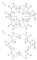
- FIGS. 9A-9D provide schematic views of another example of an alternate embodiment of the present invention.
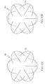
- FIGS. 10A-10D provide schematic views of another example of an alternate embodiment of the present invention.
- FIG. 1 shows a single multi-legged link 10 according to a preferred embodiment of the present invention.
- the link is preferably molded from a plastic material, which is preferably polypropylene.
- the link 10 includes a pair of linkage legs 12 , 14 angled with respect to each other at approximately a 60-degree angle and integrally coupled to a substantially curved base portion 16 at their origin ends.
- each linkage leg is about 85 mm in length.
- a third support leg 18 preferably, measuring about 90 mm in length, also extends from the curved base portion 16 midway between the two linkage legs 12 , 14 .
- Each of the linkage legs 12 , 14 include a plurality of cylindrical projections 20 extending from an upper surface thereof and spaced evenly therealong and a plurality of quadrilateral projections 22 extending from a lower surface thereof and arranged uniformly therealong.
- the support leg 18 also includes a plurality of cylindrical projections 24 extending from the upper and lower surfaces thereof and distributed uniformly therealong.
- the cylindrical projections 20 , 24 and the quadrilateral projections 22 have a height of about 2 mm.
- each of the linkage legs 12 , 14 also includes a plurality of transverse slots 26 cut into the upper surfaces thereof, extending diagonally towards the origin end from the outer side to the inner side of the linkage leg.
- the transverse slots 26 will be cut at an angle that is approximately 60 degrees from the support leg 18 (i.e., the centerline extending between each of the linkage legs).
- each slot 26 includes a number stamped therein that is visible by a user (see FIG. 7 B). This number indicates to the user the size of the platform that would be created if this slot were used for all the links engaging with one another to create the assembled platform.
- the outermost slot includes the number “12” (corresponding to a 12-inch diameter platform), the next innermost slot includes the number “10” (corresponding to a 10-inch diameter platform), the next innermost slot includes the number “8” (corresponding to an 8-inch diameter platform), and the innermost slot includes the number “6” (corresponding to a 6-inch diameter platform).
- Scribe lines 28 are etched or molded into the lateral side surfaces of each leg and are located approximately in the last third region of the legs. These scribe lines are designed to allow the user to break off these end portions of the legs at the scribe lines when the links are to be assembled to create platforms of the smaller diameters. This may be necessary in certain embodiments because, otherwise, the legs of all the assembled pieces will interfere with each other to prevent assembly in these minimum configurations.
- the curved base portion 16 also includes a plurality of projections 30 extending from its upper and lower surfaces.
- the projections 30 have a height of about 2 mm.
- a platform is assembled by arranging the links in an alternating upward facing and downward facing fashion so that the linkage legs 12 , 14 , form an outer enclosed loop.
- the slot 26 a in a linkage leg 12 a of an upward facing link 10 a will be engaged with a similarly numbered slot 26 b in an immediately adjacent linkage leg 12 b of an adjacent downwardly facing link 10 b .
- the next upwardly facing link 10 c will be coupled to the downwardly facing link 10 b by engaging the slot 26 c in linkage leg 14 c with the slot in linkage leg 14 b .
- the last downwardly facing link 10 d will be coupled between the two upwardly facing links 10 a and 10 c by engaging the slot 26 d in linkage leg 12 d with slot 26 c in linkage leg 12 c , and by engaging slot 26 d in linkage leg 14 d with slot 26 a in linkage leg 14 a.
- the links 10 a , 10 b , 10 c & 10 d hold together, one to the other, by a friction fit in the slots and also, to some degree, by tension created in the plastic components when the parts are joined together as a unit of four pieces.
- the individual link 10 is designed so that it is necessary to lightly squeeze the outer ends of the linkage legs 12 , 14 inward in order to be joined together in the four components. This creates a holding tension in the links due to the elasticity of the plastic.
- the projections 20 , 22 , 24 and 30 in combination with the spaces between the legs 12 , 14 & 18 , allow air and moisture to pass beneath or over the assembled platform when it is placed on supporting surface, such as a porch deck, and when a potted plant is placed on the upper surface of the assembled platform.
- FIG. 4 illustrates an assembled platform 32 a , where the links 10 a - 10 d have been assembled together at their maximum diameter.
- FIG. 5 illustrates an assembled platform 32 b , where the links 10 a - 10 d have been assembled together in their minimum diameter (note that the ends of the legs 12 , 14 & 18 have been removed at the scribe lines 28 to provide clearance for this assembly of the platform).
- FIG. 6 illustrates an assembled platform 32 c , where the links 10 a - 10 d have been assembled together in an oblong-type orientation. With this oblong arrangement, for example, the numbers “12”—“12” and “8”—“8” correspond to the engaging slot numbers of the coupled linkage legs used to create this configuration. It will be understood by those of ordinary skill in the art that many different symmetric and oblong configurations are achievable by using the preferred embodiment.
- FIGS. 8-10 provide some examples of such alternate embodiments that fall within the scope of the invention.
- FIG. 8A shows an overhead view of an adjustable platform 34 having four links 36 where each link includes two elongated 38 linkage legs connected at a right angle to the base portion 40 .
- FIG. 8B shows an overhead view of an adjustable platform 34 ′ having four links 36 ′, similar to those used in FIG. 8A with each link 36 ′ being modified by the addition of an elongated support leg 42 , the support leg being attached to the midpoint of base portion 40 ′.
- FIG. 8C depicts the same platform 34 shown in FIG. 8A, illustrating a potted plant 44 as it might rest on the platform 34 .
- FIG. 8D depicts the same platform 34 ′ shown in FIG. 8B, illustrating a potted plant 44 as it might rest on the platform 34 ′.
- FIG. 9A shows an overhead view of an adjustable platform 46 having two links 48 , each link having two elongated linkage legs 50 connected at a obtuse angle to the base portion 52 .
- FIG. 9B shows an overhead view of an adjustable platform 46 ′ having two links 48 ′, similar to those used in FIG. 9A with each link 48 ′ being modified by the addition of a pair of elongated support legs 54 , the support legs 54 extending between the linkage legs 50 ′, from the midpoint of base portion 52 ′.
- FIG. 9C depicts the same platform 46 shown in FIG. 9A, illustrating a potted plant 56 as it might rest on the platform 46 .
- FIG. 9D depicts the same platform 46 ′ shown in FIG. 9B, illustrating a number of different-sized potted plants 58 as they might rest on the platform 46 ′, thereby illustrating the versatility and adaptability of the adjustable platform of the present invention.
- FIG. 10A shows an overhead view of an adjustable platform 60 having six links 62 where each link includes two elongated linkage legs 64 connected to form an arc with the base portion 66 .
- FIG. 10B shows an overhead view of an adjustable platform 80 ′ having six links 62 ′, similar to those used in FIG. 10A with each link 62 ′ being modified by the addition of an elongated support leg 68 , the support leg 68 being attached to the midpoint of base portion 66 ′ and extending between the linkage legs 64 ′.
- FIG. 10C depicts the same platform 60 shown in FIG. 10A, illustrating a potted plant 70 as it might rest on the platform 60 .
- FIG. 10D depicts the same platform 60 ′ shown in FIG. 10B, illustrating a potted plant 70 as it might rest on the platform 60 ′.
Abstract
Description
Claims (19)
Priority Applications (4)
| Application Number | Priority Date | Filing Date | Title |
|---|---|---|---|
| US09/754,436 US6487815B2 (en) | 2000-05-01 | 2001-01-04 | Adjustable protective platform for supporting potted plants |
| TW090107225A TW561033B (en) | 2000-05-01 | 2001-03-27 | Adjustable protective platform for supporting and aerating potted plants, link of same and method of adjusting support area of same |
| CN01117172A CN1321845A (en) | 2000-05-01 | 2001-04-27 | Adjustable protective platform for supporting potted plant |
| HK02103619.3A HK1041916A1 (en) | 2000-05-01 | 2002-05-14 | Adjustable protective platform for supporting potted plants |
Applications Claiming Priority (2)
| Application Number | Priority Date | Filing Date | Title |
|---|---|---|---|
| US20103000P | 2000-05-01 | 2000-05-01 | |
| US09/754,436 US6487815B2 (en) | 2000-05-01 | 2001-01-04 | Adjustable protective platform for supporting potted plants |
Publications (2)
| Publication Number | Publication Date |
|---|---|
| US20010049904A1 US20010049904A1 (en) | 2001-12-13 |
| US6487815B2 true US6487815B2 (en) | 2002-12-03 |
Family
ID=26896317
Family Applications (1)
| Application Number | Title | Priority Date | Filing Date |
|---|---|---|---|
| US09/754,436 Expired - Fee Related US6487815B2 (en) | 2000-05-01 | 2001-01-04 | Adjustable protective platform for supporting potted plants |
Country Status (4)
| Country | Link |
|---|---|
| US (1) | US6487815B2 (en) |
| CN (1) | CN1321845A (en) |
| HK (1) | HK1041916A1 (en) |
| TW (1) | TW561033B (en) |
Cited By (1)
| Publication number | Priority date | Publication date | Assignee | Title |
|---|---|---|---|---|
| US20140165464A1 (en) * | 2012-04-02 | 2014-06-19 | Barry D. Setzer | Above-ground planting bed |
Families Citing this family (1)
| Publication number | Priority date | Publication date | Assignee | Title |
|---|---|---|---|---|
| CN104791343B (en) * | 2015-04-24 | 2017-02-01 | 吴中区光福明仕阁古典家具厂 | Pentagram-shaped connecting structure |
Citations (6)
| Publication number | Priority date | Publication date | Assignee | Title |
|---|---|---|---|---|
| US440141A (en) * | 1890-11-11 | Flower structure | ||
| US986395A (en) * | 1909-07-28 | 1911-03-07 | Gertrude M King | Plant and flower pot. |
| US5406745A (en) * | 1992-12-09 | 1995-04-18 | Lin; Chin T. | Honeycomb grassplanting unit |
| USD444113S1 (en) * | 2000-11-14 | 2001-06-26 | Leila R. Leary | Sun shield |
| USD445061S1 (en) * | 2000-05-01 | 2001-07-17 | Hanover Direct, Inc. | Potted plant platform link |
| USD445359S1 (en) * | 2000-05-01 | 2001-07-24 | Hanover Direct, Inc. | Potted plant platform |
-
2001
- 2001-01-04 US US09/754,436 patent/US6487815B2/en not_active Expired - Fee Related
- 2001-03-27 TW TW090107225A patent/TW561033B/en active
- 2001-04-27 CN CN01117172A patent/CN1321845A/en active Pending
-
2002
- 2002-05-14 HK HK02103619.3A patent/HK1041916A1/en unknown
Patent Citations (6)
| Publication number | Priority date | Publication date | Assignee | Title |
|---|---|---|---|---|
| US440141A (en) * | 1890-11-11 | Flower structure | ||
| US986395A (en) * | 1909-07-28 | 1911-03-07 | Gertrude M King | Plant and flower pot. |
| US5406745A (en) * | 1992-12-09 | 1995-04-18 | Lin; Chin T. | Honeycomb grassplanting unit |
| USD445061S1 (en) * | 2000-05-01 | 2001-07-17 | Hanover Direct, Inc. | Potted plant platform link |
| USD445359S1 (en) * | 2000-05-01 | 2001-07-24 | Hanover Direct, Inc. | Potted plant platform |
| USD444113S1 (en) * | 2000-11-14 | 2001-06-26 | Leila R. Leary | Sun shield |
Non-Patent Citations (1)
| Title |
|---|
| Photographs of "Sheer Garden Deck Protector". |
Cited By (2)
| Publication number | Priority date | Publication date | Assignee | Title |
|---|---|---|---|---|
| US20140165464A1 (en) * | 2012-04-02 | 2014-06-19 | Barry D. Setzer | Above-ground planting bed |
| US9155252B2 (en) * | 2012-04-02 | 2015-10-13 | Barry D. Setzer | Above-ground planting bed |
Also Published As
| Publication number | Publication date |
|---|---|
| HK1041916A1 (en) | 2002-07-26 |
| TW561033B (en) | 2003-11-11 |
| CN1321845A (en) | 2001-11-14 |
| US20010049904A1 (en) | 2001-12-13 |
Similar Documents
| Publication | Publication Date | Title |
|---|---|---|
| US7913452B1 (en) | Plant pot arrangement | |
| EP0811331A3 (en) | Molded surface fastener | |
| US4270748A (en) | Modularized slide | |
| US20100313472A1 (en) | Support for plants | |
| US6688239B1 (en) | Holiday tree display tables | |
| JPH0349242B2 (en) | ||
| EP1155642B1 (en) | Cot assembly | |
| US6672968B2 (en) | Modular skate park system | |
| US20210321752A1 (en) | Free-standing hammock stand | |
| EP1028618B1 (en) | Clip, as well as wire/clip assembly | |
| US6487815B2 (en) | Adjustable protective platform for supporting potted plants | |
| US20060117628A1 (en) | Locking plant tag | |
| US6029584A (en) | Furniture assembly | |
| US6454225B1 (en) | Stand for a potted plant | |
| WO2001003495A1 (en) | Tie | |
| USD450496S1 (en) | Table base | |
| US6564400B2 (en) | Continuous tube cot assembly | |
| US20020095862A1 (en) | Stackable landscape edging and methods of manufacturing and using same | |
| US6237881B1 (en) | Convertible table and flower pot holder | |
| US20060090675A1 (en) | Modular folding tables | |
| US5535847A (en) | Table top attachment for sawhorses | |
| GB2178931A (en) | Supports | |
| EP1067854B1 (en) | Torsion coil spring | |
| US4803805A (en) | Flower arranging device | |
| CA2238914C (en) | Plant pot with saucer |
Legal Events
| Date | Code | Title | Description |
|---|---|---|---|
| AS | Assignment |
Owner name: HANOVER DIRECT, INC., NEW JERSEY Free format text: ASSIGNMENT OF ASSIGNORS INTEREST;ASSIGNOR:RIMBACK, PETER D.;REEL/FRAME:011764/0919 Effective date: 20001219 |
|
| AS | Assignment |
Owner name: HSN IMPROVEMENTS, LLC, FLORIDA Free format text: ASSET PURCHASE AGREEMENT;ASSIGNOR:HANOVER BRANDS, INC.;REEL/FRAME:012119/0098 Effective date: 20010613 |
|
| AS | Assignment |
Owner name: HANOVER BRANDS, INC., NEW JERSEY Free format text: PARTIAL RELEASE OF SECURITY INTEREST;ASSIGNOR:CONGRESS FINANCIAL CORPORATION;REEL/FRAME:012302/0185 Effective date: 20010629 Owner name: HSN IMPROVEMENTS, LLC, FLORIDA Free format text: ASSIGNMENT OF ASSIGNORS INTEREST;ASSIGNOR:HANOVER DIRECT, INC.;REEL/FRAME:012303/0909 Effective date: 20010629 |
|
| AS | Assignment |
Owner name: HSN IMPROVEMENTS, LLC, FLORIDA Free format text: ASSET PURCHASE AGREEMENT;ASSIGNOR:HANOVER DIRECT, INC.;REEL/FRAME:014289/0504 Effective date: 20010613 |
|
| FEPP | Fee payment procedure |
Free format text: PAYOR NUMBER ASSIGNED (ORIGINAL EVENT CODE: ASPN); ENTITY STATUS OF PATENT OWNER: LARGE ENTITY |
|
| FPAY | Fee payment |
Year of fee payment: 4 |
|
| AS | Assignment |
Owner name: BANK OF AMERICA, N.A., AS COLLATERAL AGENT, TEXAS Free format text: SECURITY AGREEMENT;ASSIGNORS:CINMAR, L.P.;GARNET HILL, INC.;HSN IMPROVEMENTS, LLC;AND OTHERS;REEL/FRAME:021511/0679 Effective date: 20080820 Owner name: BANK OF AMERICA, N.A., AS COLLATERAL AGENT,TEXAS Free format text: SECURITY AGREEMENT;ASSIGNORS:CINMAR, L.P.;GARNET HILL, INC.;HSN IMPROVEMENTS, LLC;AND OTHERS;REEL/FRAME:021511/0679 Effective date: 20080820 |
|
| REMI | Maintenance fee reminder mailed | ||
| LAPS | Lapse for failure to pay maintenance fees | ||
| STCH | Information on status: patent discontinuation |
Free format text: PATENT EXPIRED DUE TO NONPAYMENT OF MAINTENANCE FEES UNDER 37 CFR 1.362 |
|
| FP | Lapsed due to failure to pay maintenance fee |
Effective date: 20101203 |
|
| AS | Assignment |
Owner name: HSN IMPROVEMENTS, LLC, FLORIDA Free format text: RELEASE BY SECURED PARTY;ASSIGNOR:BANK OF AMERICA, N.A.;REEL/FRAME:028135/0722 Effective date: 20120427 |