EP1154203A2 - Messeinrichtung für eine Flamme - Google Patents
Messeinrichtung für eine Flamme Download PDFInfo
- Publication number
- EP1154203A2 EP1154203A2 EP01107100A EP01107100A EP1154203A2 EP 1154203 A2 EP1154203 A2 EP 1154203A2 EP 01107100 A EP01107100 A EP 01107100A EP 01107100 A EP01107100 A EP 01107100A EP 1154203 A2 EP1154203 A2 EP 1154203A2
- Authority
- EP
- European Patent Office
- Prior art keywords
- flame
- voltage
- measuring device
- signal
- burner
- Prior art date
- Legal status (The legal status is an assumption and is not a legal conclusion. Google has not performed a legal analysis and makes no representation as to the accuracy of the status listed.)
- Granted
Links
- 230000003068 static effect Effects 0.000 claims abstract description 3
- 230000001960 triggered effect Effects 0.000 claims description 4
- 230000001419 dependent effect Effects 0.000 abstract description 3
- 239000000470 constituent Substances 0.000 abstract 5
- 238000005259 measurement Methods 0.000 abstract 1
- 230000001105 regulatory effect Effects 0.000 abstract 1
- 239000003990 capacitor Substances 0.000 description 3
- 230000001681 protective effect Effects 0.000 description 2
- 238000010276 construction Methods 0.000 description 1
- 238000010586 diagram Methods 0.000 description 1
- 238000011156 evaluation Methods 0.000 description 1
- 238000000034 method Methods 0.000 description 1
- 238000012544 monitoring process Methods 0.000 description 1
- 238000001208 nuclear magnetic resonance pulse sequence Methods 0.000 description 1
- 230000035945 sensitivity Effects 0.000 description 1
- 238000000926 separation method Methods 0.000 description 1
- 230000008054 signal transmission Effects 0.000 description 1
Images

Classifications
-
- F—MECHANICAL ENGINEERING; LIGHTING; HEATING; WEAPONS; BLASTING
- F23—COMBUSTION APPARATUS; COMBUSTION PROCESSES
- F23N—REGULATING OR CONTROLLING COMBUSTION
- F23N5/00—Systems for controlling combustion
- F23N5/02—Systems for controlling combustion using devices responsive to thermal changes or to thermal expansion of a medium
- F23N5/12—Systems for controlling combustion using devices responsive to thermal changes or to thermal expansion of a medium using ionisation-sensitive elements, i.e. flame rods
- F23N5/123—Systems for controlling combustion using devices responsive to thermal changes or to thermal expansion of a medium using ionisation-sensitive elements, i.e. flame rods using electronic means
Definitions
- the present invention relates to a measuring device for a flame according to claim 1.
- the invention also relates to a control device for a burner with the Measuring device for a flame according to claim 1.
- the present invention is based on the object of a measuring device for a flame to provide the type mentioned above, which is more accurate and improved Signal evaluation enabled.
- the essence of the invention is therefore that the alternating component influenced by the flame signal exceeds the first means can be separated from the DC voltage component and the separated AC component with the separated DC voltage component is comparable by a second means generate pulse width modulated signal.
- Fig. 1 shows schematically the principle of operation of the circuit according to the invention.
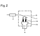
- the flame 14 shown in FIG. 2 with the ionization electrode 15 is represented by a diode 1a and a resistor 1b.
- An AC voltage of, for example, 230V is applied via L and N. If a flame is present, a larger current flows through the block capacitor 3 in the positive half-wave than in the negative half-wave due to the flame diode la. This forms a positive DC voltage U B at the block capacitor 3 between L and a resistor 2 attached for the purpose of protection against contact.
- a decoupling resistor 4 therefore flows a direct current from N to the block capacitor 3. The level of the direct current depends on U B and thus directly on the flame resistance 1b.
- the flame resistor 1b also influences the alternating current through the decoupling resistor 4, but to a different degree compared to the direct current.
- a direct current and an alternating current thus flow through the resistor 4 as described above.
- the resistor 4 is now followed by a high pass 5 and a low pass 6.
- the high-pass filter 5 filters out the alternating current and blocks the direct-current component.
- the low-pass filter filters out the DC component, which is dependent on the flame resistance 1b, and essentially blocks the AC current.
- the alternating current flowing from the high pass 5 is amplified in an amplifier 7 and a reference voltage U Ref is added.
- the direct current flowing out of the high pass 6 is amplified with possibly small alternating current components and a reference voltage U Ref is added.
- the retriggerable monoflop 11 thus forms a "missing pulse detector" which is the dynamic on - / off signal converted into a static on / off signal.
- Both signals, the PWM signal and the flame signal can now be processed separately are or can be linked by an OR gate 12.
- the pulse duty factor of which is a measure for the flame resistance is 1b. If there is no flame, the output of the OR gate is permanent at 1.
- the PWM signal can be via an optocoupler, not shown be transferred to a protective separation between the network side and the To reach the protective extra-low voltage side.
- Figure 2 shows the actual structure of the diode shown in Figure 1 as an equivalent circuit 1 1a and the resistor 1b, as is also known for example from DE 196 32 983 A1.
- a flame 14 can be generated by a burner 13.
- Ionization electrode 15 which detects the ionization current. This depends on Flame resistance and thus the electrode temperature.
- the electrode temperature in turn depends on the lambda value and thus the excess air of the one to be burned Mix off.
- the ratio of air to gas can be set using the lambda value become.
- the lambda value between 1.15 and 1.3 is chosen to be a to achieve super-stoichiometric ratio of air to gas
Landscapes
- Engineering & Computer Science (AREA)
- Chemical & Material Sciences (AREA)
- Combustion & Propulsion (AREA)
- Mechanical Engineering (AREA)
- General Engineering & Computer Science (AREA)
- Other Investigation Or Analysis Of Materials By Electrical Means (AREA)
- Control Of Combustion (AREA)
- Fire-Detection Mechanisms (AREA)
- Investigating, Analyzing Materials By Fluorescence Or Luminescence (AREA)
Abstract
Description
Weitere Vorteile sind der in einem weiten Bereich einstellbare Signalhub, die grosse Empfindlichkeit und der grosse Signal-Störabstand ob die Flamme Ein oder Aus ist sowie dass das analoge Signal sehr genau und reproduzierbar ist.
So ist die Signalübertragung über einen Optokoppler möglich, wobei beide Informationen, Flamme Ein und Aus und PWM-Signal über nur einen Optokoppler übertragen werden können. Durch den Einbau von Berührschutz-Widerständen kann die Ionisationselektrode berührsicher ausgestaltet werden.
- Fig. 1
- Blockschaltbild des erfindungsgemässen Aufbaus;
- Fig. 2
- tatsächlicher Aufbau der in Figur 1 als Ersatzschaltung 1 dargestellten Flamme mit Ionisationselektrode.
Der Gleichspannungsanteil U= wird in einem Komparator 10 mit der Referenzspannung URef verglichen. Ist eine Flamme vorhanden, ist der Gleichspannungsanteil grösser als die Referenzspannung (U= > URef) und der Komparatorausgang des Komparators 10 schaltet auf 0. Ist keine Flamme vorhanden, so ist der Gleichspannungsanteil ungefähr gleich der Referenzspannung (U= ≈ URef). Wegen dem Gleichspannungsanteil überlagerten, geringen Wechselspannungsanteil, den der Tiefpass 6 nicht ausfiltert, unterschreitet der Gleichspannungsanteil kurzzeitig die Referenzspannung und am Komparatorausgang des Komparators 10 erscheinen Impulse. Diese Impulse werden auf ein nachtriggerbares Monoflop 11 gegeben. Das Monoflop wird so getriggert, dass die aus dem Komparator 10 ausgegebene Impulsfolge schneller kommt als die Impulsdauer des Monoflops ist. Dadurch erscheint wenn keine Flamme vorhanden ist am Ausgang des Monoflops konstant eine 1. Ist eine Flamme vorhanden, so wird das Monoflop nicht getriggert und am Ausgang erscheint permanent eine 0. Das nachtriggerbare Monoflop 11 bildet somit einen "missing pulse detector" welches das dynamische Ein-/Aus-Signal in ein statisches Ein-/Aus-Signal umwandelt.
Claims (10)
- Messeinrichtung für eine Flamme, insbesondere zur Verwendung in einer Regeleinrichtung für einen Brenner (13), mit einer im Flammenbereich (14) des Brenners angeordneten Ionisationselektrode (15), auf die eine Wechselspannung aufgeschaltet ist, wodurch sich in Abhängigkeit vom Ionisationsstrom ein Gleichspannungsanteil überlagert,
dadurch gekennzeichnet, dass der vom Flammenwiderstand beeinflusste Wechselspannungsanteil über erste Mittel (5, 6) vom Gleichspannungsanteil trennbar ist und die getrennte Wechselspannung mit dem abgetrennten Gleichspannungsanteil über zweite Mittel (9, 10) vergleichbar ist um ein pulsweitenmoduliertes Signal zu erzeugen. - Messeinrichtung nach Anspruch 1,
dadurch gekennzeichnet, dass die Wechselspannung und der Gleichspannungsanteil mittels eines Hochpasses (5) und eines Tiefpasses (6) voneinander trennbar sind. - Messeinrichtung nach Anspruch 1 oder 2,
dadurch gekennzeichnet, dass die Wechselspannung und der Gleichspannungsanteil mittels eines Komparators (9) vergleichbar ist. - Messeinrichtung nach einem der Ansprüche 1, 2 oder 3,
dadurch gekennzeichnet, dass der Gleichspannungsanteil mittels eines Komparators (10) mit einer Referenzspannung (URef) vergleichbar ist um als Flammensignal verwendet zu werden. - Messeinrichtung nach Anspruch 4,
dadurch gekennzeichnet, dass das Flammensignal an ein getriggertes Monoflop (11) gelegt ist um ein statisches Ein-/Aus-Signal zu bilden. - Messeinrichtung nach einem der vorherigen Ansprüche,
dadurch gekennzeichnet, dass das über ein Monoflop (11) getriggerte Flammensignal mit dem pulsweitenmoduliertes Signal in einem Oder-Glied (12) verknüpft ist. - Messeinrichtung nach Anspruch 6,
dadurch gekennzeichnet, dass das aus dem Oder-Glied (12) ausgegebene Signal über einen Optokoppler übertragbar ist. - Messeinrichtung nach einem der vorherigen Ansprüche,
dadurch gekennzeichnet, dass in Serie zur Ionisationselektrode (15) mindestens ein Widerstand (2) als Berührschutz gelegt ist. - Regeleinrichtung für einen Brenner (13) mit der Messeinrichtung nach einem der Ansprüche 1 bis 8.
- Verwendung der Messeinrichtung nach einem der Ansprüche 1 - 8 in einem Feuerungsautomaten.
Applications Claiming Priority (2)
| Application Number | Priority Date | Filing Date | Title |
|---|---|---|---|
| DE10023273A DE10023273A1 (de) | 2000-05-12 | 2000-05-12 | Messeinrichtung für eine Flamme |
| DE10023273 | 2000-05-12 |
Publications (4)
| Publication Number | Publication Date |
|---|---|
| EP1154203A2 true EP1154203A2 (de) | 2001-11-14 |
| EP1154203A3 EP1154203A3 (de) | 2003-05-14 |
| EP1154203B1 EP1154203B1 (de) | 2006-08-23 |
| EP1154203B2 EP1154203B2 (de) | 2015-07-15 |
Family
ID=7641776
Family Applications (1)
| Application Number | Title | Priority Date | Filing Date |
|---|---|---|---|
| EP01107100.8A Expired - Lifetime EP1154203B2 (de) | 2000-05-12 | 2001-03-22 | Messeinrichtung für eine Flamme |
Country Status (6)
| Country | Link |
|---|---|
| US (1) | US6676404B2 (de) |
| EP (1) | EP1154203B2 (de) |
| JP (1) | JP4965028B2 (de) |
| KR (1) | KR100778145B1 (de) |
| AT (1) | ATE337525T1 (de) |
| DE (2) | DE10023273A1 (de) |
Cited By (4)
| Publication number | Priority date | Publication date | Assignee | Title |
|---|---|---|---|---|
| WO2010094673A1 (en) | 2009-02-20 | 2010-08-26 | Bekaert Combust. Technol. B.V. | Premix gas burner with improved flame monitoring and control |
| WO2012076600A1 (en) | 2010-12-09 | 2012-06-14 | Bekaert Combustion Technology B.V. | Burner with locally fixed burner deck |
| EP2865946A1 (de) * | 2013-10-23 | 2015-04-29 | Robert Bosch Gmbh | Vorrichtung zum Ermitteln eines Ionisationsstroms einer Flamme |
| WO2017080820A1 (de) * | 2015-11-11 | 2017-05-18 | Viessmann Werke Gmbh & Co. Kg | Verfahren und vorrichtung zur flammensignalerfassung |
Families Citing this family (36)
| Publication number | Priority date | Publication date | Assignee | Title |
|---|---|---|---|---|
| EP1702179B1 (de) * | 2003-12-11 | 2014-11-12 | ABB Inc. | Signalverarbeitung zum besseren unterscheiden von flammenscannern |
| US7492269B2 (en) * | 2005-02-24 | 2009-02-17 | Alstom Technology Ltd | Self diagonostic flame ignitor |
| US7764182B2 (en) * | 2005-05-12 | 2010-07-27 | Honeywell International Inc. | Flame sensing system |
| US8085521B2 (en) * | 2007-07-03 | 2011-12-27 | Honeywell International Inc. | Flame rod drive signal generator and system |
| US8310801B2 (en) * | 2005-05-12 | 2012-11-13 | Honeywell International, Inc. | Flame sensing voltage dependent on application |
| US8300381B2 (en) * | 2007-07-03 | 2012-10-30 | Honeywell International Inc. | Low cost high speed spark voltage and flame drive signal generator |
| US7768410B2 (en) * | 2005-05-12 | 2010-08-03 | Honeywell International Inc. | Leakage detection and compensation system |
| US8066508B2 (en) | 2005-05-12 | 2011-11-29 | Honeywell International Inc. | Adaptive spark ignition and flame sensing signal generation system |
| DE102005024763B3 (de) * | 2005-05-31 | 2006-06-08 | Stiebel Eltron Gmbh & Co. Kg | Heizgerät und Verfahren zum Steuern eines Heizgerätes |
| US8875557B2 (en) | 2006-02-15 | 2014-11-04 | Honeywell International Inc. | Circuit diagnostics from flame sensing AC component |
| RU2440536C2 (ru) * | 2006-05-11 | 2012-01-20 | Сит Ла Пречиса С.П.А. | Устройство для измерения интенсивности пламени |
| WO2007132484A1 (en) * | 2006-05-11 | 2007-11-22 | Sit La Precisa S.P.A. | A device for measuring flame intensity |
| WO2009110015A1 (en) * | 2008-03-07 | 2009-09-11 | Bertelli & Partners S.R.L. | Improved method and device to detect the flame in a burner operating on a solid, liquid or gaseous combustible |
| EP2154430B1 (de) | 2008-08-15 | 2015-09-30 | Siemens Aktiengesellschaft | Regeleinrichtung für einen Gasbrenner, sowie Verwendung einer solchen Regeleinrichtung |
| US9366433B2 (en) * | 2010-09-16 | 2016-06-14 | Emerson Electric Co. | Control for monitoring flame integrity in a heating appliance |
| US20150219333A1 (en) * | 2012-08-27 | 2015-08-06 | Clearsign Combustion Corporation | Electrodynamic combustion system with variable gain electrodes |
| US10208954B2 (en) | 2013-01-11 | 2019-02-19 | Ademco Inc. | Method and system for controlling an ignition sequence for an intermittent flame-powered pilot combustion system |
| US9494320B2 (en) | 2013-01-11 | 2016-11-15 | Honeywell International Inc. | Method and system for starting an intermittent flame-powered pilot combustion system |
| US9696034B2 (en) * | 2013-03-04 | 2017-07-04 | Clearsign Combustion Corporation | Combustion system including one or more flame anchoring electrodes and related methods |
| US9739479B2 (en) | 2013-03-28 | 2017-08-22 | Clearsign Combustion Corporation | Battery-powered high-voltage converter circuit with electrical isolation and mechanism for charging the battery |
| US10042375B2 (en) | 2014-09-30 | 2018-08-07 | Honeywell International Inc. | Universal opto-coupled voltage system |
| US10288286B2 (en) | 2014-09-30 | 2019-05-14 | Honeywell International Inc. | Modular flame amplifier system with remote sensing |
| US10678204B2 (en) | 2014-09-30 | 2020-06-09 | Honeywell International Inc. | Universal analog cell for connecting the inputs and outputs of devices |
| US10402358B2 (en) | 2014-09-30 | 2019-09-03 | Honeywell International Inc. | Module auto addressing in platform bus |
| EP3045816B1 (de) | 2015-01-19 | 2018-12-12 | Siemens Aktiengesellschaft | Einrichtung zur regelung einer brenneranlage |
| ES2902010T3 (es) | 2017-03-27 | 2022-03-24 | Siemens Ag | Detección de un bloqueo |
| KR102422728B1 (ko) * | 2017-12-21 | 2022-07-19 | 지오다노 컨트롤즈 에스.피.에이. | 가스 버너의 화염을 검출하고 제어하는 장치 및 방법 |
| US10473329B2 (en) | 2017-12-22 | 2019-11-12 | Honeywell International Inc. | Flame sense circuit with variable bias |
| US11236930B2 (en) | 2018-05-01 | 2022-02-01 | Ademco Inc. | Method and system for controlling an intermittent pilot water heater system |
| US10935237B2 (en) | 2018-12-28 | 2021-03-02 | Honeywell International Inc. | Leakage detection in a flame sense circuit |
| US11280811B2 (en) | 2019-06-17 | 2022-03-22 | Advanced Energy Industries, Inc. | High side current monitor |
| US11656000B2 (en) | 2019-08-14 | 2023-05-23 | Ademco Inc. | Burner control system |
| US11739982B2 (en) | 2019-08-14 | 2023-08-29 | Ademco Inc. | Control system for an intermittent pilot water heater |
| US12523690B2 (en) | 2021-03-17 | 2026-01-13 | Advanced Energy Industries, Inc. | Capacitance sensing systems and methods |
| US12038464B2 (en) | 2021-03-17 | 2024-07-16 | Advanced Energy Industries, Inc. | Capacitance sensing systems and methods |
| US12650451B2 (en) | 2023-04-24 | 2026-06-09 | Advanced Energy Industries, Inc. | Shielding for capacitance sensing |
Citations (1)
| Publication number | Priority date | Publication date | Assignee | Title |
|---|---|---|---|---|
| DE19632983A1 (de) | 1996-08-16 | 1998-02-19 | Stiebel Eltron Gmbh & Co Kg | Regeleinrichtung für einen Gasbrenner |
Family Cites Families (15)
| Publication number | Priority date | Publication date | Assignee | Title |
|---|---|---|---|---|
| GB1277402A (en) * | 1968-08-27 | 1972-06-14 | United Gas Industries Ltd | Flame detection system |
| GB1258327A (de) * | 1969-05-09 | 1971-12-30 | ||
| US3726630A (en) * | 1970-07-15 | 1973-04-10 | Liberty Combustion Corp | Flame ignition |
| JPS51140684A (en) * | 1975-05-28 | 1976-12-03 | Sony Corp | Flame detection apparatus |
| NL8401173A (nl) * | 1984-04-12 | 1985-11-01 | Philips Nv | Vlambeveiligingsschakeling. |
| US4871307A (en) * | 1988-11-02 | 1989-10-03 | Harris George W | Flame ignition and monitoring system and method |
| ATE107809T1 (de) * | 1990-04-30 | 1994-07-15 | Fraunhofer Ges Forschung | Verfahren und vorrichtung zur reduzierung des einschaltstromstosses beim betreiben einer induktivitätsbehafteten last. |
| DE4122636C2 (de) * | 1991-07-09 | 1999-08-12 | Bosch Gmbh Robert | Vorrichtung und Verfahren zum Überwachen einer Flamme |
| US5472337A (en) * | 1994-09-12 | 1995-12-05 | Guerra; Romeo E. | Method and apparatus to detect a flame |
| DE4433425C2 (de) * | 1994-09-20 | 1998-04-30 | Stiebel Eltron Gmbh & Co Kg | Regeleinrichtung zum Einstellen eines Gas-Verbrennungsluft-Gemisches bei einem Gasbrenner |
| DE19631821C2 (de) * | 1996-08-07 | 1999-08-12 | Stiebel Eltron Gmbh & Co Kg | Verfahren und Einrichtung zur Sicherheits-Flammenüberwachung bei einem Gasbrenner |
| EP0908679A1 (de) * | 1997-10-10 | 1999-04-14 | Electrowatt Technology Innovation AG | Flammenüberwachungsschaltung |
| US6084518A (en) * | 1999-06-21 | 2000-07-04 | Johnson Controls Technology Company | Balanced charge flame characterization system and method |
| DE10025769A1 (de) * | 2000-05-12 | 2001-11-15 | Siemens Building Tech Ag | Regeleinrichtung für einen Brenner |
| US6356199B1 (en) * | 2000-10-31 | 2002-03-12 | Abb Inc. | Diagnostic ionic flame monitor |
-
2000
- 2000-05-12 DE DE10023273A patent/DE10023273A1/de not_active Withdrawn
-
2001
- 2001-03-22 EP EP01107100.8A patent/EP1154203B2/de not_active Expired - Lifetime
- 2001-03-22 AT AT01107100T patent/ATE337525T1/de not_active IP Right Cessation
- 2001-03-22 DE DE50110780T patent/DE50110780D1/de not_active Expired - Lifetime
- 2001-04-27 JP JP2001130555A patent/JP4965028B2/ja not_active Expired - Lifetime
- 2001-05-01 US US09/846,700 patent/US6676404B2/en not_active Expired - Lifetime
- 2001-05-11 KR KR1020010025778A patent/KR100778145B1/ko not_active Expired - Lifetime
Patent Citations (1)
| Publication number | Priority date | Publication date | Assignee | Title |
|---|---|---|---|---|
| DE19632983A1 (de) | 1996-08-16 | 1998-02-19 | Stiebel Eltron Gmbh & Co Kg | Regeleinrichtung für einen Gasbrenner |
Cited By (5)
| Publication number | Priority date | Publication date | Assignee | Title |
|---|---|---|---|---|
| WO2010094673A1 (en) | 2009-02-20 | 2010-08-26 | Bekaert Combust. Technol. B.V. | Premix gas burner with improved flame monitoring and control |
| WO2012076600A1 (en) | 2010-12-09 | 2012-06-14 | Bekaert Combustion Technology B.V. | Burner with locally fixed burner deck |
| EP2865946A1 (de) * | 2013-10-23 | 2015-04-29 | Robert Bosch Gmbh | Vorrichtung zum Ermitteln eines Ionisationsstroms einer Flamme |
| WO2017080820A1 (de) * | 2015-11-11 | 2017-05-18 | Viessmann Werke Gmbh & Co. Kg | Verfahren und vorrichtung zur flammensignalerfassung |
| US10704785B2 (en) | 2015-11-11 | 2020-07-07 | Viessmann Werke Gmbh & Co. Kg | Method and device for flame signal detection |
Also Published As
| Publication number | Publication date |
|---|---|
| ATE337525T1 (de) | 2006-09-15 |
| DE50110780D1 (de) | 2006-10-05 |
| US20020004186A1 (en) | 2002-01-10 |
| DE10023273A1 (de) | 2001-11-15 |
| KR20010104274A (ko) | 2001-11-24 |
| KR100778145B1 (ko) | 2007-11-21 |
| EP1154203A3 (de) | 2003-05-14 |
| EP1154203B1 (de) | 2006-08-23 |
| US6676404B2 (en) | 2004-01-13 |
| JP4965028B2 (ja) | 2012-07-04 |
| EP1154203B2 (de) | 2015-07-15 |
| JP2001355840A (ja) | 2001-12-26 |
Similar Documents
| Publication | Publication Date | Title |
|---|---|---|
| EP1154203B2 (de) | Messeinrichtung für eine Flamme | |
| DE69023205T2 (de) | Schaltanordnung. | |
| DE69226277T2 (de) | Fail-safe fuehlerschaltung | |
| EP1719947B1 (de) | Verfahren und Vorrichtung zur Flammenüberwachung | |
| EP1293727B1 (de) | Regeleinrichtung für einen Brenner und Einstellverfahren | |
| DE19502901C1 (de) | Regeleinrichtung für einen Gasbrenner | |
| EP1983264B1 (de) | Flammenüberwachungsvorrichtung mit einer Spannungserzeugungs- und Messanordnung; Betriebsverfahren zur Vorrichtung | |
| DE69221737T2 (de) | Nachweis von teilchen in einer gasströmung | |
| EP0401225B1 (de) | Schaltgeregelte strömungssonde | |
| DE4410735B4 (de) | Einrichtung mit einem Feuerungsautomaten | |
| DE102019119206A1 (de) | Verfahren und Vorrichtung zur Anpassung der Empfindlichkeit eines Detektors zur Überwachung einer Flamme in einem Heizgerät | |
| EP0525345B2 (de) | Vorrichtung und Verfahren zum Überwachen einer Flamme | |
| EP0227908A1 (de) | Vorrichtung zur Spannungsmessung durch Abtastung | |
| DE19839160A1 (de) | Verfahren und Schaltung zur Regelung eines Gasbrenners | |
| EP1543319B1 (de) | Schaltungsanordnung zum betreiben einer linearen abgassonde | |
| DE19632983C2 (de) | Regeleinrichtung für einen Gasbrenner | |
| EP3374696B1 (de) | Verfahren und vorrichtung zur flammensignalerfassung | |
| DE19726169C2 (de) | Regeleinrichtung für einen Gasbrenner | |
| DE19844726A1 (de) | Stromsensor nach dem Kompensationsprinzip | |
| DE19947181B4 (de) | Verfahren zur Bestimmung eines für die aktuelle Luftzahl repräsentativen Signals | |
| EP2154430A1 (de) | Regeleinrichtung für einen Gasbrenner | |
| DE102020108006A1 (de) | Schaltungsvorrichtung und Verfahren zum Überwachen einer Brennerflamme | |
| DE102005024763B3 (de) | Heizgerät und Verfahren zum Steuern eines Heizgerätes | |
| DE19739317A1 (de) | Elektrische Schaltung für einen elektrochemischen Sensor | |
| DE19749891B4 (de) | Verfahren zur Messung der Konzentration eines Gases in einem Gasgemisch, insbesondere in Luft, und Vorrichtung zur Durchführung des Verfahrens |
Legal Events
| Date | Code | Title | Description |
|---|---|---|---|
| PUAI | Public reference made under article 153(3) epc to a published international application that has entered the european phase |
Free format text: ORIGINAL CODE: 0009012 |
|
| AK | Designated contracting states |
Kind code of ref document: A2 Designated state(s): AT BE CH CY DE DK ES FI FR GB GR IE IT LI LU MC NL PT SE TR |
|
| AX | Request for extension of the european patent |
Free format text: AL;LT;LV;MK;RO;SI |
|
| PUAL | Search report despatched |
Free format text: ORIGINAL CODE: 0009013 |
|
| AK | Designated contracting states |
Designated state(s): AT BE CH CY DE DK ES FI FR GB GR IE IT LI LU MC NL PT SE TR |
|
| AX | Request for extension of the european patent |
Extension state: AL LT LV MK RO SI |
|
| 17P | Request for examination filed |
Effective date: 20031103 |
|
| AKX | Designation fees paid |
Designated state(s): AT BE CH CY DE DK ES FI FR GB GR IE IT LI LU MC NL PT SE TR |
|
| RAP1 | Party data changed (applicant data changed or rights of an application transferred) |
Owner name: SIEMENS SCHWEIZ AG |
|
| GRAP | Despatch of communication of intention to grant a patent |
Free format text: ORIGINAL CODE: EPIDOSNIGR1 |
|
| GRAS | Grant fee paid |
Free format text: ORIGINAL CODE: EPIDOSNIGR3 |
|
| GRAA | (expected) grant |
Free format text: ORIGINAL CODE: 0009210 |
|
| AK | Designated contracting states |
Kind code of ref document: B1 Designated state(s): AT BE CH CY DE DK ES FI FR GB GR IE IT LI LU MC NL PT SE TR |
|
| PG25 | Lapsed in a contracting state [announced via postgrant information from national office to epo] |
Ref country code: FI Free format text: LAPSE BECAUSE OF FAILURE TO SUBMIT A TRANSLATION OF THE DESCRIPTION OR TO PAY THE FEE WITHIN THE PRESCRIBED TIME-LIMIT Effective date: 20060823 Ref country code: IE Free format text: LAPSE BECAUSE OF FAILURE TO SUBMIT A TRANSLATION OF THE DESCRIPTION OR TO PAY THE FEE WITHIN THE PRESCRIBED TIME-LIMIT Effective date: 20060823 Ref country code: IT Free format text: LAPSE BECAUSE OF FAILURE TO SUBMIT A TRANSLATION OF THE DESCRIPTION OR TO PAY THE FEE WITHIN THE PRESCRIBED TIME-LIMIT;WARNING: LAPSES OF ITALIAN PATENTS WITH EFFECTIVE DATE BEFORE 2007 MAY HAVE OCCURRED AT ANY TIME BEFORE 2007. THE CORRECT EFFECTIVE DATE MAY BE DIFFERENT FROM THE ONE RECORDED. Effective date: 20060823 |
|
| REG | Reference to a national code |
Ref country code: GB Ref legal event code: FG4D Free format text: NOT ENGLISH |
|
| REG | Reference to a national code |
Ref country code: CH Ref legal event code: EP |
|
| REG | Reference to a national code |
Ref country code: IE Ref legal event code: FG4D Free format text: LANGUAGE OF EP DOCUMENT: GERMAN |
|
| REF | Corresponds to: |
Ref document number: 50110780 Country of ref document: DE Date of ref document: 20061005 Kind code of ref document: P |
|
| PG25 | Lapsed in a contracting state [announced via postgrant information from national office to epo] |
Ref country code: SE Free format text: LAPSE BECAUSE OF FAILURE TO SUBMIT A TRANSLATION OF THE DESCRIPTION OR TO PAY THE FEE WITHIN THE PRESCRIBED TIME-LIMIT Effective date: 20061123 Ref country code: DK Free format text: LAPSE BECAUSE OF FAILURE TO SUBMIT A TRANSLATION OF THE DESCRIPTION OR TO PAY THE FEE WITHIN THE PRESCRIBED TIME-LIMIT Effective date: 20061123 |
|
| PG25 | Lapsed in a contracting state [announced via postgrant information from national office to epo] |
Ref country code: ES Free format text: LAPSE BECAUSE OF FAILURE TO SUBMIT A TRANSLATION OF THE DESCRIPTION OR TO PAY THE FEE WITHIN THE PRESCRIBED TIME-LIMIT Effective date: 20061204 |
|
| GBT | Gb: translation of ep patent filed (gb section 77(6)(a)/1977) |
Effective date: 20061129 |
|
| PG25 | Lapsed in a contracting state [announced via postgrant information from national office to epo] |
Ref country code: PT Free format text: LAPSE BECAUSE OF FAILURE TO SUBMIT A TRANSLATION OF THE DESCRIPTION OR TO PAY THE FEE WITHIN THE PRESCRIBED TIME-LIMIT Effective date: 20070124 |
|
| REG | Reference to a national code |
Ref country code: IE Ref legal event code: FD4D |
|
| ET | Fr: translation filed | ||
| PLBI | Opposition filed |
Free format text: ORIGINAL CODE: 0009260 |
|
| PLAX | Notice of opposition and request to file observation + time limit sent |
Free format text: ORIGINAL CODE: EPIDOSNOBS2 |
|
| 26 | Opposition filed |
Opponent name: STIEBEL ELTRON GMBH & CO.KG Effective date: 20070523 |
|
| NLR1 | Nl: opposition has been filed with the epo |
Opponent name: STIEBEL ELTRON GMBH & CO.KG |
|
| PLBB | Reply of patent proprietor to notice(s) of opposition received |
Free format text: ORIGINAL CODE: EPIDOSNOBS3 |
|
| REG | Reference to a national code |
Ref country code: CH Ref legal event code: PL |
|
| BERE | Be: lapsed |
Owner name: SIEMENS SCHWEIZ A.G. Effective date: 20070331 |
|
| PG25 | Lapsed in a contracting state [announced via postgrant information from national office to epo] |
Ref country code: BE Free format text: LAPSE BECAUSE OF NON-PAYMENT OF DUE FEES Effective date: 20070331 |
|
| PG25 | Lapsed in a contracting state [announced via postgrant information from national office to epo] |
Ref country code: MC Free format text: LAPSE BECAUSE OF NON-PAYMENT OF DUE FEES Effective date: 20070331 |
|
| PG25 | Lapsed in a contracting state [announced via postgrant information from national office to epo] |
Ref country code: CH Free format text: LAPSE BECAUSE OF NON-PAYMENT OF DUE FEES Effective date: 20070331 Ref country code: LI Free format text: LAPSE BECAUSE OF NON-PAYMENT OF DUE FEES Effective date: 20070331 |
|
| PG25 | Lapsed in a contracting state [announced via postgrant information from national office to epo] |
Ref country code: GR Free format text: LAPSE BECAUSE OF FAILURE TO SUBMIT A TRANSLATION OF THE DESCRIPTION OR TO PAY THE FEE WITHIN THE PRESCRIBED TIME-LIMIT Effective date: 20061124 |
|
| PG25 | Lapsed in a contracting state [announced via postgrant information from national office to epo] |
Ref country code: AT Free format text: LAPSE BECAUSE OF NON-PAYMENT OF DUE FEES Effective date: 20070322 |
|
| PG25 | Lapsed in a contracting state [announced via postgrant information from national office to epo] |
Ref country code: CY Free format text: LAPSE BECAUSE OF FAILURE TO SUBMIT A TRANSLATION OF THE DESCRIPTION OR TO PAY THE FEE WITHIN THE PRESCRIBED TIME-LIMIT Effective date: 20060823 Ref country code: LU Free format text: LAPSE BECAUSE OF NON-PAYMENT OF DUE FEES Effective date: 20070322 |
|
| PG25 | Lapsed in a contracting state [announced via postgrant information from national office to epo] |
Ref country code: TR Free format text: LAPSE BECAUSE OF FAILURE TO SUBMIT A TRANSLATION OF THE DESCRIPTION OR TO PAY THE FEE WITHIN THE PRESCRIBED TIME-LIMIT Effective date: 20060823 |
|
| PLCK | Communication despatched that opposition was rejected |
Free format text: ORIGINAL CODE: EPIDOSNREJ1 |
|
| APBM | Appeal reference recorded |
Free format text: ORIGINAL CODE: EPIDOSNREFNO |
|
| APBP | Date of receipt of notice of appeal recorded |
Free format text: ORIGINAL CODE: EPIDOSNNOA2O |
|
| APAH | Appeal reference modified |
Free format text: ORIGINAL CODE: EPIDOSCREFNO |
|
| APBQ | Date of receipt of statement of grounds of appeal recorded |
Free format text: ORIGINAL CODE: EPIDOSNNOA3O |
|
| PG25 | Lapsed in a contracting state [announced via postgrant information from national office to epo] |
Ref country code: DE Free format text: LAPSE BECAUSE OF NON-PAYMENT OF DUE FEES Effective date: 20111001 |
|
| APBU | Appeal procedure closed |
Free format text: ORIGINAL CODE: EPIDOSNNOA9O |
|
| REG | Reference to a national code |
Ref country code: FR Ref legal event code: PLFP Year of fee payment: 15 |
|
| PUAH | Patent maintained in amended form |
Free format text: ORIGINAL CODE: 0009272 |
|
| STAA | Information on the status of an ep patent application or granted ep patent |
Free format text: STATUS: PATENT MAINTAINED AS AMENDED |
|
| 27A | Patent maintained in amended form |
Effective date: 20150715 |
|
| AK | Designated contracting states |
Kind code of ref document: B2 Designated state(s): AT BE CH CY DE DK ES FI FR GB GR IE IT LI LU MC NL PT SE TR |
|
| REG | Reference to a national code |
Ref country code: DE Ref legal event code: R102 Ref document number: 50110780 Country of ref document: DE |
|
| REG | Reference to a national code |
Ref country code: FR Ref legal event code: CA Effective date: 20151007 |
|
| REG | Reference to a national code |
Ref country code: NL Ref legal event code: FP |
|
| REG | Reference to a national code |
Ref country code: FR Ref legal event code: PLFP Year of fee payment: 16 |
|
| REG | Reference to a national code |
Ref country code: FR Ref legal event code: PLFP Year of fee payment: 17 |
|
| REG | Reference to a national code |
Ref country code: FR Ref legal event code: PLFP Year of fee payment: 18 |
|
| PGFP | Annual fee paid to national office [announced via postgrant information from national office to epo] |
Ref country code: IT Payment date: 20200326 Year of fee payment: 20 Ref country code: NL Payment date: 20200311 Year of fee payment: 20 Ref country code: GB Payment date: 20200311 Year of fee payment: 20 |
|
| PGFP | Annual fee paid to national office [announced via postgrant information from national office to epo] |
Ref country code: FR Payment date: 20200316 Year of fee payment: 20 |
|
| PGFP | Annual fee paid to national office [announced via postgrant information from national office to epo] |
Ref country code: DE Payment date: 20200519 Year of fee payment: 20 |
|
| REG | Reference to a national code |
Ref country code: DE Ref legal event code: R071 Ref document number: 50110780 Country of ref document: DE |
|
| REG | Reference to a national code |
Ref country code: NL Ref legal event code: MK Effective date: 20210321 |
|
| REG | Reference to a national code |
Ref country code: GB Ref legal event code: PE20 Expiry date: 20210321 |
|
| PG25 | Lapsed in a contracting state [announced via postgrant information from national office to epo] |
Ref country code: GB Free format text: LAPSE BECAUSE OF EXPIRATION OF PROTECTION Effective date: 20210321 |