EP1153805A2 - Safety device for bearing of pedals - Google Patents
Safety device for bearing of pedals Download PDFInfo
- Publication number
- EP1153805A2 EP1153805A2 EP01109739A EP01109739A EP1153805A2 EP 1153805 A2 EP1153805 A2 EP 1153805A2 EP 01109739 A EP01109739 A EP 01109739A EP 01109739 A EP01109739 A EP 01109739A EP 1153805 A2 EP1153805 A2 EP 1153805A2
- Authority
- EP
- European Patent Office
- Prior art keywords
- pedal
- safety device
- collision
- bearing block
- guide
- Prior art date
- Legal status (The legal status is an assumption and is not a legal conclusion. Google has not performed a legal analysis and makes no representation as to the accuracy of the status listed.)
- Granted
Links
Images


Classifications
-
- G—PHYSICS
- G05—CONTROLLING; REGULATING
- G05G—CONTROL DEVICES OR SYSTEMS INSOFAR AS CHARACTERISED BY MECHANICAL FEATURES ONLY
- G05G1/00—Controlling members, e.g. knobs or handles; Assemblies or arrangements thereof; Indicating position of controlling members
- G05G1/30—Controlling members actuated by foot
- G05G1/32—Controlling members actuated by foot with means to prevent injury
- G05G1/327—Controlling members actuated by foot with means to prevent injury means disconnecting the pedal from its hinge or support, e.g. by breaking or bending the support
-
- B—PERFORMING OPERATIONS; TRANSPORTING
- B60—VEHICLES IN GENERAL
- B60R—VEHICLES, VEHICLE FITTINGS, OR VEHICLE PARTS, NOT OTHERWISE PROVIDED FOR
- B60R21/00—Arrangements or fittings on vehicles for protecting or preventing injuries to occupants or pedestrians in case of accidents or other traffic risks
- B60R21/02—Occupant safety arrangements or fittings, e.g. crash pads
- B60R21/09—Control elements or operating handles movable from an operative to an out-of-the way position, e.g. pedals, switch knobs, window cranks
-
- B—PERFORMING OPERATIONS; TRANSPORTING
- B60—VEHICLES IN GENERAL
- B60T—VEHICLE BRAKE CONTROL SYSTEMS OR PARTS THEREOF; BRAKE CONTROL SYSTEMS OR PARTS THEREOF, IN GENERAL; ARRANGEMENT OF BRAKING ELEMENTS ON VEHICLES IN GENERAL; PORTABLE DEVICES FOR PREVENTING UNWANTED MOVEMENT OF VEHICLES; VEHICLE MODIFICATIONS TO FACILITATE COOLING OF BRAKES
- B60T7/00—Brake-action initiating means
- B60T7/02—Brake-action initiating means for personal initiation
- B60T7/04—Brake-action initiating means for personal initiation foot actuated
- B60T7/06—Disposition of pedal
- B60T7/065—Disposition of pedal with means to prevent injuries in case of collision
-
- Y—GENERAL TAGGING OF NEW TECHNOLOGICAL DEVELOPMENTS; GENERAL TAGGING OF CROSS-SECTIONAL TECHNOLOGIES SPANNING OVER SEVERAL SECTIONS OF THE IPC; TECHNICAL SUBJECTS COVERED BY FORMER USPC CROSS-REFERENCE ART COLLECTIONS [XRACs] AND DIGESTS
- Y10—TECHNICAL SUBJECTS COVERED BY FORMER USPC
- Y10T—TECHNICAL SUBJECTS COVERED BY FORMER US CLASSIFICATION
- Y10T74/00—Machine element or mechanism
- Y10T74/20—Control lever and linkage systems
- Y10T74/20528—Foot operated
- Y10T74/20534—Accelerator
-
- Y—GENERAL TAGGING OF NEW TECHNOLOGICAL DEVELOPMENTS; GENERAL TAGGING OF CROSS-SECTIONAL TECHNOLOGIES SPANNING OVER SEVERAL SECTIONS OF THE IPC; TECHNICAL SUBJECTS COVERED BY FORMER USPC CROSS-REFERENCE ART COLLECTIONS [XRACs] AND DIGESTS
- Y10—TECHNICAL SUBJECTS COVERED BY FORMER USPC
- Y10T—TECHNICAL SUBJECTS COVERED BY FORMER US CLASSIFICATION
- Y10T74/00—Machine element or mechanism
- Y10T74/20—Control lever and linkage systems
- Y10T74/20576—Elements
- Y10T74/20888—Pedals
Definitions
- the present invention relates to a safety device for storing pedals in motor vehicles according to the preamble of claim 1.
- the pedals are used to operate the vehicle, i.e. the Foot lever mechanism, which occurs in a frontal collision of the vehicle noticeable wall area deforming into the passenger compartment, this bulkhead or transverse wall attached.
- the foot pedal mechanism would be hinged to it Pedals also in the event of a frontal collision of the vehicle be moved deeper into the passenger compartment and thereby the risk of injury to the vehicle driver would be considerable increase.
- a safety foot lever mechanism such to design that the pedals of the foot lever mechanism swivel are mounted on a pedal axle, which in turn basically one that extends at least approximately vertically slot-shaped link guide of the bearing block is held and in the event of a collision-related shifting of the bearing block towards the cross member by an attacking and with it Interacting pulleys interacting rope or chain-shaped Power transmission link in the link guide automatically is pulled up.
- This will become the pedal or pedals from the footwell of the vehicle upwards for the driver safe areas of the passenger compartment are shifted, whereby the pedal and the push rod automatically decouples become.
- This is also a very constructive one elaborate arrangement leading to undesirably high manufacturing costs leads.
- the European patent application EP 0 827 874 also discloses an arrangement in which in the event of a head-on collision the pedal axle can be released from its storage and thus the pedal axle is released from the pedestal.
- a foot pedal mechanism is also explained in DE 195 01 680 PS, in which in a head-on collision the pedal bearing axis is fully released. The pedal is then only with the Brake or clutch cable or the like connected and can otherwise move freely with respect to the surrounding foot space, so that in an accident the feet and / or legs of the Driver can avoid.
- DE 195 01 859 A1 also describes a safety arrangement known for a motor vehicle with a pedal mechanism, in which a Bearing bracket of the pedal mechanism attached to a support element which is of a front bounding the passenger compartment Bulkhead spaced and decoupled.
- the support element should be in one position in the vehicle, that is not directly affected by a vehicle accident and therefore do not immediately continue pedaling in the event of a frontal accident moves into the passenger compartment.
- the pedal unit can even do so in the event of a vehicle accident be moved away from the driver, reducing the risk of injury the driver is reduced.
- the operating rod is not in a vehicle accident safe and can not effectively injure the driver prevent since the entire arrangement in the event of a vehicle accident occurring deformations and the the intended mode of action cannot be guaranteed can. Furthermore, by a spaced arrangement of the bearing block a relatively large amount of space is required.
- German published documents DE 196 52 014 and DE 197 37 114 again disclose a pedal bearing for a motor vehicle, which should be provided such that the pedal at a frontal accident can be decoupled from its storage can.
- the safety device for storage of pedals in motor vehicles with one in the range of one in the event of a head-on collision of the vehicle in a passenger compartment deforming wall area of a spray or Transverse wall arranged bearing block, in which at least one pedal axis one that swivels on a push rod Pedal, in particular a brake pedal, is supported is characterized in that the pedal axis in the bearing block in one supported substantially horizontally extending guide is, the guide at least in the horizontal direction each has limitations and the pedal axis during the Normal operation in a front viewed in the forward direction Position of the guide is fixed and this fixation a frontal collision is canceled.
- a head-on collision like the one below Often mentioned here, include any type of collision should, in the deformations in the frontal area of the vehicle may occur. This means that it is, for example can also be secondary frontal collisions and does not necessarily have to be primary frontal collisions.
- Safety device is designed such that the fixation by the relative movement of the pedestal its spatial position even in a head-on collision essentially unchanged vehicle part canceled becomes.
- a safety device 1 is shown in FIG their normal position, i.e. without a head-on collision took place, shown.
- Such a safety device is used for storing pedals 2 in motor vehicles, with a bearing block 5, which occurs in a frontal collision of the Vehicle deforming significantly into a passenger compartment Wall area of a bulkhead or transverse wall 3 is arranged.
- a pedal axis 6 at least one on one Push rod 7 acting, pivotable pedal 2, in particular a brake pedal with a tread plate 4, supported.
- FIGS. 1 and 2 12 there is also a return spring in FIGS. 1 and 2 12, which serves to release the brake, i.e. after this the load on the driver's foot taken from pedal 2 to return pedal 2 to its normal position and so on to exert no pressure on the push rod 7. If the brake is activated, the brake light switch 13 activated the brake light.
- FIG 3 is an arrangement corresponding to FIGS. 1 and 2 the safety device 1 in its normal position shown a side view.
- the Position of the pedal axis 6 can be easily recognized.
- the fixation 11 can, according to a preferred embodiment of the invention, but this is not shown in the figures is, by the relative movement of the bearing block 5 to one his spatial position even in a head-on collision essentially unchanged vehicle part canceled become. So that means that the fixation on such essentially maintain its position in a head-on collision Vehicle part is fastened and is thereby lifted, that the bearing block 5 moves and the fixed part does not.
- FIG. 3 A representation corresponding to FIG. 3, but with the Position of the pedal 2 is shown after the fixation 11th 4 shows.
- the fixation 11, not shown in FIGS. 3 and 4 is canceled in the event of a head-on collision, causing the Pedal axis 6 in the guide in the bearing block 8 in the forward direction seen running backwards.
- pedal 2 forward.
- the run ahead the pedal 2 can be done without power.
- the movement of the pedal 2 after removing the fixation 11 after one Head-on collision is represented by the arrows in FIG. 4.
- the pedal 2 is now no longer fixed, and therefore there can be no constrictions in the feet and jamming of the vehicle occupants.
- the pedal 2 cannot simply be uncontrolled run into the passenger compartment and thus cause impairments of the vehicle occupant.
- this is its spatial position in a head-on collision essentially unchanged vehicle part Body-fixed vehicle part.
- This vehicle body-fixed vehicle part for example be a cross member or a dashboard support.
- At Both parts of the vehicle are in the forward direction seen behind the vehicle parts arranged on the pedal 2, which is usually essentially the case in a head-on collision are vehicle-proof or at least only with very strong ones Accidents are affected.
- FIGS. 1 and 2 it at least shows Guide 8 extending in the horizontal direction in the bearing block 5 essentially the shape of a rectangle. As well but it could also be designed as an elongated hole.
- the length of the guide 8 for example the The length of the elongated hole or rectangle can, as already described that was available in a head-on collision Pedal travel can be changed forward and so to the respective Vehicle conditions are adjusted.
- Has a design of the guide 8 in the form of an elongated hole turned out to be advantageous because they were created very easily can be and also very easy again reformed into a form corresponding to the state of the art can be, if a safety device 1 according to of the present invention is no longer desired because then, for example, it can simply be reduced in size again by filling it up and then again in the shape of a usual bore.
- the Advance of the pedal axis 6 in the guide 8 of the bearing block 5 seen in the forward driving direction backwards in a head-on collision also supported by an additional spring be so that the pedal 2 is actually backwards moved as soon as the fixation 11 was released.
- Such Embodiment has proven to be particularly advantageous if other units of the vehicle trigger correctly monitor the safety device 1 according to the invention and only then can see that lifting the fixation 11 has taken place when the pedal 2 is in the Guide 8 in the bearing block 5 actually in the forward direction seen moving backwards.
- FIG. 1 and also in FIG. 2 has a safety device 1 according to the invention Fixing 11 of the pedal axis 6 in such a way that by at the a head-on collision essentially maintaining its position Vehicle part release lever 11 are provided. So can this release lever 11, for example, a stop on the Have body.
- Pedal bracket 5 now moves in a head-on collision by the deformation of the bulkhead or transverse wall 3 in the direction of the vehicle interior, it can be used as a release lever trained fixation 11 of the pedal axis 6 triggered thereby be that the vehicle part that its spatial location essentially unchanged even in a head-on collision maintains, moved relative to the pedal bracket 5.
- This will the fixation 11, which preferably represent release levers, solved. Due to the relative movement described, the a release lever articulated in the vehicle, for example can be folded away in a simple manner.
- the fixation 11 can also be operated by an auxiliary power to be triggered. It could also be provided be that a sensor measures a frontal accident, and then over hydraulic, pneumatic or pyrotechnic means Fixation 11 is released.
- the brake rod 7 is not released from the pedal 2, and also the pedal axis 6 at least some storage, if not fixed at a fixed point, has, it is also possible to the brake rod 7 to exert a force. This may not be the case always completely possible, at least the possibility of one Partial braking is still retained.
- the safety device 1 If there is a frontal collision in a vehicle, would the safety device 1 according to the present invention to be activated. After this head-on collision, it would be conceivable that the vehicle hurled into the opposite lane is on a lane area that is still on a flow of traffic takes place, or to get onto such threatens or could get on pedestrian paths. There it can be very important that the vehicle despite the triggering the safety device 1, which jams the driver's foot prevented, can still be braked and the vehicle can be braked even before it, for example the oncoming lane continues to roll. This can, under certain circumstances a second collision can be prevented.
- the present safety device 1 according to the invention has have proven to be particularly advantageous because a very simple constructive design high level of safety for vehicle occupants and outsiders Offers accident victims.
- the safety device 1 can according to the present invention be designed such that the pedal bracket 5, such also previously in pedal works of the prior art, usually is made of plastic. This allows the so far used innovative lightweight construction of the pedal bracket 5 also used in a safety device 1 according to the invention be, which in addition to a simple construction no unnecessary increases in the weight of the vehicle and thus the operating costs through the safety device 1 the Episode are.
- FIG. 5 is a top view of an illustration the safety device 1 shown in FIG. 2, a release lever 11 is shown on one side, the the slot 8 closes. The other side is without a trigger 11 illustrated and only with the Pedalagerache 6 in the Elongated hole 8.
- the release lever 11 is, as shown in Fig. 5 can be seen in its closing the slot 8 Position so that it faces the passenger compartment seen in front of the pedal bearing axis 6 is arranged. Find now triggering of the lever 11 by deformation of the end wall 3 instead, then the lever 11 is pulled out and thereby the Wall area 14 canceled. Thus, the strength of the Wall area 14 changes the triggering force of the fixation 11 become.
Abstract
Es wird vorliegend eine Sicherheitseinrichtung (1) für die Lagerung von Pedalen (2) in Kraftfahrzeugen, insbesondere Personenkraftfahrzeugen, beschrieben mit einem im Bereich eines sich bei einer Frontalkollision des Fahrzeugs spürbar in einen Fahrgastraum hinein verformenden Wandbereichs einer Spritz- oder Querwand (3) angeordneten Lagerbock (5), in dem eine Pedalachse (6) mindestens eines auf eine Druckstange (7) einwirkenden, schwenkbaren Pedals (2), insbesondere eines Bremspedals, gehaltert ist. Dabei ist die Pedalachse (6) im Lagerbock (5) in einer sich zumindest im wesentlichen horizontal erstreckenden Führung gehaltert, wobei die Führung in horizontaler Richtung jeweils Begrenzungen aufweist. Weiterhin ist die Pedalachse während des Normalbetriebes in einer in Vorwärtsfahrtrichtung gesehen vorderen Position der Führung fixiert und diese Fixierung wird bei einer Frontalkollision aufgehoben. <IMAGE>In the present case, a safety device (1) for the storage of pedals (2) in motor vehicles, in particular passenger vehicles, is described with an area of a spray or transverse wall (3) which is noticeably deformed into a passenger compartment in the event of a frontal collision of the vehicle Bearing block (5) in which a pedal axle (6) of at least one pivotable pedal (2), in particular a brake pedal, acting on a push rod (7) is held. The pedal axis (6) is held in the bearing block (5) in an at least substantially horizontally extending guide, the guide in each case having limits in the horizontal direction. Furthermore, during normal operation, the pedal axis is fixed in a forward position of the guide, as seen in the forward driving direction, and this fixing is released in the event of a frontal collision. <IMAGE>
Description
Die vorliegende Erfindung bezieht sich auf eine Sicherheitseinrichtung
für die Lagerung von Pedalen in Kraftfahrzeugen
nach dem Oberbegriff des Patentanspruches 1.The present invention relates to a safety device
for storing pedals in motor vehicles
according to the preamble of
Bei einer Frontalkollision eines Fahrzeugs, insbesondere eines Personenkraftfahrzeugs kommt es bei den meisten Fahrzeugen unter anderem zu größeren Verformungen und Verschiebungen der den Fahrgastraum vom Motorraum trennenden sogenannten Spritzoder Querwand in den Fahrgastraum hinein.In the event of a frontal collision of a vehicle, in particular one Passenger car is found in most vehicles other to larger deformations and displacements of the so-called spraying or separating the passenger compartment from the engine compartment Cross wall into the passenger compartment.
Häufig sind die Pedale zur Betätigung des Fahrzeugs, d.h. das Fußhebelwerk, an dem sich bei einer Frontalkollision des Fahrzeugs spürbar in den Fahrgastraum hinein verformenden Wandbereich, eben dieser Spritz- oder Querwand, befestigt.Often the pedals are used to operate the vehicle, i.e. the Foot lever mechanism, which occurs in a frontal collision of the vehicle noticeable wall area deforming into the passenger compartment, this bulkhead or transverse wall attached.
An sich würde somit das Fußhebelwerk mit den daran angelenkten Pedalen bei einer Frontalkollision des Fahrzeugs ebenfalls tiefer in den Fahrgastraum hineinbewegt werden und dadurch würde sich das Verletzungsrisiko für den Fahrzeuglenker beträchtlich erhöhen.In itself, the foot pedal mechanism would be hinged to it Pedals also in the event of a frontal collision of the vehicle be moved deeper into the passenger compartment and thereby the risk of injury to the vehicle driver would be considerable increase.
Daneben ist es jedoch auch denkbar, daß eine Verformung des Fahrzeuges derart stattfindet, daß sich der Fahrerfuß unter einem Pedal verklemmt und es dadurch zu unerwünschten Beeinträchtigungen des sich auf dem Fahrersitz befindlichen Insassen kommen kann.In addition, it is also conceivable that a deformation of the Vehicle takes place such that the driver's foot is under jammed a pedal and this leads to undesirable impairments of the occupant in the driver's seat can come.
Um derartige Beeinträchtigungen, insbesondere Fußverletzungen
des Insassen zu vermeiden, ist es beispielsweise aus der
DE 4 409 235 A1 bekannt, die Pedalachse an der fahrzeugfesten
Aufnahme in einem Widerlager zu haltern, welches die Pedalachse
bei einem Frontalunfall im Zusammenwirken mit einem an einem
fahrzeugfesten Querträger abgestützten Entriegelungsmechanismus
selbsttätig freigibt. Nachteilig bei dieser Pedallagerung
ist jedoch, daß sie relativ aufwendig in der Herstellung
ist und sehr viel Bauraum im Kraftfahrzeug beansprucht, so daß
dadurch die Herstellungskosten und auch die Betriebskosten des
Kraftfahrzeuges stark erhöht werden.For such impairments, especially foot injuries
to avoid the occupant, it is for example from the
Daneben ist es beispielsweise aus der deutschen Offenlegungsschrift
DE 4 409 324 bekannt, ein Sicherheitsfußhebelwerk derart
zu gestalten, daß die Pedale des Fußhebelwerkes schwenkbar
auf einer Pedalachse gelagert sind, welche ihrerseits im Grunde
einer sich zumindest annähernd vertikal erstreckenden
schlitzförmigen Kulissenführung des Lagerbocks gehaltert ist
und bei einer kollisionsbedingten Verlagerung des Lagerbocks
in Richtung Querträger durch ein an ihr angreifendes und mit
Umlenkrollen zusammenwirkendes Seil oder kettenförmiges
Kraftübertragungsglied in der Kulissenführung selbsttätig nach
oben gezogen wird. Dadurch wird das Pedal bzw. werden die Pedale
aus dem Fußraum des Fahrzeuges nach oben in für den Fahrzeuglenker
ungefährliche Bereiche des Fahrgastraums verlagert,
wobei das Pedal und die Druckstange selbsttätig entkoppelt
werden. Auch hierbei handelt es sich um eine konstruktiv sehr
aufwendige Anordnung, die zu unerwünscht hohen Herstellungskosten
führt.In addition, it is, for example, from the German patent application
Known from
Aus der deutschen Patentschrift DE 196 17 372 ist es darüber hinaus bekannt, das Bremspedal bei einer Frontalkollision pyrotechnisch von seiner Lagerung zu entkoppeln. Bei einer solchen Ausgestaltung hat es sich unter anderem gezeigt, daß aufwendige Sensoren bereitgestellt werden müssen, die bei einer Frontalkollision einen pyrotechnischen Gasgenerator aktivieren und so zu einer Entkoppelung des Pedals von seiner Aufhängung führt. From the German patent DE 196 17 372 it is above also known, the brake pedal pyrotechnically in a head-on collision to decouple from its storage. With one Design has shown, among other things, that complex Sensors must be provided that are used in a Frontal collision activate a pyrotechnic gas generator and thus to decouple the pedal from its suspension leads.
Auch die europäische Offenlegungsschrift EP 0 827 874 offenbart eine Anordnung, bei der im Falle einer Frontalkollision die Pedalachse aus ihrer Lagerung gelöst werden kann und damit die Pedalachse vom Lagerbock gelöst wird.The European patent application EP 0 827 874 also discloses an arrangement in which in the event of a head-on collision the pedal axle can be released from its storage and thus the pedal axle is released from the pedestal.
Bei der in der deutschen Patentschrift DE 196 31 212 beschriebenen Fahrpedaleinheit werden bei einem Fahrzeugunfall durch das Brechen der Befestigungsbolzen der Pedale am Lagerblock die Pedale freigegeben. Dadurch kann eine Gefährdung des Fahrers durch das feststehende, sich bei einer Frontalkollision in den Fahrgastraum hinein bewegende Pedal verringert werden.In the described in German patent DE 196 31 212 Accelerator pedal units are used in a vehicle accident breaking the fastening bolts of the pedals on the bearing block the pedals released. This can endanger the driver due to the fixed, itself in a head-on collision Pedal moving into the passenger compartment can be reduced.
Ebenso wird in der DE 195 01 680 PS ein Fußhebelwerk erläutert, bei dem bei einer Frontalkollision die Pedallagerachse völlig freigegeben wird. Das Pedal ist dann nur noch mit dem Brems- oder Kupplungsseil oder dergleichen verbunden und kann sich ansonsten frei bezüglich des umgebenden Fußraumes bewegen, so daß es bei einem Unfall den Füßen und/oder Beinen des Fahrers ausweichen kann.A foot pedal mechanism is also explained in DE 195 01 680 PS, in which in a head-on collision the pedal bearing axis is fully released. The pedal is then only with the Brake or clutch cable or the like connected and can otherwise move freely with respect to the surrounding foot space, so that in an accident the feet and / or legs of the Driver can avoid.
Bei diesen aus dem Stand der Technik offenbarten Fußhebelwerken, bei denen die Pedale bei einer Frontalkollision sich vollständig aus der Pedallagerachse lösen, kann es jedoch nachteilig sein, daß das Pedal nach dem Lösen von seiner Lagerung sich unkontrolliert in dem Fußraum des Fahrzeuges bewegen kann.In these foot lever mechanisms disclosed in the prior art, where the pedals collide in a head-on collision can completely detach from the pedal bearing axis, however disadvantageous that the pedal after releasing from its storage move uncontrollably in the footwell of the vehicle can.
Aus der DE 195 01 859 A1 ist daneben eine Sicherheitsanordnung für ein Kraftfahrzeug mit einem Pedalwerk bekannt, bei dem ein Lagerbock des Pedalwerkes an einem Trägerelement befestigt ist, welches von einer den Fahrgastraum nach vorne begrenzenden Spritzwand beabstandet und entkoppelt ist. Das Trägerelement soll sich somit in einer Position im Fahrzeug befinden, die von einem Fahrzeugunfall nicht direkt betroffen ist und daher bei einem Frontalunfall nicht sofort das Pedalwerk weiter in den Fahrgastraum hinein verschiebt. Durch eine Betätigungsstange kann das Pedalwerk bei einem Fahrzeugunfall sogar vom Fahrer weg verschoben werden, wodurch das Verletzungsrisiko des Fahrers verringert wird.DE 195 01 859 A1 also describes a safety arrangement known for a motor vehicle with a pedal mechanism, in which a Bearing bracket of the pedal mechanism attached to a support element which is of a front bounding the passenger compartment Bulkhead spaced and decoupled. The support element should be in one position in the vehicle, that is not directly affected by a vehicle accident and therefore do not immediately continue pedaling in the event of a frontal accident moves into the passenger compartment. Through an operating rod the pedal unit can even do so in the event of a vehicle accident be moved away from the driver, reducing the risk of injury the driver is reduced.
Das in dieser Offenlegungsschrift beschriebene Pedalwerk mit der Betätigungsstange ist jedoch bei einem Fahrzeugunfall keinesfalls sicher und kann Verletzungen des Fahrers nicht wirksam verhindern, da die gesamte Anordnung den bei einem Fahrzeugunfall auftretenden Deformationen ausgesetzt ist und die vorgesehene Wirkungsweise dadurch nicht gewährleistet sein kann. Weiterhin wird durch eine beabstandete Anordnung des Lagerbocks ein relativ großer Bauraum benötigt.The pedal mechanism described in this published specification however, the operating rod is not in a vehicle accident safe and can not effectively injure the driver prevent since the entire arrangement in the event of a vehicle accident occurring deformations and the the intended mode of action cannot be guaranteed can. Furthermore, by a spaced arrangement of the bearing block a relatively large amount of space is required.
Auch die deutschen Offenlegungsschriften DE 196 52 014 und DE 197 37 114 offenbaren wieder eine Pedallagerung für ein Kraftfahrzeug, die derart vorgesehen sein soll, daß das Pedal bei einem Frontalunfall von seiner Lagerung entkoppelt werden kann.Also the German published documents DE 196 52 014 and DE 197 37 114 again disclose a pedal bearing for a motor vehicle, which should be provided such that the pedal at a frontal accident can be decoupled from its storage can.
In einer ähnlichen Art und Weise arbeitet auch das in der WO 97/28029 angegebene Verfahren, worin beschreiben wird, daß die Pedallagerachse von seiner Lagerung mit Hilfe von Auslösemitteln entkoppelt wird, wobei die Auslösemittel durch Sensoren aktiviert werden.It works in a similar way in WO Method specified in 97/28029, which describes that the Pedal bearing axis from its storage with the help of release means is decoupled, the trigger means by sensors to be activated.
Bei allen aus dem Stand der Technik bekannten Sicherheitseinrichtungen für die Lagerung von Pedalen in Fahrzeugen hat es sich jedoch als nachteilig erwiesen, daß nach dem Auftreten einer Frontalkollision das Pedal teilweise von der Druckstange, jedenfalls aber in allen Fällen vollständig von seiner Lagerung entkoppelt wird, und so beispielsweise ein Bremsen mit dem entsprechenden Bremspedal nicht mehr möglich ist.In all safety devices known from the prior art for storing pedals in vehicles However, it has proven disadvantageous that after the occurrence in a head-on collision, the pedal partially off the Pressure rod, but in any case completely from its storage is decoupled, and so for example a Braking with the corresponding brake pedal is no longer possible is.
Es ist daher Aufgabe der vorliegenden Erfindung, eine Sicherheitseinrichtung für die Lagerung von Pedalen in Kraftfahrzeugen bereitzustellen, bei der auch nach einer Frontalkollision zumindest noch eine Teilbremsung möglich ist. It is therefore an object of the present invention to provide a safety device for storing pedals in motor vehicles to provide, even after a head-on collision at least partial braking is still possible.
Diese Aufgabe wird bei einer Sicherheitseinrichtung der eingangs
genannten Art gemäß den Merkmalen des kennzeichnenden
Teils des Patentanspruches 1 gelöst.This task is the beginning of a security device
mentioned type according to the characteristics of the characteristic
Part of
Die erfindungsgemäße Sicherheitseinrichtung für die Lagerung von Pedalen in Kraftfahrzeugen mit einem im Bereich eines sich bei einer Frontalkollision des Fahrzeug spürbar in einen Fahrgastraum hinein verformenden Wandbereichs einer Spritz- oder Querwand angeordneten Lagerbocks, in dem eine Pedalachse mindestens eines auf eine Druckstange einwirkenden, schwenkbaren Pedal, insbesondere eines Bremspedals, gehaltert ist, zeichnet sich dadurch aus, daß die Pedalachse im Lagerbock in einer sich im wesentlichen horizontal erstreckenden Führung gehaltert ist, wobei die Führung zumindest in horizontaler Richtung jeweils Begrenzungen aufweist und die Pedalachse während des Normalbetriebs in einer in Vorwärtsfahrtrichtung gesehen vorderen Position der Führung fixiert ist und diese Fixierung bei einer Frontalkollision aufgehoben wird.The safety device according to the invention for storage of pedals in motor vehicles with one in the range of one in the event of a head-on collision of the vehicle in a passenger compartment deforming wall area of a spray or Transverse wall arranged bearing block, in which at least one pedal axis one that swivels on a push rod Pedal, in particular a brake pedal, is supported is characterized in that the pedal axis in the bearing block in one supported substantially horizontally extending guide is, the guide at least in the horizontal direction each has limitations and the pedal axis during the Normal operation in a front viewed in the forward direction Position of the guide is fixed and this fixation a frontal collision is canceled.
Durch eine solche Anordnung ist es möglich, daß das Pedal bei einer Frontalkollision nicht mehr fixiert gelagert ist, sondern eine gewisse Ausweichmöglichkeit in Richtung des Fahrzeuginnenraumes hat. Jedoch wird es nicht derart abgetrennt, daß die Verbindung zu einer Druckstange vollständig verlorengeht oder das Pedal nur noch an dieser befestigt ist, und es deswegen um diese Befestigung haltlos pendelt. Dadurch ist es möglich, daß auch nach Lösung der Fixierung zumindest eine Teilbremsung durch die Lagerung in der Führung und die Befestigung an der Bremsstange noch möglich ist.With such an arrangement it is possible that the pedal at a frontal collision is no longer fixed, but a certain alternative in the direction of the vehicle interior Has. However, it is not separated that the connection to a push rod is completely lost or the pedal is only attached to it, and it therefore swinging around this fixation. That’s it possible that even after loosening the fixation at least one Partial braking due to the bearing in the guide and the fastening on the brake rod is still possible.
Weiterhin ist bei einer solchen Sicherheitseinrichtung vorteilhaft, daß das von seiner fixierten Lagerung gelöste Pedal nicht unkontrolliert im Fußraum herumpendelt, sondern sich kontrolliert im Fußraum bewegt. With such a safety device, it is also advantageous that the pedal released from its fixed bearing not swinging uncontrollably in the footwell, but itself controlled movement in the footwell.
Hierbei ist zu beachten, daß eine Frontalkollision, wie sie hier des öfteren erwähnt wird, jede Art von Kollision umfassen soll, bei der Verformungen im Frontalbereich des Fahrzeuges auftreten können. Dies bedeutet, daß es sich dabei beispielsweise auch um sekundäre Frontalkollisionen handeln kann und nicht unbedingt um primäre Frontalkollisionen handeln muß.It should be noted that a head-on collision like the one below Often mentioned here, include any type of collision should, in the deformations in the frontal area of the vehicle may occur. This means that it is, for example can also be secondary frontal collisions and does not necessarily have to be primary frontal collisions.
Es versteht sich weiterhin, daß die Teilbremsung, die gemäß der vorliegenden Erfindung auch nach einem Unfall erhalten bleibt nicht bei jeder beliebigen Unfallschwere erhalten bleiben kann. Findet eine sehr starke Frontalkollision statt, kann auch die Lagerung der Pedale gemäß der vorliegenden Erfindung derart zerstört sein, daß ein Bremsen nicht mehr möglich ist. Bei einer solch hohen Unfallschwere wird eine Bremsung aber auch nicht mehr erwünscht sein.It also goes without saying that the partial braking, which according to the present invention obtained even after an accident does not persist in any serious accident can. If there is a very strong frontal collision, can also the storage of the pedals according to the present invention be so destroyed that braking is no longer possible. With such a high accident severity, however, braking also no longer be desired.
Insbesondere hat es sich als vorteilhaft gezeigt, wenn die erfindungsgemäße Sicherheitseinrichtung derart ausgestaltet ist, daß die Fixierung durch die relative Bewegung des Lagerbockes zu einem seine räumliche Lage auch bei einer Frontalkollision im wesentlichen unverändert beibehaltenden Fahrzeugteil aufgehoben wird.In particular, it has proven to be advantageous if the invention Safety device is designed such that the fixation by the relative movement of the pedestal its spatial position even in a head-on collision essentially unchanged vehicle part canceled becomes.
Bei einer solchen Ausgestaltung der vorliegenden Erfindung ist es insbesondere vorteilhaft, daß keine gesonderten Auslösemechanismen für die Fixierung vorgesehen sein müssen, sondern einfach durch eine bei einem Frontalunfall relative Bewegung die Fixierung ausgelöst werden kann.In such an embodiment of the present invention it is particularly advantageous that no separate trigger mechanisms must be provided for the fixation, but simply by relative movement in a frontal accident the fixation can be triggered.
Weitere Vorteile und vorteilhafte Ausgestaltungen der Erfindung ergeben sich aus den Patentansprüchen und dem anhand der Zeichnung prinzipmäßig beschriebenen Ausführungsbeispiel.Further advantages and advantageous configurations of the invention result from the patent claims and from the Drawing principle described embodiment.
Es zeigt hierbei :
- Fig. 1
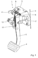
- eine dreidimensionale Ansicht einer erfindungsgemäßen Sicherheitseinrichtung in ihrer Normalstellung;
- Fig. 2
- einen vergrößerten Ausschnitt des Bereichs der Lagerung der Pedalachse aus Fig. 1 in einer teilweise geschnittenen Ansicht;
- Fig. 3
- eine seitliche Darstellung der erfindungsgemäßen Sicherheitseinrichtung in ihrer Normalstellung;
- Fig. 4
- eine Darstellung entsprechend Fig. 3, wobei das Pedal in einer Stellung nach Auslösung der erfindungsgemäßen Sicherheitseinrichtung gezeigt ist; und
- Fig. 5
- eine Draufsicht auf eine Darstellung der Sicherheitseinrichtung entsprechend der Fig. 2, wobei auf einer Seite ein Auslösehebel dargestellt ist und auf der anderen Seite nicht.
- Fig. 1
- a three-dimensional view of a safety device according to the invention in its normal position;
- Fig. 2
- an enlarged section of the area of the mounting of the pedal axis of Figure 1 in a partially sectioned view.
- Fig. 3
- a side view of the safety device according to the invention in its normal position;
- Fig. 4
- a representation corresponding to Figure 3, wherein the pedal is shown in a position after triggering the safety device according to the invention. and
- Fig. 5
- a plan view of an illustration of the safety device according to FIG. 2, wherein a release lever is shown on one side and not on the other side.
Bezug nehmend auf Fig. 1 ist eine Sicherheitseinrichtung 1 in
ihrer Normalstellung, also ohne daß eine Frontalkollision
stattfand, gezeigt. Eine solche Sicherheitseinrichtung dient
zur Lagerung von Pedalen 2 in Kraftfahrzeugen, mit einem Lagerbock
5, der in einem sich bei einer Frontalkollision des
Fahrzeugs deutlich in einen Fahrgastraum hinein verformenden
Wandbereich einer Spritz- oder Querwand 3 angeordnet ist. In
dem Lagerbock 5 ist eine Pedalachse 6 mindestens eines auf eine
Druckstange 7 einwirkenden, schwenkbaren Pedals 2, insbesondere
eines Bremspedals mit einer Trittplatte 4, gehaltert.1, a
Der Fig. 2, die einen vergrößterten Ausschnitt des Bereichs
der Lagerung der Pedalachse 6 aus Fig. 1 zeigt, und bei der
der Lagerbock im Bereich der Lagerung der Pedalachse geschnitten
ist, kann entnommen werden, daß die Pedalachse 6 im Lagerbock
5 in einer sich zumindest im wesentlichen horizontal erstreckenden
Führung 8 gehaltert ist. Diese Führung 8 weist in
horizontaler Richtung jeweils Begrenzungen 9 auf. In der in
Fig. 2 gezeigten Grundstellung ist die Pedalachse 6 wie auch
in Fig. 1 während des Normalbetriebes in einer in Vorwärtsfahrtrichtung
gesehen vorderen Position der Führung 8 fixiert.2, which is an enlarged section of the area
shows the mounting of the
Weiterhin ist in der Fig. 1 und Fig. 2 auch eine Rückzugfeder
12 gezeigt, die dazu dient, beim Lösen der Bremse, d.h. nachdem
die Belastung durch den Fuß des Fahrers vom Pedal 2 genommen
wurde, das Pedal 2 wieder in seine Grundstellung zu bringen
und so weiter keinen Druck auf die Druckstange 7 auszuüben.
Wird die Bremse aktiviert, wird über den Bremslichtschalter
13 das Bremslicht aktiviert.Furthermore, there is also a return spring in FIGS. 1 and 2
12, which serves to release the brake, i.e. after this
the load on the driver's foot taken from
In Fig. 3 ist eine der Fig. 1 und Fig. 2 entsprechende Anordnung
der Sicherheitseinrichtung 1 in ihrer Normalstellung in
einer seitlichen Ansicht gezeigt. Dabei kann insbesondere die
Lage der Pedalachse 6 gut erkannt werden. Um gerade die Lage
der Pedalachse 6 richtig erkennen zu können, wurde die Fixierung
11 bei dieser Darstellung nicht dargestellt.3 is an arrangement corresponding to FIGS. 1 and 2
the
Die Fixierung 11 kann dabei gemäß einer bevorzugten Ausführungsform
der Erfindung, was jedoch in den Figuren nicht dargestellt
ist, durch die relative Bewegung des Lagerbockes 5 zu
einem seine räumliche Lage auch bei einer Frontalkollision im
wesentlichen unverändert beibehaltenden Fahrzeugteil aufgehoben
werden. Das heißt also, daß die Fixierung an einem solchen
seine Lage bei einer Frontalkollision im wesentlichen beibehalten
Fahrzeugteil befestigt ist und dadurch aufgehoben wird,
daß sich der Lagerbock 5 bewegt und das feste Teil nicht.The
Eine der Fig. 3 entsprechende Darstellung, wobei jedoch die
Stellung des Pedals 2 gezeigt ist, nachdem die Fixierung 11
aufgehoben wurde, zeigt Fig. 4.A representation corresponding to FIG. 3, but with the
Position of the
Die in der Fig. 3 und Fig. 4 nicht dargestellte Fixierung 11
wird im Falle einer Frontalkollision aufgehoben, wodurch die
Pedalachse 6 in der Führung im Lagerbock 8 in Vorwärtsfahrtrichtung
gesehen nach hinten laufen kann. Gleichzeitig
schwenkt das Pedal 2 nach vorne aus. Als Fixpunkt ist dabei
dann die Anbindung des Pedals 2 an die Druckstange 7 anzusehen,
um die das Pedal 2 verschwenkt werden kann. Das Nachvornelaufen
des Pedals 2 kann dabei kraftlos erfolgen. Die Bewegung
des Pedals 2 nach dem Aufheben der Fixierung 11 nach einer
Frontalkollision ist in der Fig. 4 durch die Pfeile dargestellt.The
Mit der gezeigten Sicherheitseinrichtung 1 ist das Pedal 2 nun
nicht mehr fixiert, und somit kann es nicht zu Fußeinschnürungen
und Verklemmungen des Fahrzeuginsassen führen.With the
Des weiteren kann das Pedal 2 auch nicht einfach unkontrolliert
in den Fahrgastinnenraum hineinlaufen und damit zu Beeinträchtigungen
des Fahrzeuginsassen führen.Furthermore, the
Über die Veränderung der Länge der Führung 8 im Lagerbock 5
kann auch der dem Pedal 2 zur Verfügung stehende Weg nach vorne
verändert werden und so an die jeweiligen Fahrzeuggegebenheiten
angepaßt werden.About changing the length of the
Gemäß einer bevorzugten Ausführungsform der vorliegenden Erfindung ist das seine räumliche Lage bei einer Frontalkollision im wesentlichen unverändert beibehaltende Fahrzeugteil ein karosseriefestes Fahrzeugteil.According to a preferred embodiment of the present invention this is its spatial position in a head-on collision essentially unchanged vehicle part Body-fixed vehicle part.
Dabei kann dieses karosseriefeste Fahrzeugteil beispielsweise
ein Querträger sein oder auch ein Armaturentafelträger. Bei
beiden Fahrzeugteilen handelt es sich um die in Vorwärtsfahrtrichtung
gesehen hinter der dem Pedal 2 angeordnete Fahrzeugteile,
die bei einer Frontalkollision üblicherweise im wesentlichen
fahrzeugfest sind oder zumindest erst bei sehr starken
Unfällen beeinträchtigt werden.This vehicle body-fixed vehicle part, for example
be a cross member or a dashboard support. At
Both parts of the vehicle are in the forward direction
seen behind the vehicle parts arranged on the
Wie der Fig. 1 und Fig. 2 zu entnehmen ist, weist die sich zumindest
in horizontaler Richtung erstreckende Führung 8 im Lagerbock
5 im wesentlichen die Form eines Rechteckes aus. Ebenso
könnte sie aber auch als ein Langloch ausgebildet sein. As can be seen from FIGS. 1 and 2, it at least shows
Guide 8 extending in the horizontal direction in the
Durch Verändern der Länge der Führung 8, beispielsweise der
Länge des Langloches oder Rechteckes kann, wie schon beschrieben
wurde, der bei einer Frontalkollision zur Verfügung stehende
Pedalweg nach vorne verändert werden und so an die jeweiligen
Fahrzeuggegebenheiten angepaßt werden.By changing the length of the
Eine Gestaltung der Führung 8 in Form eines Langloches hat
sich deshalb als vorteilhaft erwiesen, da sie sehr einfach geschaffen
werden kann und darüber hinaus auch sehr einfach wieder
in eine dem Stand der Technik entsprechende Form zurückgebildet
werden kann, wenn eine Sicherheitseinrichtung 1 gemäß
der vorliegenden Erfindung nicht mehr gewünscht wird, denn
dann kann es beispielsweise einfach derart wieder verkleinert
werden, indem es aufgefüllt wird, und dann wieder die Form einer
üblichen Bohrung aufweist.Has a design of the
Gemäß einer bevorzugten Ausführungsform der Erfindung kann das
Vorlaufen der Pedalachse 6 in der Führung 8 des Lagerbockes 5
in Vorwärtsfahrtrichtung gesehen nach hinten bei einer Frontalkollision
auch durch eine zusätzliche Feder unterstützt
werden, so daß sich das Pedal 2 auch tatsächlich nach hinten
bewegt, sobald die Fixierung 11 aufgehoben wurde. Eine solche
Ausführungsform hat sich insbesondere dann als vorteilhaft erwiesen,
wenn andere Einheiten des Fahrzeuges die korrekte Auslösung
der erfindungsgemäßen Sicherheitseinrichtung 1 überwachen
und nur dann erkennen können, daß eine Aufhebung der Fixierung
11 stattgefunden hat, wenn das Pedal 2 sich in der
Führung 8 im Lagerbock 5 auch tatsächlich in Vorwärtsfahrtrichtung
gesehen nach hinten bewegt hat.According to a preferred embodiment of the invention, the
Advance of the
Es soll aber betont werden, daß eine Feder für eine erfindungsgemäße
Sicherheitseinrichtung 1 nicht unbedingt notwendig
ist, da das Pedal 2 nach dem Lösen der Fixierung 11 immer bewegt
werden kann, und daher ein Verklemmen des Fußes eines Insassen
nicht mehr möglich ist. Die bevorzugte Ausführungsform,
die eine Feder aufweist, soll nur beispielsweise bei einer
Meßaussage, die die Pedalposition mißt, verwendet werden, damit
dort richtige Aussagen gemacht werden können.But it should be emphasized that a spring for an
Wie nun der Fig. 1 und auch der Fig. 2 weiter zu entnehmen
ist, weist eine erfindungsgemäße Sicherheitseinrichtung 1 eine
Fixierung 11 der Pedalachse 6 derart auf, daß durch an dem bei
einer Frontalkollision im wesentlichen seine Position beibehaltende
Fahrzeugteil Auslösehebel 11 vorgesehen sind. So können
diese Auslösehebel 11 beispielsweise einen Anschlag an der
Karosserie aufweisen.As can now be seen in FIG. 1 and also in FIG. 2
has a
Bewegt sich nun der Pedallagerbock 5 bei einer Frontalkollision
durch die Verformung der Spritz- oder Querwand 3 in Richtung
des Fahrzeuginnenraumes, so kann die als Auslösehebel
ausgebildete Fixierung 11 der Pedalachse 6 dadurch ausgelöst
werden, daß sich das Fahrzeugteil, das seine räumliche Lage
auch bei einer Frontalkollision im wesentlichen unverändert
beibehält, relativ zum Pedallagerbock 5 bewegt. Dadurch wird
die Fixierung 11, die vorzugsweise Auslösehebel darstellen,
gelöst. Durch die beschriebene relative Bewegung können die an
einem fahrzeugfesten Teil angelenkten Auslösehebel beispielsweise
in einfacher Art und Weise weggeklappt werden.
Gemäß einer weiteren bevorzugten Ausführungsform der vorliegenden
Erfindung kann die Fixierung 11 jedoch auch hilfskraftbetätigt
ausgelöst werden. Dabei könnte es ebenso vorgesehen
sein, daß ein Sensor einen Frontalunfall mißt, und dann über
hydraulische, pneumatische oder auch pyrotechnische Mittel die
Fixierung 11 gelöst wird.According to a further preferred embodiment of the present
Invention, however, the
Betrachtet man nun nochmals die Fig. 3 und Fig. 4 genau, so
ist einfach zu erkennen, daß die Bremsstange 7 in der Grundstellung
wie auch in der Auslösestellung immer mit dem Pedal 2
in Verbindung bleibt. Bei dieser Fixierung 11 der Bremsstange
7 am Pedal 2 handelt es sich auch in der Auslösestellung um
einen Art Drehpunkt, um den das Pedal 2 bei einer Auslösung
pendeln kann. Somit wird ein Verklemmen eines Fußes eines
Fahrzeuginsassen verhindert.If we now consider FIGS. 3 and 4 again closely, see above
is easy to see that the
Dadurch daß die Bremsstange 7 nicht vom Pedal 2 gelöst wird,
und auch die Pedalachse 6 zumindest noch eine gewisse Lagerung,
wenn auch nicht eine an einem festen Punkt fixierte Lagerung,
aufweist, ist es weiterhin möglich, auf die Bremsstange
7 eine Kraft auszuüben. Dies ist zwar unter Umständen nicht
immer vollständig möglich, zumindest die Möglichkeit einer
Teilbremsung bleibt aber weiterhin erhalten.Because the
Findet nun bei einem Fahrzeug eine Frontalkollision statt,
würde die Sicherheitseinrichtung 1 gemäß der vorliegenden Erfindung
aktiviert werden. Nach dieser Frontalkollision wäre es
denkbar, daß das Fahrzeug auf die Gegenfahrbahn geschleudert
wird, sich auf einem Fahrbahnbereich befindet, auf dem noch
ein Verkehrfluß stattfindet, oder auf einen solchen zu gelangen
droht oder auch auf Fußgängerwege gelangen könnte. Dabei
kann es sehr wichtig sein, daß das Fahrzeug trotz des Auslösens
der Sicherheitseinrichtung 1, die ein Verklemmen des Fahrerfußes
verhindert, noch gebremst werden kann und das Fahrzeug
gebremst werden kann, noch bevor es beispielsweise auf
die Gegenfahrbahn weiter rollt. Dadurch kann unter Umständen
eine zweite Kollision verhindert werden.If there is a frontal collision in a vehicle,
would the
Somit kann bei der erfindungsgemäßen Sicherheitseinrichtung 1
nicht nur die Sicherheit für die Fahrzeuginsassen selbst, sondern
auch die Sicherheit für andere Verkehrsteilnehmer erhöht
werden.Thus, in the
Die vorliegende erfindungsgemäße Sicherheitseinrichtung 1 hat
sich insbesondere auch deshalb als vorteilhaft erwiesen, da
sie durch eine sehr einfache konstruktive Gestaltung ein sehr
hohes Maß an Sicherheit für die Fahrzeuginsassen und außenstehende
Unfallbeteiligte bietet. The
Die Sicherheitseinrichtung 1 kann gemäß der vorliegenden Erfindung
derart ausgebildet sein, daß der Pedallagerbock 5, wie
auch bisher bei Pedalwerken des Standes der Technik, üblicherweise
aus Kunststoff ausgebildet ist. Dadurch kann die bisher
verwendete innovative Leichtbautechnik des Pedallagerbocks 5
auch bei einer erfindungsgemäßen Sicherheitseinrichtung 1 verwendet
werden, wodurch neben einer einfachen Konstruktion auch
keine unnötigen Erhöhungen des Gewichts des Fahrzeugs und damit
der Betriebskosten durch die Sicherheitseinrichtung 1 die
Folge sind.The
Darüber hinaus kann das Pedal 2, und dabei insbesondere das
Bremspedal, wie üblicherweise als ein Zweischalenpedal ausgebildet
sein. Dies bedeutet, daß das üblicherweise schon verwendete
Pedal 2, nämlich ein aus zwei tiefgezogenen Stahlhalbschalen
gebildetes Pedal 2 auch bei einer Anordnung gemäß der
vorliegenden Erfindung weiter verwendet werden kann. Damit
liegen die Vorteile dieses sich als sehr torsionssteif erwiesenen
Pedals 2 auch in einer erfindungsgemäßen Anordnung weiter
vor.In addition, the
In der Fig. 5 ist noch eine Draufsicht auf eine Darstellung
der Sicherheitseinrichtung 1 entsprechend der Fig. 2 gezeigt,
wobei auf einer Seite ein Auslösehebel 11 dargestellt ist, der
das Langloch 8 schließt. Die andere Seite ist ohne Auslösehebel
11 dargestllt und zwar nur mit der Pedallagerache 6 in dem
Langloch 8. Der Auslösehebel 11 ist, wie der Darstellung in
Fig. 5 zu entnehmen ist, in seiner das Langloch 8 schließenden
Stellung so angeordnet, daß er in Richtung der Fahrgastzelle
gesehen vor der Pedallagerachse 6 angeordnet ist. Findet nun
ein Auslösen des Hebels 11 durch eine Verformung der Stirnwand
3 statt, dann wird der Hebel 11 herausgezogen und dadurch der
Wandbereich 14 abgebrochen. Somit kann über die Stärke des
Wandbereichs 14 die Auslösekraft der Fixierung 11 verändert
werden.5 is a top view of an illustration
the
Claims (12)
dadurch gekennzeichnet, daß die Pedalachse (6) im Lagerbock (5) in einer sich zumindest im wesentlichen horizontal erstreckenden Führung (8) gehaltert ist, wobei die Führung (8) in horizontaler Richtung jeweils Begrenzungen (9) aufweist; und
die Pedalachse (6) während des Normalbetriebes in einer in Vorwärtsfahrtrichtung gesehen vorderen Position der Führung (8) fixiert ist und diese Fixierung (11) bei einer Frontalkollision aufgehoben wird.Safety device for the storage of pedals in motor vehicles, in particular passenger vehicles, with a bearing block which is arranged in a wall region of a dashboard or transverse wall which noticeably deforms into a passenger compartment in the event of a frontal collision, wherein in the bearing block at least one pedal axis on one Push rod acting, pivotable pedal, in particular a brake pedal, is held,
characterized in that the pedal axis (6) is held in the bearing block (5) in an at least substantially horizontally extending guide (8), the guide (8) each having limits (9) in the horizontal direction; and
the pedal axis (6) is fixed during normal operation in a forward position of the guide (8) when viewed in the forward direction and this fixation (11) is released in the event of a head-on collision.
dadurch gekennzeichnet, daß die Fixierung (11) durch eine relative Bewegung des Lagerbockes (5) zu einem seine räumliche Lage auch bei einer Frontalkollision im wesentlichen unverändert beibehaltenden Fahrzeugteil aufgehoben wird.Safety device according to claim 1,
characterized in that the fixation (11) is released by a relative movement of the bearing block (5) to a vehicle part which maintains its spatial position essentially unchanged even in a head-on collision.
dadurch gekennzeichnet, daß das seine räumliche Lage bei einer Frontalkollision im wesentlichen unverändert beibehaltende Fahrzeugteil karosseriefest ist.Safety device according to claim 1,
characterized in that the vehicle part which remains essentially unchanged in its spatial position in the event of a frontal collision is fixed to the body.
dadurch gekennzeichnet, daß das karosseriefeste Fahrzeugteil ein Querträger ist.Safety device according to claim 3,
characterized in that the body-fixed vehicle part is a cross member.
dadurch gekennzeichnet, daß das karosseriefeste Fahrzeugteil ein Armaturentafelträger ist.Safety device according to claim 3,
characterized in that the body-fixed vehicle part is a dashboard support.
dadurch gekennzeichnet, daß die sich zumindest im wesentlichen horizontal erstrekkende Führung (8) im Lagerbock (5) im wesentlichen die Form eines Langloches aufweist.Safety device according to claim 1,
characterized in that the at least substantially horizontally extending guide (8) in the bearing block (5) has essentially the shape of an elongated hole.
dadurch gekennzeichnet, daß ein Bewegen der Pedalachse (6) in der Führung (8) in Vorwärtsfahrtrichtung gesehen nach hinten bei einer Frontalkollision durch eine Feder unterstützt wird.Safety device according to claim 1,
characterized in that a movement of the pedal axis (6) in the guide (8), when viewed in the forward direction, is assisted in the event of a head-on collision by a spring.
dadurch gekennzeichnet, daß die Fixierung (11) der Pedalachse (6) durch an dem bei einer Frontalkollision im wesentlichen seine Position beibehaltenden Fahrzeugteil befestigte Auslösehebel erfolgt.Safety device according to claim 1,
characterized in that the fixing (11) of the pedal axle (6) takes place by means of release levers fastened to the vehicle part which essentially maintains its position in the event of a frontal collision.
dadurch gekennzeichnet, daß die Fixierung (11) durch die relative Bewegung des Pedallagerbockes (5) zum bei einer Frontalkollision im wesentlichen seine Position beibehaltenden Fahrzeugteil ausgelöst werden. Safety device according to claim 8,
characterized in that the fixation (11) is triggered by the relative movement of the pedal bracket (5) to the vehicle part essentially maintaining its position in a head-on collision.
dadurch gekennzeichnet, daß die Fixierung (11) hilfskraftbetätigt ausgelöst wird.Safety device according to claim 1,
characterized in that the fixation (11) is triggered by auxiliary power.
dadurch gekennzeichnet, daß der Pedallagerbock (5) aus Kunststoff ausgebildet ist.Safety device according to claim 1,
characterized in that the pedal bracket (5) is made of plastic.
dadurch gekennzeichnet, daß das Pedal (2) als ein Zweischalenpedal ausgebildet ist.Safety device according to claim 1,
characterized in that the pedal (2) is designed as a two-shell pedal.
Applications Claiming Priority (2)
| Application Number | Priority Date | Filing Date | Title |
|---|---|---|---|
| DE10022813A DE10022813C5 (en) | 2000-05-10 | 2000-05-10 | Safety device for the storage of pedals |
| DE10022813 | 2000-05-10 |
Publications (3)
| Publication Number | Publication Date |
|---|---|
| EP1153805A2 true EP1153805A2 (en) | 2001-11-14 |
| EP1153805A3 EP1153805A3 (en) | 2004-01-07 |
| EP1153805B1 EP1153805B1 (en) | 2008-01-16 |
Family
ID=7641475
Family Applications (1)
| Application Number | Title | Priority Date | Filing Date |
|---|---|---|---|
| EP01109739A Expired - Lifetime EP1153805B1 (en) | 2000-05-10 | 2001-04-20 | Safety device for bearing of pedals |
Country Status (5)
| Country | Link |
|---|---|
| US (1) | US6786109B2 (en) |
| EP (1) | EP1153805B1 (en) |
| JP (1) | JP2002002460A (en) |
| DE (2) | DE10022813C5 (en) |
| ES (1) | ES2299448T3 (en) |
Cited By (2)
| Publication number | Priority date | Publication date | Assignee | Title |
|---|---|---|---|---|
| EP1557330A2 (en) * | 2004-01-20 | 2005-07-27 | Batz, S. Coop. | Pedal with an anti-collision safety mechanism |
| CN102205835A (en) * | 2010-03-31 | 2011-10-05 | 本田技研工业株式会社 | Pedal device |
Families Citing this family (23)
| Publication number | Priority date | Publication date | Assignee | Title |
|---|---|---|---|---|
| FR2832969B1 (en) * | 2001-11-30 | 2004-01-02 | Renault | DEVICE FOR MOUNTING A PEDAL ON A VEHICLE |
| DE10222106A1 (en) | 2002-05-17 | 2004-01-22 | Fico Cables, S.A., Rubi | Pedal security system |
| US7744645B2 (en) * | 2003-09-29 | 2010-06-29 | Medtronic Vascular, Inc. | Laminated drug-polymer coated stent with dipped and cured layers |
| DE10354668B4 (en) * | 2003-11-22 | 2007-02-22 | EDSCHA Betätigungssysteme GmbH | pedal bearing |
| SE527696C2 (en) * | 2004-01-26 | 2006-05-16 | Teleflex Automotive Sweden Ab | Pedal rack assembly |
| CA2495351A1 (en) * | 2004-01-29 | 2005-07-29 | Intier Automotive Closures Inc. | Variable ratio brake pedal |
| US20080047386A1 (en) * | 2006-08-07 | 2008-02-28 | Ridgway Jason R | Automotive foot pedal assembly |
| EP2078644B1 (en) | 2008-01-08 | 2013-11-06 | GM Global Technology Operations LLC | Safety pedal system |
| US7987743B2 (en) * | 2008-12-19 | 2011-08-02 | Ventra Group, Inc. | Positive release crash pedal mechanism |
| FR2944115B1 (en) | 2009-04-07 | 2015-06-05 | Coutier Moulage Gen Ind | AUTOMOTIVE VEHICLE PEDAL WITH SAFETY DEVICE. |
| DE102009034783B4 (en) | 2009-07-25 | 2017-07-13 | Volkswagen Ag | Foot pedal system on motor vehicles |
| JP2013502344A (en) * | 2009-08-18 | 2013-01-24 | ケイエスアール テクノロジーズ カンパニー | Brake pedal assembly with non-contact sensor |
| BR112012019497A2 (en) | 2010-02-04 | 2017-06-27 | Ksr Tech Co | electromechanical brake apparatus |
| US8806976B2 (en) | 2010-02-04 | 2014-08-19 | Ksr Technologies Co. | Brake pedal assembly having non-contacting sensor |
| DE102010025566A1 (en) * | 2010-06-29 | 2011-12-29 | Gm Global Technology Operations Llc (N.D.Ges.D. Staates Delaware) | Arrangement for releasing foot pedals of motor car during vigorous front crash, has deformable trip lever deformed against stop element at steering cross beam and pushing rod to shear pin out of aperture of pedal lever during crash |
| EP2578454B1 (en) * | 2011-10-06 | 2014-12-10 | Volvo Car Corporation | Safety arrangement for vehicle pedal |
| CN104245432B (en) | 2012-03-15 | 2017-03-15 | Ksr智财控股公司 | There is the pedal assembly of pedal arm release member |
| KR101509990B1 (en) * | 2013-11-27 | 2015-04-07 | 현대자동차주식회사 | Apparatus for reducing effort of clutch pedal |
| KR101526723B1 (en) * | 2013-12-03 | 2015-06-05 | 현대자동차주식회사 | Position adjustable pedal |
| US9889826B2 (en) | 2014-02-19 | 2018-02-13 | Ventra Group Co. | Variable ratio brake pedal |
| DE102015208203A1 (en) * | 2015-05-04 | 2016-11-10 | Bayerische Motoren Werke Aktiengesellschaft | Pedal arrangement for a motor vehicle and hereby equipped motor vehicle |
| USD920860S1 (en) * | 2019-05-03 | 2021-06-01 | Ventra Group Co. | Automotive brake pedal arm |
| US20230234527A1 (en) * | 2022-01-24 | 2023-07-27 | Ventra Group, Co. | Pedal assembly with pyrotechnic release |
Citations (10)
| Publication number | Priority date | Publication date | Assignee | Title |
|---|---|---|---|---|
| DE4409235A1 (en) | 1993-03-31 | 1994-10-06 | Volkswagen Ag | Safety foot control linkage for a motor vehicle |
| DE4409324A1 (en) | 1993-03-31 | 1994-10-06 | Volkswagen Ag | Safety foot control linkage for a motor vehicle |
| DE19501859A1 (en) | 1995-01-23 | 1996-07-25 | Volkswagen Ag | Safety arrangement for a motor vehicle |
| DE19501680A1 (en) | 1995-01-20 | 1996-08-08 | Schmidt Gmbh R | Foot pedal unit for vehicle |
| WO1997028029A1 (en) | 1996-01-30 | 1997-08-07 | Ab Volvo | Method for activation of a safety arrangement in a vehicle |
| DE19631212C1 (en) | 1996-08-02 | 1997-12-18 | Daimler Benz Ag | Accelerator pedal unit |
| DE19617372C1 (en) | 1996-04-30 | 1998-01-02 | Lucas Ind Plc | Braking pedal device for road vehicle |
| EP0827874A2 (en) | 1996-08-07 | 1998-03-11 | Adam Opel Ag | Arrangement for supporting a pedal |
| DE19652014A1 (en) | 1996-12-13 | 1998-06-18 | Opel Adam Ag | Pedal mounting for motor vehicle |
| DE19737114A1 (en) | 1997-08-03 | 1999-05-06 | Scharwaechter Ed Gmbh | Safety device for the storage of pedals in motor vehicles |
Family Cites Families (15)
| Publication number | Priority date | Publication date | Assignee | Title |
|---|---|---|---|---|
| US3388610A (en) * | 1966-05-31 | 1968-06-18 | Val R. Pyle | Brake pedal linkage |
| US3803941A (en) * | 1972-10-20 | 1974-04-16 | Yoshikawa Seisakusho Kk | Brake lever for a bicycle |
| FR2272871B1 (en) * | 1974-05-27 | 1976-12-24 | Citroen Sa | |
| US4875385A (en) * | 1986-08-18 | 1989-10-24 | Sitrin Gabriel M | Control pedal apparatus for a motor vehicle |
| US5460061A (en) * | 1993-09-17 | 1995-10-24 | Comfort Pedals, Inc. | Adjustable control pedal apparatus |
| DE19529347A1 (en) * | 1995-08-09 | 1997-02-20 | Hs Tech & Design | Detachable pedal-mounting in motor vehicle |
| JP3454014B2 (en) * | 1995-08-31 | 2003-10-06 | トヨタ自動車株式会社 | Vehicle pedal support structure |
| JP3269372B2 (en) | 1996-02-13 | 2002-03-25 | トヨタ自動車株式会社 | Vehicle pedal structure |
| JPH09290714A (en) * | 1996-04-30 | 1997-11-11 | Toyota Motor Corp | Pedal supporting structure for vehicle |
| JP3454041B2 (en) | 1996-10-08 | 2003-10-06 | スズキ株式会社 | Brake pedal support structure |
| DE19706427A1 (en) * | 1997-02-19 | 1998-08-20 | Itt Mfg Enterprises Inc | Pressure fluid accumulator |
| DE19733512C2 (en) * | 1997-08-03 | 2003-12-11 | Scharwaechter Gmbh Co Kg | safety device |
| JP2000177546A (en) * | 1998-12-17 | 2000-06-27 | Otsuka Koki Co Ltd | Foot parking brake device |
| DE19921392C2 (en) * | 1999-05-10 | 2001-08-02 | Zf Lemfoerder Metallwaren Ag | Actuator for the brake system of a motor vehicle |
| GB2353009B (en) * | 2000-04-27 | 2001-07-11 | Dura Automotive Ltd | Collapsible pedal box |
-
2000
- 2000-05-10 DE DE10022813A patent/DE10022813C5/en not_active Expired - Fee Related
-
2001
- 2001-04-20 DE DE50113488T patent/DE50113488D1/en not_active Expired - Lifetime
- 2001-04-20 ES ES01109739T patent/ES2299448T3/en not_active Expired - Lifetime
- 2001-04-20 EP EP01109739A patent/EP1153805B1/en not_active Expired - Lifetime
- 2001-05-10 JP JP2001140755A patent/JP2002002460A/en active Pending
- 2001-05-10 US US09/852,285 patent/US6786109B2/en not_active Expired - Fee Related
Patent Citations (10)
| Publication number | Priority date | Publication date | Assignee | Title |
|---|---|---|---|---|
| DE4409235A1 (en) | 1993-03-31 | 1994-10-06 | Volkswagen Ag | Safety foot control linkage for a motor vehicle |
| DE4409324A1 (en) | 1993-03-31 | 1994-10-06 | Volkswagen Ag | Safety foot control linkage for a motor vehicle |
| DE19501680A1 (en) | 1995-01-20 | 1996-08-08 | Schmidt Gmbh R | Foot pedal unit for vehicle |
| DE19501859A1 (en) | 1995-01-23 | 1996-07-25 | Volkswagen Ag | Safety arrangement for a motor vehicle |
| WO1997028029A1 (en) | 1996-01-30 | 1997-08-07 | Ab Volvo | Method for activation of a safety arrangement in a vehicle |
| DE19617372C1 (en) | 1996-04-30 | 1998-01-02 | Lucas Ind Plc | Braking pedal device for road vehicle |
| DE19631212C1 (en) | 1996-08-02 | 1997-12-18 | Daimler Benz Ag | Accelerator pedal unit |
| EP0827874A2 (en) | 1996-08-07 | 1998-03-11 | Adam Opel Ag | Arrangement for supporting a pedal |
| DE19652014A1 (en) | 1996-12-13 | 1998-06-18 | Opel Adam Ag | Pedal mounting for motor vehicle |
| DE19737114A1 (en) | 1997-08-03 | 1999-05-06 | Scharwaechter Ed Gmbh | Safety device for the storage of pedals in motor vehicles |
Cited By (4)
| Publication number | Priority date | Publication date | Assignee | Title |
|---|---|---|---|---|
| EP1557330A2 (en) * | 2004-01-20 | 2005-07-27 | Batz, S. Coop. | Pedal with an anti-collision safety mechanism |
| EP1557330A3 (en) * | 2004-01-20 | 2005-12-21 | Batz, S. Coop. | Pedal with an anti-collision safety mechanism |
| CN102205835A (en) * | 2010-03-31 | 2011-10-05 | 本田技研工业株式会社 | Pedal device |
| CN102205835B (en) * | 2010-03-31 | 2014-02-26 | 本田技研工业株式会社 | Pedal device |
Also Published As
| Publication number | Publication date |
|---|---|
| JP2002002460A (en) | 2002-01-09 |
| DE50113488D1 (en) | 2008-03-06 |
| DE10022813A1 (en) | 2001-11-22 |
| US6786109B2 (en) | 2004-09-07 |
| US20020007693A1 (en) | 2002-01-24 |
| EP1153805B1 (en) | 2008-01-16 |
| ES2299448T3 (en) | 2008-06-01 |
| DE10022813C5 (en) | 2008-07-24 |
| EP1153805A3 (en) | 2004-01-07 |
| DE10022813B4 (en) | 2004-02-19 |
Similar Documents
| Publication | Publication Date | Title |
|---|---|---|
| DE10022813C5 (en) | Safety device for the storage of pedals | |
| EP0804352B1 (en) | Motor vehicle safety arrangement | |
| DE4409235B4 (en) | Safety foot lever mechanism for a motor vehicle | |
| EP0893310B1 (en) | Pedal arrangement in a motor vehicle | |
| DE19631212C1 (en) | Accelerator pedal unit | |
| DE60317089T2 (en) | MATCHABLE PEDAL HOUSING | |
| DE102012007889A1 (en) | Protective device of a motor vehicle | |
| DE60012117T2 (en) | Support structure for a motor vehicle pedal assembly | |
| DE69934001T2 (en) | System for expressing the brake pedal in the event of a collision | |
| DE19601800A1 (en) | Safety device for vehicle | |
| DE102005042281A1 (en) | Pedal mounting bracket arrangement for passenger car, has plastic bearing block with side walls, and pedal supported at walls that form reference break lines through retaining bearing axis, where lines run between walls and block | |
| DE60003191T2 (en) | IMPROVED SHOCK ABSORBING SYSTEM IN MOTOR VEHICLES | |
| DE102011082148B4 (en) | Pedal arrangement with a safety device having a separating wedge | |
| EP0836968A1 (en) | Arrrangement for the front end of a vehicle | |
| DE102015210296B4 (en) | Crash device for a motor vehicle | |
| DE19803406B4 (en) | Safety device for a motor vehicle | |
| DE102018000314B4 (en) | Steering column for a motor vehicle, in particular for a passenger car | |
| DE10258627B4 (en) | Motor vehicle with a front hood | |
| DE69920242T2 (en) | VEHICLE DASHBOARD ARRANGEMENT | |
| EP0897851A2 (en) | Deformable cab for lorries | |
| DE4314416C1 (en) | Automotive safety steering gear | |
| DE102016218597B4 (en) | Pedal assembly for a motor vehicle | |
| EP1637421B1 (en) | Brake actuating device for a vehicle | |
| DE102009008838B4 (en) | Steering column for a motor vehicle | |
| DE102010015540A1 (en) | Safety arrangement for motor vehicle, comprises pedal, which is pivotally mounted on pedal axle through connectable linkage |
Legal Events
| Date | Code | Title | Description |
|---|---|---|---|
| PUAI | Public reference made under article 153(3) epc to a published international application that has entered the european phase |
Free format text: ORIGINAL CODE: 0009012 |
|
| AK | Designated contracting states |
Kind code of ref document: A2 Designated state(s): AT BE CH CY DE DK ES FI FR GB GR IE IT LI LU MC NL PT SE TR |
|
| AX | Request for extension of the european patent |
Free format text: AL;LT;LV;MK;RO;SI |
|
| PUAL | Search report despatched |
Free format text: ORIGINAL CODE: 0009013 |
|
| AK | Designated contracting states |
Kind code of ref document: A3 Designated state(s): AT BE CH CY DE DK ES FI FR GB GR IE IT LI LU MC NL PT SE TR |
|
| AX | Request for extension of the european patent |
Extension state: AL LT LV MK RO SI |
|
| 17P | Request for examination filed |
Effective date: 20031203 |
|
| 17Q | First examination report despatched |
Effective date: 20040304 |
|
| AKX | Designation fees paid |
Designated state(s): DE ES FR GB IT SE |
|
| RAP1 | Party data changed (applicant data changed or rights of an application transferred) |
Owner name: DAIMLERCHRYSLER AG |
|
| GRAP | Despatch of communication of intention to grant a patent |
Free format text: ORIGINAL CODE: EPIDOSNIGR1 |
|
| GRAS | Grant fee paid |
Free format text: ORIGINAL CODE: EPIDOSNIGR3 |
|
| GRAA | (expected) grant |
Free format text: ORIGINAL CODE: 0009210 |
|
| RAP1 | Party data changed (applicant data changed or rights of an application transferred) |
Owner name: DAIMLER AG |
|
| AK | Designated contracting states |
Kind code of ref document: B1 Designated state(s): DE ES FR GB IT SE |
|
| REG | Reference to a national code |
Ref country code: GB Ref legal event code: FG4D Free format text: NOT ENGLISH |
|
| GBT | Gb: translation of ep patent filed (gb section 77(6)(a)/1977) |
Effective date: 20080213 |
|
| REF | Corresponds to: |
Ref document number: 50113488 Country of ref document: DE Date of ref document: 20080306 Kind code of ref document: P |
|
| REG | Reference to a national code |
Ref country code: SE Ref legal event code: TRGR |
|
| REG | Reference to a national code |
Ref country code: ES Ref legal event code: FG2A Ref document number: 2299448 Country of ref document: ES Kind code of ref document: T3 |
|
| ET | Fr: translation filed | ||
| PLBE | No opposition filed within time limit |
Free format text: ORIGINAL CODE: 0009261 |
|
| STAA | Information on the status of an ep patent application or granted ep patent |
Free format text: STATUS: NO OPPOSITION FILED WITHIN TIME LIMIT |
|
| 26N | No opposition filed |
Effective date: 20081017 |
|
| REG | Reference to a national code |
Ref country code: DE Ref legal event code: R081 Ref document number: 50113488 Country of ref document: DE Owner name: AUTOLIV DEVELOPMENT AB, SE Free format text: FORMER OWNER: DAIMLER AG, 70327 STUTTGART, DE Effective date: 20120302 |
|
| PGFP | Annual fee paid to national office [announced via postgrant information from national office to epo] |
Ref country code: SE Payment date: 20120427 Year of fee payment: 12 Ref country code: FR Payment date: 20120611 Year of fee payment: 12 Ref country code: GB Payment date: 20120430 Year of fee payment: 12 |
|
| PGFP | Annual fee paid to national office [announced via postgrant information from national office to epo] |
Ref country code: IT Payment date: 20120420 Year of fee payment: 12 |
|
| PGFP | Annual fee paid to national office [announced via postgrant information from national office to epo] |
Ref country code: ES Payment date: 20120530 Year of fee payment: 12 |
|
| REG | Reference to a national code |
Ref country code: SE Ref legal event code: EUG |
|
| GBPC | Gb: european patent ceased through non-payment of renewal fee |
Effective date: 20130420 |
|
| PG25 | Lapsed in a contracting state [announced via postgrant information from national office to epo] |
Ref country code: GB Free format text: LAPSE BECAUSE OF NON-PAYMENT OF DUE FEES Effective date: 20130420 Ref country code: SE Free format text: LAPSE BECAUSE OF NON-PAYMENT OF DUE FEES Effective date: 20130421 |
|
| REG | Reference to a national code |
Ref country code: FR Ref legal event code: ST Effective date: 20131231 |
|
| PG25 | Lapsed in a contracting state [announced via postgrant information from national office to epo] |
Ref country code: FR Free format text: LAPSE BECAUSE OF NON-PAYMENT OF DUE FEES Effective date: 20130430 Ref country code: IT Free format text: LAPSE BECAUSE OF NON-PAYMENT OF DUE FEES Effective date: 20130420 |
|
| REG | Reference to a national code |
Ref country code: ES Ref legal event code: FD2A Effective date: 20140715 |
|
| PG25 | Lapsed in a contracting state [announced via postgrant information from national office to epo] |
Ref country code: ES Free format text: LAPSE BECAUSE OF NON-PAYMENT OF DUE FEES Effective date: 20130421 |
|
| PGFP | Annual fee paid to national office [announced via postgrant information from national office to epo] |
Ref country code: DE Payment date: 20160421 Year of fee payment: 16 |
|
| REG | Reference to a national code |
Ref country code: DE Ref legal event code: R119 Ref document number: 50113488 Country of ref document: DE |
|
| PG25 | Lapsed in a contracting state [announced via postgrant information from national office to epo] |
Ref country code: DE Free format text: LAPSE BECAUSE OF NON-PAYMENT OF DUE FEES Effective date: 20171103 |