EP1152251A2 - Verfahren und Anlage zur Magnetfluss-Schätzung in einem elektromagnetischen Aktuator zur Steuerung eines Maschinenventils - Google Patents
Verfahren und Anlage zur Magnetfluss-Schätzung in einem elektromagnetischen Aktuator zur Steuerung eines Maschinenventils Download PDFInfo
- Publication number
- EP1152251A2 EP1152251A2 EP01110859A EP01110859A EP1152251A2 EP 1152251 A2 EP1152251 A2 EP 1152251A2 EP 01110859 A EP01110859 A EP 01110859A EP 01110859 A EP01110859 A EP 01110859A EP 1152251 A2 EP1152251 A2 EP 1152251A2
- Authority
- EP
- European Patent Office
- Prior art keywords
- magnetic flux
- coil
- electromagnet
- time
- magnetic
- Prior art date
- Legal status (The legal status is an assumption and is not a legal conclusion. Google has not performed a legal analysis and makes no representation as to the accuracy of the status listed.)
- Granted
Links
Images


Classifications
-
- F—MECHANICAL ENGINEERING; LIGHTING; HEATING; WEAPONS; BLASTING
- F01—MACHINES OR ENGINES IN GENERAL; ENGINE PLANTS IN GENERAL; STEAM ENGINES
- F01L—CYCLICALLY OPERATING VALVES FOR MACHINES OR ENGINES
- F01L9/00—Valve-gear or valve arrangements actuated non-mechanically
- F01L9/20—Valve-gear or valve arrangements actuated non-mechanically by electric means
- F01L9/21—Valve-gear or valve arrangements actuated non-mechanically by electric means actuated by solenoids
- F01L2009/2105—Valve-gear or valve arrangements actuated non-mechanically by electric means actuated by solenoids comprising two or more coils
- F01L2009/2109—The armature being articulated perpendicularly to the coils axes
Definitions
- the present invention relates to a method of estimating magnetic flux in an electromagnetic actuator for controlling an engine valve.
- Electromagnetic actuators definitely have various advantages, by enabling optimum control of each valve in any operating condition of the engine, unlike conventional mechanical actuators (typically, camshafts) which call for defining a valve lift profile representing no more than an acceptable compromise for all possible operating conditions of the engine.
- An electromagnetic valve actuator for an internal combustion engine of the type described above normally comprises at least one electromagnet for moving an actuator body of ferromagnetic material and connected mechanically to the respective valve stem; and, to apply a particular law of motion to the valve, a control unit drives the electromagnet with time-variable current to move the actuator body accordingly.
- the present invention also relates to a device for estimating magnetic flux in an electromagnetic actuator for controlling an engine valve.
- a device for estimating magnetic flux in an electromagnetic actuator for controlling an engine valve as claimed in Claim 6.
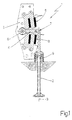
- Number 1 in Figure 1 indicates as a whole an electromagnetic actuator (of the type described in Italian Patent Application BO99A000443 filed on 4 August 1999) connected to an intake or exhaust valve 2 of a known internal combustion engine to move valve 2, along a longitudinal axis 3 of the valve, between a known closed position (not shown) and a known fully-open position (not shown).
- an electromagnetic actuator of the type described in Italian Patent Application BO99A000443 filed on 4 August 1999
- an intake or exhaust valve 2 of a known internal combustion engine to move valve 2, along a longitudinal axis 3 of the valve, between a known closed position (not shown) and a known fully-open position (not shown).
- Electromagnetic actuator 1 comprises an oscillating arm 4 made at least partly of ferromagnetic material, and which has a first end hinged to a support 5 to oscillate about an axis 6 of rotation perpendicular to the longitudinal axis 3 of valve 2; and a second end connected by a hinge 7 to the top end of valve 2. Electromagnetic actuator 1 also comprises two electromagnets 8 fitted in fixed positions to support 5 and located on opposite sides of oscillating arm 4; and a spring 9 fitted to valve 2 and for keeping oscillating arm 4 in an intermediate position (shown in Figure 1) in which oscillating arm 4 is equidistant from the pole pieces 10 of the two electromagnets 8.
- electromagnets 8 are controlled by a control unit 11 to alternately or simultaneously exert a magnetic force of attraction on oscillating arm 4 to rotate it about axis 6 of rotation and so move valve 2, along longitudinal axis 3, between said fully-open and closed positions (not shown). More specifically, valve 2 is set to the closed position (not shown) when oscillating arm 4 rests on the bottom electromagnet 8; is set to the fully-open position (not shown) when oscillating arm 4 rests on the top electromagnet 8; and is set to a partially open position when electromagnets 8 are both deenergized and oscillating arm 4 is maintained in said intermediate position (shown in Figure 1) by spring 9.
- Control unit 11 feedback controls the position of oscillating arm 4, i.e. of valve 2, in substantially known manner on the basis of the operating conditions of the engine. More specifically, as shown in Figure 2, control unit 11 comprises a reference generating block 12; a calculating block 13; a drive block 14 for supplying electromagnets 8 with time-variable current; and an estimating block 15 for estimating in substantially real time the position x(t) and speed v(t) of oscillating arm 4.
- reference generating block 12 receives a number of parameters indicating the operating conditions of the engine (e.g. load, speed, throttle position, drive shaft angular position, cooling liquid temperature), and supplies calculating block 13 with a target (i.e. desired) value x R (t) of the position of oscillating arm 4 (and hence of valve 2).
- a target i.e. desired value x R (t) of the position of oscillating arm 4 (and hence of valve 2).
- calculating block 13 processes and supplies drive block 14 with a control signal z(t) for driving electromagnets 8.
- calculating block 13 also processes control signal z(t) on the basis of an estimated value v(t) of the speed of oscillating arm 4 received from estimating block 15.
- reference generating block 12 supplies calculating block 13 with both a target value x R (t) of the position of oscillating arm 4, and a target value v R (t) of the speed of oscillating arm 4.
- drive block 14 supplies both electromagnets 8, each of which comprises a respective magnetic core 16 fitted to a corresponding coil 17 to move oscillating arm 4 as commanded by calculating block 13.
- Estimating block 15 reads values - explained in detail later on - from both drive block 14 and the two electromagnets 8 to calculate an estimated value x(t) of the position and an estimated value v(t) of the speed of oscillating arm 4.
- Oscillating arm 4 is located between the pole pieces 10 of the two electromagnets 8, which are fitted to support 5 in fixed positions a fixed distance D apart, so that the estimated value x(t) of the position of oscillating arm 4 can be calculated directly, by means of a simple algebraic sum operation, from an estimated value d(t) of the distance between a given point of oscillating arm 4 and a corresponding point of either one of electromagnets 8.
- the estimated value v(t) of the speed of oscillating arm 4 can be calculated directly from an estimated value of the speed between a given point of oscillating arm 4 and a corresponding point of either one of electromagnets 8.
- estimating block 15 calculates two estimated values d 1 (t), d 2 (t) of the distance between a given point of oscillating arm 4 and a corresponding point of each of the two electromagnets 8; and, from the two estimated values d 1 (t), d 2 (t), estimating block 15 calculates two values x 1 (t), x 2 (t), which normally differ from each other owing to measuring noise and errors. In a preferred embodiment, estimating block 15 calculates the mean of the two values x 1 (t), x 2 (t), possibly weighted according to the accuracy attributed to each value x(t).
- estimating block 15 calculates two estimated values of the speed between a given point of oscillating arm 4 and a corresponding point of each of the two electromagnets 8; and, from the two estimated speed values, estimating block 15 calculates two values v 1 (t), v 2 (t), which normally differ from each other owing to measuring noise and errors. In a preferred embodiment, estimating block 15 calculates the mean of the two values v 1 (t), v 2 (t), possibly weighted according to the accuracy attributed to each value v(t).
- estimating block 15 calculates an estimated value d(t) of the distance between a given point of oscillating arm 4 and a corresponding point of electromagnet 8, and an estimated value of the speed between a given point of oscillating arm 4 and a corresponding point of electromagnet 8, will now be described with particular reference to Figure 4 showing one electromagnet 8.
- magnetic circuit 18 connected to coil 17 is defined by the core 16 of ferromagnetic material of electromagnet 8, by oscillating arm 4 of ferromagnetic material, and by the gap 19 between core 16 and oscillating arm 4.
- total reluctance R generally depends on both the position x(t) of oscillating arm 4 (i.e. the size of gap 19, which, minus a constant, equals the position x(t) of oscillating arm 4) and the value of flux ⁇ (t). With the exception of negligible errors (i.e.
- the value of gap reluctance R o can be calculated, given the value of current i(t), which is easily measured using an ammeter 20; given the value of N (which is fixed and depends on the construction characteristics of coil 17); given the value of flux ⁇ (t); and given the relationship between iron reluctance R fe and flux ⁇ (known from the construction characteristics of magnetic circuit 18 and the magnetic characteristics of the material used, or easily determined by tests) .
- Constants K 0 , K 1 , K 2 , K 3 can be determined experimentally by means of a series of measurements of magnetic circuit 18.
- position x(t) of oscillating arm 4 can therefore be calculated relatively easily. And, given the value of position x(t) of oscillating arm 4, the value of speed v(t) of oscillating arm 4 can be calculated by means of a straightforward time derivation operation of position x(t).
- flux ⁇ (t) can be calculated by measuring the current i(t) circulating through coil 17 using known ammeter 20, by measuring the voltage v(t) applied to the terminals of coil 17 using a known voltmeter 21, and given the value (easily measured) of resistance RES of coil 17.
- the conventional instant 0 is so selected as to accurately determine the value of the flux ⁇ (0) at instant 0, and, in particular, is normally selected within a time interval in which no current flows in coil 17, so that flux ⁇ is substantially zero (the effect of any residual magnetization is negligible), or is selected at a given position of oscillating arm 4 (typically, when oscillating arm 4 rests on pole pieces 10 of electromagnet 8) at which the value of position x and therefore of flux ⁇ is known.
- the above method of calculating flux ⁇ (t) is fairly accurate and fast (i.e. with no delays), but poses several problems due to the voltage v(t) applied to the terminals of coil 17 normally being generated by a switching amplifier integrated in drive block 14 and therefore varying continually between three values (+V supply , 0, -V supply ), two of which (+V supply and -V supply ) have a relatively high value which is therefore difficult to measure accurately without the aid of relatively complex, high-cost measuring circuits.
- the above method of calculating flux ⁇ (t) calls for continually reading the current i(t) circulating through coil 17, and for knowing at all times the value of resistance RES of coil 17, which, as known, varies alongside a variation in the temperature of coil 17.
- one embodiment only employs one, while an alternative embodiment employs both and uses the mean of the results of both methods (possibly weighted according to the accuracy attributed to each), or uses one result to check the other (a major difference between the two results probably indicates an estimating error).
- control unit 11 feedback controls the value of flux ⁇ (t), in which case, the flux ⁇ (t) measurement is fundamental (feedback control of the value of flux ⁇ (t) is normally applied as an alternative to feedback controlling the value of current i(t) circulating in coil 17).
- estimating block 15 operates, as described above, with both electromagnets 8, so as to use the estimate relative to one electromagnet 8 when the other is deenergized.
- estimating block 15 calculates the mean - possibly weighted according to the accuracy attributed to each value x(t) - of the two values x(t) calculated relative to both electromagnets 8 (position x estimated with respect to one electromagnet 8 is normally more accurate when oscillating arm 4 is relatively close to pole pieces 10 of electromagnet 8).
Landscapes
- Engineering & Computer Science (AREA)
- Mechanical Engineering (AREA)
- General Engineering & Computer Science (AREA)
- Valve Device For Special Equipments (AREA)
- Magnetically Actuated Valves (AREA)
Applications Claiming Priority (2)
| Application Number | Priority Date | Filing Date | Title |
|---|---|---|---|
| ITBO000248 | 2000-05-04 | ||
| IT2000BO000248A IT1321182B1 (it) | 2000-05-04 | 2000-05-04 | Metodo e dispositivo per la stima del flusso magnetico in unazionatore elettromagnetico per il comando di una valvola di un motore |
Publications (3)
| Publication Number | Publication Date |
|---|---|
| EP1152251A2 true EP1152251A2 (de) | 2001-11-07 |
| EP1152251A3 EP1152251A3 (de) | 2002-06-12 |
| EP1152251B1 EP1152251B1 (de) | 2009-07-22 |
Family
ID=11438442
Family Applications (1)
| Application Number | Title | Priority Date | Filing Date |
|---|---|---|---|
| EP01110859A Expired - Lifetime EP1152251B1 (de) | 2000-05-04 | 2001-05-04 | Verfahren und Anlage zur Magnetfluss-Schätzung in einem elektromagnetischen Aktuator zur Steuerung eines Maschinenventils |
Country Status (6)
| Country | Link |
|---|---|
| US (1) | US6591204B2 (de) |
| EP (1) | EP1152251B1 (de) |
| BR (1) | BR0101919A (de) |
| DE (1) | DE60139289D1 (de) |
| ES (1) | ES2328788T3 (de) |
| IT (1) | IT1321182B1 (de) |
Cited By (1)
| Publication number | Priority date | Publication date | Assignee | Title |
|---|---|---|---|---|
| EP1231361A3 (de) * | 2001-02-13 | 2003-01-08 | MAGNETI MARELLI POWERTRAIN S.p.A. | Verfahren zur Bestimmung der Magnetisierung eines elektromagnetischen Ventilsteuerungsaktuators |
Families Citing this family (4)
| Publication number | Priority date | Publication date | Assignee | Title |
|---|---|---|---|---|
| ITBO20010760A1 (it) * | 2001-12-14 | 2003-06-16 | Magneti Marelli Powertrain Spa | Metodo per la stima della posizione e della velocita' di un corpo attuatore in un azionatore elettromagnetico per il comando di una valvola |
| US7248041B2 (en) * | 2003-07-28 | 2007-07-24 | Cummins, Inc. | Device and method for measuring transient magnetic performance |
| US20050076866A1 (en) * | 2003-10-14 | 2005-04-14 | Hopper Mark L. | Electromechanical valve actuator |
| US7089895B2 (en) * | 2005-01-13 | 2006-08-15 | Motorola, Inc. | Valve operation in an internal combustion engine |
Citations (6)
| Publication number | Priority date | Publication date | Assignee | Title |
|---|---|---|---|---|
| JPH05280315A (ja) * | 1992-03-31 | 1993-10-26 | Isuzu Motors Ltd | 電磁駆動バルブ |
| US5442515A (en) * | 1991-12-10 | 1995-08-15 | Clark Equipment Company | Method and apparatus for controlling the current through a magnetic coil |
| WO1997017561A1 (en) * | 1994-11-09 | 1997-05-15 | Aura Systems, Inc. | Hinged armature electromagnetically actuated valve |
| JPH09320841A (ja) * | 1996-05-28 | 1997-12-12 | Toyota Motor Corp | 電磁アクチュエータ制御装置 |
| US5960753A (en) * | 1995-05-17 | 1999-10-05 | Sturman; Oded E. | Hydraulic actuator for an internal combustion engine |
| EP0959479A2 (de) * | 1998-04-28 | 1999-11-24 | Siemens Automotive Corporation | Verfahren zur Regelung der Geschwindigkeit eines Ankers in einem elektromagnetischem Aktuator |
Family Cites Families (2)
| Publication number | Priority date | Publication date | Assignee | Title |
|---|---|---|---|---|
| US3689828A (en) * | 1970-03-17 | 1972-09-05 | Hitachi Ltd | Manually controlled case depth measuring instrument with indicators to guide its use |
| US6249418B1 (en) * | 1999-01-27 | 2001-06-19 | Gary Bergstrom | System for control of an electromagnetic actuator |
-
2000
- 2000-05-04 IT IT2000BO000248A patent/IT1321182B1/it active
-
2001
- 2001-05-02 BR BR0101919-8A patent/BR0101919A/pt not_active IP Right Cessation
- 2001-05-04 DE DE60139289T patent/DE60139289D1/de not_active Expired - Lifetime
- 2001-05-04 US US09/848,553 patent/US6591204B2/en not_active Expired - Fee Related
- 2001-05-04 ES ES01110859T patent/ES2328788T3/es not_active Expired - Lifetime
- 2001-05-04 EP EP01110859A patent/EP1152251B1/de not_active Expired - Lifetime
Patent Citations (6)
| Publication number | Priority date | Publication date | Assignee | Title |
|---|---|---|---|---|
| US5442515A (en) * | 1991-12-10 | 1995-08-15 | Clark Equipment Company | Method and apparatus for controlling the current through a magnetic coil |
| JPH05280315A (ja) * | 1992-03-31 | 1993-10-26 | Isuzu Motors Ltd | 電磁駆動バルブ |
| WO1997017561A1 (en) * | 1994-11-09 | 1997-05-15 | Aura Systems, Inc. | Hinged armature electromagnetically actuated valve |
| US5960753A (en) * | 1995-05-17 | 1999-10-05 | Sturman; Oded E. | Hydraulic actuator for an internal combustion engine |
| JPH09320841A (ja) * | 1996-05-28 | 1997-12-12 | Toyota Motor Corp | 電磁アクチュエータ制御装置 |
| EP0959479A2 (de) * | 1998-04-28 | 1999-11-24 | Siemens Automotive Corporation | Verfahren zur Regelung der Geschwindigkeit eines Ankers in einem elektromagnetischem Aktuator |
Non-Patent Citations (2)
| Title |
|---|
| PATENT ABSTRACTS OF JAPAN vol. 018, no. 059 (M-1552), 31 January 1994 (1994-01-31) & JP 05 280315 A (ISUZU MOTORS LTD), 26 October 1993 (1993-10-26) * |
| PATENT ABSTRACTS OF JAPAN vol. 1998, no. 04, 31 March 1998 (1998-03-31) -& JP 09 320841 A (TOYOTA MOTOR CORP), 12 December 1997 (1997-12-12) * |
Cited By (1)
| Publication number | Priority date | Publication date | Assignee | Title |
|---|---|---|---|---|
| EP1231361A3 (de) * | 2001-02-13 | 2003-01-08 | MAGNETI MARELLI POWERTRAIN S.p.A. | Verfahren zur Bestimmung der Magnetisierung eines elektromagnetischen Ventilsteuerungsaktuators |
Also Published As
| Publication number | Publication date |
|---|---|
| US20020084777A1 (en) | 2002-07-04 |
| ITBO20000248A1 (it) | 2001-11-04 |
| IT1321182B1 (it) | 2003-12-30 |
| US6591204B2 (en) | 2003-07-08 |
| BR0101919A (pt) | 2001-12-26 |
| DE60139289D1 (de) | 2009-09-03 |
| EP1152251B1 (de) | 2009-07-22 |
| ES2328788T3 (es) | 2009-11-18 |
| EP1152251A3 (de) | 2002-06-12 |
Similar Documents
| Publication | Publication Date | Title |
|---|---|---|
| EP1152129B1 (de) | Verfahren und Vorrichtung zur Lagebestimmung eines Ankers in einem elektromagnetischen Aktuator zur Steuerung eines Motorventils | |
| US6397797B1 (en) | Method of controlling valve landing in a camless engine | |
| US6683775B2 (en) | Control method for an electromagnetic actuator for the control of an engine valve | |
| EP1152251A2 (de) | Verfahren und Anlage zur Magnetfluss-Schätzung in einem elektromagnetischen Aktuator zur Steuerung eines Maschinenventils | |
| US6659422B2 (en) | Control method for an electromagnetic actuator for the control of a valve of an engine from a rest condition | |
| US6798636B2 (en) | Method of estimating the effect of the parasitic currents in an electromagnetic actuator for the control of an engine valve | |
| EP1319807B1 (de) | Verfahren zum Abschätzen der Position und Geschwindigkeit eines Ankers in einem elektromagnetischen Aktor zur Steuerung eines Motorventils | |
| JP3614092B2 (ja) | 電磁駆動弁のバルブクリアランス推定装置及び制御装置 | |
| EP1231361B1 (de) | Verfahren zur Bestimmung der Magnetisierung eines elektromagnetischen Ventilsteuerungsaktuators | |
| EP1271570B1 (de) | Regelverfahren eines elektromagnetischen Aktuators zur Steuerung eines Motorventils vom Positionsanschlag heraus | |
| US6340007B2 (en) | Method for estimating the end-of-stroke positions of moving members of electromagnetic actuators for the actuation of intake and exhaust valves in internal combustion engines | |
| JP2003284369A (ja) | Emvaアマチュアの位置および速度を推定する方法 | |
| US20070097589A1 (en) | Method of preadjusting an electromagnetic actuator |
Legal Events
| Date | Code | Title | Description |
|---|---|---|---|
| PUAI | Public reference made under article 153(3) epc to a published international application that has entered the european phase |
Free format text: ORIGINAL CODE: 0009012 |
|
| AK | Designated contracting states |
Kind code of ref document: A2 Designated state(s): AT BE CH CY DE DK ES FI FR GB GR IE IT LI LU MC NL PT SE TR |
|
| AX | Request for extension of the european patent |
Free format text: AL;LT;LV;MK;RO;SI |
|
| PUAL | Search report despatched |
Free format text: ORIGINAL CODE: 0009013 |
|
| AK | Designated contracting states |
Kind code of ref document: A3 Designated state(s): AT BE CH CY DE DK ES FI FR GB GR IE IT LI LU MC NL PT SE TR |
|
| AX | Request for extension of the european patent |
Free format text: AL;LT;LV;MK;RO;SI |
|
| 17P | Request for examination filed |
Effective date: 20021210 |
|
| AKX | Designation fees paid |
Designated state(s): DE ES FR GB SE |
|
| 17Q | First examination report despatched |
Effective date: 20070531 |
|
| GRAP | Despatch of communication of intention to grant a patent |
Free format text: ORIGINAL CODE: EPIDOSNIGR1 |
|
| RAP1 | Party data changed (applicant data changed or rights of an application transferred) |
Owner name: MAGNETI MARELLI POWERTRAIN S.P.A. |
|
| RAP1 | Party data changed (applicant data changed or rights of an application transferred) |
Owner name: MAGNETI MARELLI HOLDING S.P.A. |
|
| RAP1 | Party data changed (applicant data changed or rights of an application transferred) |
Owner name: MAGNETI MARELLI S.P.A. |
|
| GRAS | Grant fee paid |
Free format text: ORIGINAL CODE: EPIDOSNIGR3 |
|
| GRAA | (expected) grant |
Free format text: ORIGINAL CODE: 0009210 |
|
| AK | Designated contracting states |
Kind code of ref document: B1 Designated state(s): DE ES FR GB SE |
|
| REG | Reference to a national code |
Ref country code: GB Ref legal event code: FG4D |
|
| REF | Corresponds to: |
Ref document number: 60139289 Country of ref document: DE Date of ref document: 20090903 Kind code of ref document: P |
|
| REG | Reference to a national code |
Ref country code: SE Ref legal event code: TRGR |
|
| REG | Reference to a national code |
Ref country code: ES Ref legal event code: FG2A Ref document number: 2328788 Country of ref document: ES Kind code of ref document: T3 |
|
| PLBE | No opposition filed within time limit |
Free format text: ORIGINAL CODE: 0009261 |
|
| STAA | Information on the status of an ep patent application or granted ep patent |
Free format text: STATUS: NO OPPOSITION FILED WITHIN TIME LIMIT |
|
| 26N | No opposition filed |
Effective date: 20100423 |
|
| PGFP | Annual fee paid to national office [announced via postgrant information from national office to epo] |
Ref country code: ES Payment date: 20100611 Year of fee payment: 10 |
|
| PGFP | Annual fee paid to national office [announced via postgrant information from national office to epo] |
Ref country code: SE Payment date: 20100531 Year of fee payment: 10 Ref country code: GB Payment date: 20100527 Year of fee payment: 10 |
|
| PGFP | Annual fee paid to national office [announced via postgrant information from national office to epo] |
Ref country code: FR Payment date: 20110621 Year of fee payment: 11 |
|
| PGFP | Annual fee paid to national office [announced via postgrant information from national office to epo] |
Ref country code: DE Payment date: 20110505 Year of fee payment: 11 |
|
| REG | Reference to a national code |
Ref country code: SE Ref legal event code: EUG |
|
| GBPC | Gb: european patent ceased through non-payment of renewal fee |
Effective date: 20110504 |
|
| PG25 | Lapsed in a contracting state [announced via postgrant information from national office to epo] |
Ref country code: GB Free format text: LAPSE BECAUSE OF NON-PAYMENT OF DUE FEES Effective date: 20110504 |
|
| REG | Reference to a national code |
Ref country code: ES Ref legal event code: FD2A Effective date: 20121116 |
|
| PG25 | Lapsed in a contracting state [announced via postgrant information from national office to epo] |
Ref country code: ES Free format text: LAPSE BECAUSE OF NON-PAYMENT OF DUE FEES Effective date: 20110505 |
|
| REG | Reference to a national code |
Ref country code: FR Ref legal event code: ST Effective date: 20130131 |
|
| REG | Reference to a national code |
Ref country code: DE Ref legal event code: R119 Ref document number: 60139289 Country of ref document: DE Effective date: 20121201 |
|
| PG25 | Lapsed in a contracting state [announced via postgrant information from national office to epo] |
Ref country code: SE Free format text: LAPSE BECAUSE OF NON-PAYMENT OF DUE FEES Effective date: 20110505 Ref country code: FR Free format text: LAPSE BECAUSE OF NON-PAYMENT OF DUE FEES Effective date: 20120531 |
|
| PG25 | Lapsed in a contracting state [announced via postgrant information from national office to epo] |
Ref country code: DE Free format text: LAPSE BECAUSE OF NON-PAYMENT OF DUE FEES Effective date: 20121201 |