EP1152108A2 - Hand-free access system for a motor vehicle - Google Patents
Hand-free access system for a motor vehicle Download PDFInfo
- Publication number
- EP1152108A2 EP1152108A2 EP01401095A EP01401095A EP1152108A2 EP 1152108 A2 EP1152108 A2 EP 1152108A2 EP 01401095 A EP01401095 A EP 01401095A EP 01401095 A EP01401095 A EP 01401095A EP 1152108 A2 EP1152108 A2 EP 1152108A2
- Authority
- EP
- European Patent Office
- Prior art keywords
- signal
- identification device
- bit
- piracy
- vehicle
- Prior art date
- Legal status (The legal status is an assumption and is not a legal conclusion. Google has not performed a legal analysis and makes no representation as to the accuracy of the status listed.)
- Granted
Links
Images


Classifications
-
- G—PHYSICS
- G07—CHECKING-DEVICES
- G07C—TIME OR ATTENDANCE REGISTERS; REGISTERING OR INDICATING THE WORKING OF MACHINES; GENERATING RANDOM NUMBERS; VOTING OR LOTTERY APPARATUS; ARRANGEMENTS, SYSTEMS OR APPARATUS FOR CHECKING NOT PROVIDED FOR ELSEWHERE
- G07C9/00—Individual registration on entry or exit
- G07C9/00174—Electronically operated locks; Circuits therefor; Nonmechanical keys therefor, e.g. passive or active electrical keys or other data carriers without mechanical keys
- G07C9/00309—Electronically operated locks; Circuits therefor; Nonmechanical keys therefor, e.g. passive or active electrical keys or other data carriers without mechanical keys operated with bidirectional data transmission between data carrier and locks
- G07C2009/00555—Electronically operated locks; Circuits therefor; Nonmechanical keys therefor, e.g. passive or active electrical keys or other data carriers without mechanical keys operated with bidirectional data transmission between data carrier and locks comprising means to detect or avoid relay attacks
-
- G—PHYSICS
- G07—CHECKING-DEVICES
- G07C—TIME OR ATTENDANCE REGISTERS; REGISTERING OR INDICATING THE WORKING OF MACHINES; GENERATING RANDOM NUMBERS; VOTING OR LOTTERY APPARATUS; ARRANGEMENTS, SYSTEMS OR APPARATUS FOR CHECKING NOT PROVIDED FOR ELSEWHERE
- G07C9/00—Individual registration on entry or exit
- G07C9/00174—Electronically operated locks; Circuits therefor; Nonmechanical keys therefor, e.g. passive or active electrical keys or other data carriers without mechanical keys
- G07C2009/00753—Electronically operated locks; Circuits therefor; Nonmechanical keys therefor, e.g. passive or active electrical keys or other data carriers without mechanical keys operated by active electrical keys
- G07C2009/00769—Electronically operated locks; Circuits therefor; Nonmechanical keys therefor, e.g. passive or active electrical keys or other data carriers without mechanical keys operated by active electrical keys with data transmission performed by wireless means
- G07C2009/00793—Electronically operated locks; Circuits therefor; Nonmechanical keys therefor, e.g. passive or active electrical keys or other data carriers without mechanical keys operated by active electrical keys with data transmission performed by wireless means by Hertzian waves
-
- G—PHYSICS
- G07—CHECKING-DEVICES
- G07C—TIME OR ATTENDANCE REGISTERS; REGISTERING OR INDICATING THE WORKING OF MACHINES; GENERATING RANDOM NUMBERS; VOTING OR LOTTERY APPARATUS; ARRANGEMENTS, SYSTEMS OR APPARATUS FOR CHECKING NOT PROVIDED FOR ELSEWHERE
- G07C2209/00—Indexing scheme relating to groups G07C9/00 - G07C9/38
- G07C2209/06—Involving synchronization or resynchronization between transmitter and receiver; reordering of codes
-
- G—PHYSICS
- G07—CHECKING-DEVICES
- G07C—TIME OR ATTENDANCE REGISTERS; REGISTERING OR INDICATING THE WORKING OF MACHINES; GENERATING RANDOM NUMBERS; VOTING OR LOTTERY APPARATUS; ARRANGEMENTS, SYSTEMS OR APPARATUS FOR CHECKING NOT PROVIDED FOR ELSEWHERE
- G07C2209/00—Indexing scheme relating to groups G07C9/00 - G07C9/38
- G07C2209/60—Indexing scheme relating to groups G07C9/00174 - G07C9/00944
- G07C2209/63—Comprising locating means for detecting the position of the data carrier, i.e. within the vehicle or within a certain distance from the vehicle
Definitions
- the present invention relates to a so-called hand access system free for motor vehicle, i.e. a system of wireless communication allowing entry into the vehicle without key.
- This system can also be applied to hands-free starting of the vehicle, i.e. when starting without a key.
- Such a system generally includes a device identification intended to be worn by a user and capable of establishing wireless two-way remote communication with a unit control unit on board the vehicle to authenticate the user and order locking means / unlocking the door locks when the user has been recognized as authentic.
- Communication protocol initialization can be activated by operating the exterior door handle, to hands-free access, or by pressing a start button, in hands-free start mode.
- the system is able to establish said two-way communication when the identification device is located at a distance less than a predetermined limit distance from the vehicle, generally of the order of a few meters, to avoid, on the one hand, interference with other signal sources from the environment, and, on the other hand, to avoid the functioning of the system at a distance such that the user is too far from the vehicle to be aware of the operations carried out by said system.
- a such a system allows communication only at very short distance from the vehicle in the order of a few cm.
- Another commonly used system proposed is to use low frequency carrier waves, around 125 kHz for communication from the vehicle to the identification device, and ultra high carrier waves frequency, for example of the order of 434 or 868 MHz, for the area Europe, and 315 or 902 MHz for the USA zone.
- the identification device must include a battery to power its own electronic circuits. To minimize consumption electric, we can provide, for example, that the device identification is dormant for 9 ms and awake 1 ms, during periods of 10 ms.
- FIG. 1 of the accompanying drawings there is shown a example of an already known encryption system.
- a vehicle V which comprises in its central unit a memory 1 containing a secret key K and a number generator 2, the generated random numbers R having, for example, a length of 56 bits.
- This random number R is transmitted towards the identification device I, as indicated by arrow 3.
- this same random number R is mixed with the key secret K following a complex associative function f, in a mixer 4 which is connected to its input to memory 1 and to the generator of random numbers 2.
- Mixer 4 outputs a signal representative of the mixture of the secret key K and the random number R, namely the signal f (R, K).
- This signal is stored in a memory 5 connected to the output of mixer 4.
- This signal is sent to the device of identification I, in the form of a signal of length by 28-bit example, as indicated by arrow 6.
- the signal f (R, K) is mixed again with the secret key K in a mixer 7, which is connected at its input to memories 1 and 5 above.
- This mixer 7 mixes the two signals according to a function complex associative g.
- Vehicle V then stores in a memory 8 connected to the mixer output 7 the signal representative of the mixture, namely the signal g (R, f, K).
- the same secret key K is stored in a memory 11 and a mixer 14 having the same associative function f receives as input the secret key provided by the memory 11 of the identification device I and the random number R received by the identification device from the vehicle.
- the identification device I stores the signal at the mixer output 14 in a memory 15 and compare this signal in a comparator 16 with the signal received according to arrow 6 from vehicle V. If the two signals are not identical, subject to the time of hardware and signal transmission delay in the area of authorized transmission, the identification device interrupts the communication as unauthorized. On the other hand, if the two signals match, the signal is mixed in a mixer 17 with the secret key provided by memory 11 of the device identification I, following the same associative function g above.
- the mixer 17 output signal is stored in memory 18 of the identification device to be then sent to the vehicle according to arrow 9 in the form of a signal having a length by 20 bit example.
- the signal received by arrow 9 is compared with the signal received from the vehicle memory 8 in a comparator 10. If these two signals match, subject to delays due to hardware response time and signal transmission in the authorized zone, the rest of the communication is authorized and the unit vehicle center may, if necessary, order the condemnation or unlocking of the door locks of the vehicle.
- another encryption protocol could be used to secure data transmission.
- This signal 21 sent by the vehicle is received by a coil 22 of the relay box 20, which is connected to a receiver 23 at 125 kHz.
- This receiver 23 is connected to a transmitter at broadband at high frequency, of the order of several MHz.
- the transmitter 24 transmits via its antenna 25, as represented by the arrow 26, towards a second relay box 30, which is carried by another hacker who closely follows user U.
- the exchange of information between the two relay boxes 20 and 30 being carried out at very high frequency, it communication is possible from a long distance.
- the second relay box 30 includes an antenna 31 for receiving the signal 26 emitted by the relay box 20.
- the antenna 31 is connected to a broadband receiver at the same frequency as transmitter 24 of the first relay box 20.
- the signal thus received is retransmitted at low frequency at 125 kHz by a transmitter 33 which is connected to a coil 34 to send a signal 35 to the device identification I which conforms to signal 21 emitted by the vehicle.
- the signal 35 being the repetition of the authentic signal of the vehicle, the identification device I will recognize it and in turn issue its response signal 36, said response signal 36 being sent at high frequency and received by an antenna 37 of the second relay box 30, by example at 434 MHz.
- the antenna 37 is connected to a receiver 38, which goes convert the signal at 434 MHz to a signal at a different frequency, for example at 315 MHz.
- the signal is then transmitted by a transmitter at broadband 39 via an antenna 40 to the first relay box 20, this difference in frequency being necessary for the different signals do not interfere with each other.
- the frequency of signal 41 sent back by the second relay box 30 is different both the frequency of signal 26 and signal 36.
- This signal 41 is received by an antenna 27 of the first relay box 20, said antenna 27 being connected to a broadband receiver 28 of the same frequency as the transmitter 39.
- the receiver 28 is connected to a transmitter 29 which transforms the 315 MHz signal into a 434 MHz signal which is sent via the antenna 42 of the first relay box 20 to the vehicle V, as represented by the zigzag arrow 43.
- the hackers use relay boxes having broadband links, for example greater than 50 MHz, which is possible because pirate systems do not have to respect regulations; additional transit time due to distance can be of the order of a few nanoseconds, which is negligible compared to the necessary time constants for normal transmission allowed.
- the total communication can be of the order of 20 to 40 ms, and the duration total operation of the system to trigger the unlocking or locking electric locks can be of the order of 100 ms.
- one solution could be to measure the propagation time of UHF radio waves, comparing this measured time with a time predetermined corresponding to a communication in an area limited allowed around the vehicle.
- a time predetermined corresponding to a communication in an area limited allowed around the vehicle For example, to detect the time delay due to distance, compared to communication time overall, it is necessary to have broad bandwidth, which corresponds to a rapid communication rate, for example of in the range of 20 to 40 Mb / s. With such a communication rate, it is necessary to operate at very high frequency, for example at 2.4 GHz. But to measure very short times, it is necessary to have a very high bandwidth, which comes up against applicable regulations that severely limit bandwidths allowed, to avoid saturation of the environment with waves electromagnetic.
- the object of the invention is to eliminate the aforementioned drawbacks and to propose a so-called hands-free access system for a motor vehicle, allowing to detect a hacking of the system, in particular by through relay boxes, taking into account the time of propagation of the signal between the vehicle and the identification device.
- the invention relates to an access system called hands free for motor vehicle, comprising a device identification intended to be worn by a user and capable of establishing wireless two-way remote communication with a unit control unit on board the vehicle to authenticate the user and order locking means / unlocking the door locks when the user has been recognized as authentic, said system being capable of establishing said two-way communication when the identification device is located at a distance less than a predetermined limit distance from the vehicle, characterized in that said central unit is able to generate, during communication, an anti-piracy bit stream, each bit of said train being transmitted to the identification device under the form of a radio frequency signal representative of said bit, so that when the identification device receives said signal, the latter is re-issued by the identification device with a delay time greater than or equal to the useful transmission time of the bit, and that reception by the central control unit of said re-emitted signal triggers the central unit transmitting the signal representative of the next bit in said train, the number of bits transmitted or received from said train, being counted by a
- Transmission time means useful "the transmission time of the binary information of said bit compared the total time of the cell with which said bit is associated, which includes generally said useful time and a time of silence to allow the reception of the signal re-emitted by the identification device during said time of silence.
- said predetermined threshold value is given by a time window which corresponds to the total duration theoretical emission of the anti-piracy bit stream, when the identification device is at a distance less than or equal to the predetermined limit distance.
- This time window is a constant precise generated for example by an oscillator controlled by quartz associated with a counter controlled by the micro-controller which indicates the number of periods to count.
- the central control unit is suitable to determine said hacking attempt when the total number of bits of the anti-piracy train was not issued or received by the central processing unit command in said window.
- the central unit can include in memory a double entry correspondence table, namely the number of bits transmitted and the corresponding actual transmission time, for output the actual distance between the identification device and the central unit, the data from said table having been acquired beforehand by experimentation and which can be periodically updated, when the user wearing the identification device is seated on the driver's seat of the vehicle, the distance from the identification device to the central unit of the vehicle then being substantially constant.
- a double entry correspondence table namely the number of bits transmitted and the corresponding actual transmission time
- the counting of the number of bits transmitted is stopped when the central unit detects the reception of the last bit of the train anti-piracy.
- the identification device comprises a line to analog delay to retransmit the signal received from the vehicle to the vehicle with a predetermined delay time.
- the central control unit includes a radio carrier wave oscillator frequency, connected to a phase modulator, which is controlled by the Anti-piracy bit stream generated by the central unit of the vehicle.
- the anti-piracy bit stream is generated by the central processing unit after the data transmission authentication methods encrypted to the identification device.
- the identification device may include a phase inverter to selectively reverse the phase of the signal representative of the bits anti-piracy received by the identification device from the vehicle, said inverter being controlled, for each bit of anti-piracy, by an encrypted digital authentication response signal of the identification device, at a slower rate than that of the anti-piracy bit stream.
- the central unit of the vehicle comprising a phase demodulator for demodulating the signal received by the vehicle from the identification device, a logic gate Exclusive OR whose inputs are respectively linked to said audit phase demodulator and a digital signal retarder, said retarder being able to delay by bit useful time each bit of the train of anti-piracy generated by the central unit, said logic gate being able to output a digital signal representative of the signal encrypted response from the identification device.
- the signal delivered in output of the aforementioned exclusive OR logic gate is compared by the unit central to an encrypted digital authentication signal generated by the central unit, in order to authenticate the identification device.
- the exit from said door exclusive OR logic is connected to an input of a second door exclusive OR logic whose other input receives a digital signal encrypted authentication generated by the central unit, in order to deliver at output a signal representative of the successive time offsets of each bit of the anti-piracy train, this last signal being received at the input of an integrator to sum the response times linked at each anti-piracy bit shift slot, the output of said integrator being connected to a comparator to compare said sum response time with a predetermined time limit value, beyond which a hacking attempt is detected.
- the signal from of the identification device is received by the central unit and transmitted to the input of an envelope detector to detect the rising edge of said signal, the detection of this rising edge being able to trigger, of a hand, incrementing the number of bits by one and, on the other hand, the transmission of the next bit in the anti-piracy bit stream, after a predetermined duration which corresponds to a bit time useful possibly increased by additional time to avoid any interference between the transmission and reception of the signal by the unit central.
- the central unit includes a modulator says all or nothing to switch the central unit in the transmission or reception mode of signals to or from identification device, said all-or-nothing modulator being controlled by the detection of the rising edge of the signal received in origin of the identification device.
- the identification device comprises a receiver for receiving low cadence wake-up signals, receiver successively comprising a static envelope detector low threshold radio frequency and low frequency amplifier.
- the useful bit time can be between 50 and 200 ns.
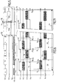
- the motor vehicle V has in its central unit a microcontroller 50, which is usually in a semi-sleep state or waiting for an alarm clock.
- a microcontroller 50 which is usually in a semi-sleep state or waiting for an alarm clock.
- an activation signal is sent to the microcontroller 50, as indicated by arrow 51.
- the microcontroller sends a general power signal, such as represented by arrow 52, to supply the various components central unit electronics.
- the microcontroller 50 generates a series of signals at low cadence sk, for example of the order of 2 to 100 Kb / s on line V5.
- the data carried on line V5 is successively an awakening signal, a signal representative of a number random R with a length for example of 56 bits, a signal representative of the function f (R, K) of a length for example of 28 bits, and of a signal representative of service data s, for example with a length of 100 to 5,000 bits, for example data on the maintenance, vehicle adjustment, etc. (see Figure 5).
- Line V5 is connected to a transmitter 53 to transmit signals via an antenna 54 towards the identification device I as represented by the arrow E.
- the transmitter 53 includes, as best seen in FIG. 4, a oscillator 55 to generate an ultra high carrier wave frequency, said oscillator being supplied by line 52.
- the oscillator 55 is connected to a phase modulator 56, which in turn is connected to a all-or-nothing modulator 57, the latter having an input connected to the line V5 and its output connected to the above-mentioned antenna 54.
- the phase modulator When issuing data at low rate sk on line V5, the phase modulator is inactive.
- the all or nothing modulator 57 is intended for alternately allow the transmission of a signal and the reception of a signal by the unit center of the vehicle, as explained below.
- the amplitude of the transmitted signal is of the order of 2 V rms.
- the signal emitted E is received by an antenna 100 of the device identification I with an attenuation of the order of -40 dBm, which represents an attenuation coefficient of 100 times, i.e. the signal received by the identification device has an amplitude of around 20 mV.
- the antenna 100 is connected to a radio frequency filter 101 (only shown in Figure 4) to eliminate the spurious frequencies.
- the output of filter 101 is connected to a branching, on the one hand, to a receiver at low cadence and at low consumption 102 and, on the other hand, to a delay line analog 103. Low speed signals sk are not transmitted via delay line 103, but mainly via the receiver 102. As best seen in FIG.
- the receiver 102 includes successively a radio frequency envelope detector 104 for reconstitute the signals at low cadence on line I5, which correspond to those of line V5.
- Detector output envelope 104 is connected to a low frequency amplifier 105, of which the output is connected in parallel, on the one hand, to a sequence decoder awakening 106 and, on the other hand, to a microcontroller 107 of the device identification I via line 108.
- the decoder 106 is supplied with permanently by the battery of the identification device.
- the awakening data are decoded by the decoder 106, in order to send a wake-up command to the microcontroller 107, at the output of the decoder 106.
- the microcontroller 107 then awakens all the other components of the identification device. So the data following, namely the signals R, f and s, are transmitted directly to the microcontroller 107 via the parallel line 108.
- the microcontroller 50 of vehicle V After transmission of the service data s, the microcontroller 50 of vehicle V generates anti-piracy bits h at the slow rate sk of the microprocessor, said anti-piracy bits being received by a 58 random binary sequence generator buffer output the high-speed anti-piracy bits fk, on a line V7.
- the output of buffer memory 58 is connected to a branch, on the one hand, with the phase modulator 56 for modulate in phase the carrier wave generated by the oscillator 55, and on the other hand, with a digital timer with a useful bit time 59, whose function will be explained later. Every bit of anti-piracy is transmitted in the form of a radio-frequency signal via the antenna 54 in direction of the identification device I.
- the global transmission frame V2 of the signals by the antenna 54 is illustrated in FIGS. 5 and 7.
- the beginning has been represented of the interrogation frame of the anti-piracy bits h on the line V2.
- each bit of anti-piracy is carried by a very high frequency oscillating wave having a bit time Tb of, for example, between 50 and 200 ns.
- Tb bit time
- hn is authorized by the modulator while or nothing 57, as a function of a control signal V1 which is emitted by a time base management unit 60 of vehicle V, which unit 60 is capable of delivering the clock signals at low cadence sk, at medium cadence mk and high cadence fk.
- unit 60 is connected to the microcontroller 50, as indicated by the double arrow 61. The generation of signal V1 will be explained later.
- the identification device I receives via its antenna 100 on the line I1 (see figure 6) a signal which corresponds to the anti-piracy bit h1 emitted by vehicle V, with a delay time ⁇ which corresponds to signal propagation time between vehicle and device identification.
- the signal then passes through the analog delay line 103, which can for example be constituted by a copper winding, which reduces the energy consumption by the device identification, because this delay line does not need to be powered in energy.
- FIG. 8 shows the signal I2v which corresponds to the virtual signal at the output of the analog delay line 103, it is tell the envelope of said analog signal, said signal being delayed with a predetermined duration Dl.
- the delay line 103 output is connected to the input of a phase inverter 109 to reverse the phase of the analog signal transmitted by the delay line 103, according to a encrypted authentication control signal g, the frame of which is shown on line I6.
- a encrypted authentication control signal g the frame of which is shown on line I6.
- the bit rate of the signals g is at medium rate mk, lower than the high rate fk of the anti-piracy bits h.
- the microcontroller 107 of the device identification transmits signal g at low speed sk to a memory buffer 110 which outputs the signal g at the average rate mk to the phase inverter 109.
- the phase inverter 109 outputs an analog signal, whose virtual signal is represented in I7v which represents the envelope of said signal.
- the output of the phase inverter 109 is connected to a amplifier 111 having a gain of + 20 dB to transmit the signal with an amplitude of the order of 200 mV.
- This amplified signal is represented on line I4 and corresponds to transmission bit h1 with the delay ⁇ due to signal propagation and analog delay Dl due to the delay line 103.
- This signal 14 is retransmitted by an antenna 112 towards vehicle V, as represented by the arrow RE.
- this first bit of anti-piracy will trigger the generation of the encrypted signal authentication g by the identification device with a view to control the phase inverter 109.
- the output of amplifier 111 is also connected to a trigger line 113 which comprises in series a diode 114 and a trigger 115 for activate a basic time management unit 116 which delivers clock signals at low cadence sk and at medium cadence mk, said unit 116 being connected to microcontroller 107, as indicated by the double arrow 117.
- the duration of signal transmission is of the order of 3 ns per meter of distance between the vehicle and the identification device I.
- the propagation time ⁇ would be around 30 ns.
- the response time of the electronic circuits which could be of the order of a few ns or tens of ns, depending on the bandwidth allocated to the carrier.
- the signal re-emitted RE by the identification device is received by a receiver 62 via an antenna 63, with an attenuation of the order of - 40 dBm, which represents an attenuation coefficient of 100 times, that is, the signal received by the vehicle has an amplitude of around 2 mV.
- the receiver 62 includes a radio frequency filter 64 connected to the antenna 63, the output signal is represented by line V3, this signal being delivered to the input of a logarithmic amplifier 65 which has a gain of 80 dB, which makes it possible to reach a multiplication coefficient ranging up to 10,000 times, and in particular to issue at the output of said amplifier 65 a signal of the order of 2V effective.
- the amplifier 65 is connected at the outlet to a branch between, on the one hand, a amplitude demodulator 66, which detects the envelope of the signal received, and, on the other hand, a phase demodulator 67.
- the envelope detector 66 outputs a digital signal shown on line V4, said signal being delivered to the input of the unit of the aforementioned time base management 60.
- the time base management unit 60 On reception of the anti-piracy bit received in return, the time base management unit 60 triggers the transmission of the following anti-piracy bit h2 with an offset corresponding to the useful bit time Tb + ⁇ , ⁇ corresponding to a low safety delay in order to avoid any overlap between the transmission and reception of signals by the vehicle.
- the reception of the anti-piracy bit in return by the vehicle triggers the next clock stroke at the rate fk as well as the switching of the all-or-nothing modulator 57, via the line V1.
- the small delay ⁇ is close to 0s.
- Each new clock stroke at the rate fk triggered by the reception of the previous anti-piracy bit causes the incrementation of a unit in a counter 68, which counter 68 counts the number of bits received as a function of time.
- the unit 60 sends a signal Fr to stop counting anti-piracy bits and to cause the counter 68 to send a representative signal the number of bits counted at the microcontroller 50, as indicated by arrow 69.
- the microcontroller 50 can calculate the real distance between the vehicle V and the identification device I, according to a table of correspondence previously memorized. If this distance exceeds the authorized distance, the communication is interrupted as being result of a hacking attempt or simply as being communication too far from the vehicle.
- This counter thus makes it possible to detect a hacking using relay boxes between the vehicle and the identification device.
- a hacker could try to trap this system by anticipating on the signal to be emitted by the identification device.
- the hacker detects the transmission with a relay box by the vehicle of an anti-piracy bit, it can cause the emission anticipation of a heel signal, as a preamble to the signal retransmission delayed by the delay line of the identification device.
- this heel signal would have a duration which would correspond to the signal propagation time over the additional distance between the identification device and the vehicle, in relation to the distance maximum allowed.
- the envelope detector 66 of the vehicle V would detect, first, the reception of this heel signal, causing in turn the early issuance of the second anti-piracy bit.
- the system according to the invention also allows, thanks to the counter 68, to determine whether the total number of anti-piracy bits has received successfully during a maximum reception window Fm, shown in Figure 5.
- the timing diagrams of Figures 5 to 9 correspond to a non-pirated signal transmission.
- the real end En of the reception of the anti-piracy bit stream is, in these figures, well located in the maximum reception window Fm, as represented in FIG. 5.
- the phase demodulator 67 delivers a signal representative of the goh function on line V9 which is connected to an input of a door exclusive OR logic 70.
- This logic gate 70 receives on its other input a signal V8 representative of the function h, delivered at the output of the digital self-timer 59.
- Logic gate 70 could be replaced by another type of mixer, as shown in Figure 3.
- the signal V8 corresponds to signal V7 with a delay corresponding to offset Dl of the analog retarder 103 of the identification device I.
- the logic gate 70 outputs a signal V10, which is representative of the offset between the V8 and V9 signals, i.e. a signal representative of the encrypted authentication signal g emitted by the identification device I, with a small offset corresponding to the signal propagation time which is equal to 2 ⁇ , as visible on the figure 8.
- the output of logic gate 70 is connected to a branch between, on the one hand, a low-pass filter 71 at the average rate mk which is the cadence corresponding to the signal g and, on the other hand, another exclusive OR logic gate 73.
- the low-pass filter 71 is connected to a buffer 72, which transforms said signal from cadence mk to cadence sk before sending it to the microcontroller 50 which will compare the signal g received from the authentication device with the g signal generated at vehicle level, for authentication of communication, which corresponds to the last step 10 illustrated on the diagram of figure 1.
- the microcontroller 50 delivers the signal g specific to the vehicle to a buffer memory 74 at the rate sk, so that it sends it back to the cadence mk at the other input of the aforementioned logic gate 73.
- a buffer memory 74 at the rate sk, so that it sends it back to the cadence mk at the other input of the aforementioned logic gate 73.
- the logic gate 73 mixes the V10 and V11 signals in order to output only the offsets due at the signal propagation time between vehicle V and the device identification I, as shown on line V12. Leaving the logic gate 73 is connected to the input of an integrator 75, which goes output a signal V13 which will go up by stairs in function of time, for each time slot C representative of the time of signal propagation.
- Line V13 is connected to the input of a unit 76 receiving on another input a threshold limit value 77 which corresponds to a maximum acceptable total propagation time n x 2 ⁇ ⁇ T max, with ⁇ corresponding to the propagation time over a authorized distance.
- a threshold limit value 77 which corresponds to a maximum acceptable total propagation time n x 2 ⁇ ⁇ T max, with ⁇ corresponding to the propagation time over a authorized distance.
- the integrator 75 makes it possible to detect a hacking attempt, even if the hacker adds a heel of anticipation to the signal re-issued by the identification device. Indeed, if this heel signal can trap the counter 68, however the logic gate 73 will interpret this signal-stub as a wrong signal at least with a chance on two, and therefore will output a slot equivalent to this heel signal, which niche will be added by the integrator 75 of the same so that for delays due to propagation time.
- microcontroller 50 can deliver different signals from output to the other vehicle components via track 80 shown on Figures 3 and 4.
- the intermediate clock rate mk is between 20 and 60 times lower than the rate fk.
- antennas 54 and 63 of the vehicle V could replace the antennas 54 and 63 of the vehicle V by a single antenna 82 shown in broken lines in FIG. 4, which antenna 82 would be connected to a diplexer 81 shown in broken lines in Figure 4, to switch between the reception mode and the transmission mode as appropriate.
- the diplexers 81 and 120 could thus communicate with each other, as indicated by the double arrow T.
- the central unit is connected to at least two, for example three, transmit / receive antennas such as the single antenna 82, arranged at several points in vehicle V. Distance measurements are then carried out sequentially between the identification device I and each of the vehicle's transmit / receive antennas V. These measurements distance are achieved via the propagation time ⁇ anti-piracy bits using the correspondence table mentioned above. In this variant, it is possible to locate precisely, for example a few centimeters or tens of centimeters, the position of the identification device I by a triangulation calculation performed by the central unit.
- the delay line 103 of the device of identification I allows to postpone the retransmission of each anti-piracy bit compared to its reception in order to use the same frequency radio for transmitting the corresponding signals in the direction from vehicle V to identification device I (arrow E or T) and in the direction from the identification device I to the vehicle V (arrow RE or T).
- the vehicle V receives from the device identification signal hos where s represents service data which modulate the signal h by phase inversion, like this was the case for the signal g whose length is less than that of signal h.
- the sequence of the anti-piracy bits h being a binary sequence random or pseudo-random, it results in a spread of the spectrum of radio frequency signals used to transmit it from the vehicle to the identification device and vice versa.
- This spread spectrum is all the more important as the modulation rate fk used for transmit the anti-piracy bit sequence h is high.
- Such spread spectrum is known to be advantageous from the point of view of signal robustness against interference and echoes multiple, which facilitates multiple signal transmissions, for example example the round trip of the signal between the vehicle and the device identification.
- the demodulation of the encrypted signal authentication level at the central unit of the vehicle is rendered all the more difficult as the spectrum of the signal RE is spread out.
- the arrangement of the delay line 103 for retransmitting the bits anti-piracy successive h delayed by a bit time useful as high rate modulation fk of the encrypted authentication signal g, itself being transmitted at the average rate mk, ensures as the corresponding demodulation key, i.e. the same random sequence of anti-piracy bits h, is always available at level of the central control unit upon reception of the signal RE, which allows the demodulation of the received RE signal regardless of the degree of spread of the spectrum of this signal.
- the robustness of the access system with respect to echoes multiples is ensured by the fact that the identification device I always reacts to the first signal received, which can only be the signal transmitted directly.
Abstract
Description
La présente invention concerne un système d'accès dit mains libres pour véhicule automobile, c'est à dire un système de communication non filaire permettant d'entrer dans le véhicule sans clé. Ce système peut également s'appliquer au démarrage mains libres du véhicule, c'est à dire au démarrage sans clé.The present invention relates to a so-called hand access system free for motor vehicle, i.e. a system of wireless communication allowing entry into the vehicle without key. This system can also be applied to hands-free starting of the vehicle, i.e. when starting without a key.
Un tel système comporte généralement un dispositif d'identification destiné à être porté par un utilisateur et apte à établir une communication bidirectionnelle à distance et sans fil avec une unité centrale de commande embarquée sur le véhicule, pour authentifier l'utilisateur et commander des moyens de condamnation/ décondamnation des serrures des ouvrants lorsque l'utilisateur a été reconnu authentique. L'initialisation du protocole de communication peut être activée en actionnant la poignée extérieure de porte, pour l'accès mains libres, ou en appuyant sur un bouton de démarrage, dans le mode démarrage mains libres. Le système est apte à établir ladite communication bidirectionnelle lorsque le dispositif d'identification est situé à une distance inférieure à une distance limite prédéterminée du véhicule, généralement de l'ordre de quelques mètres, pour éviter, d'une part, les interférences avec d'autres sources de signaux de l'environnement, et, d'autre part, pour éviter le fonctionnement du système à une distance telle que l'utilisateur est trop éloigné du véhicule pour être conscient des opérations effectuées par ledit système.Such a system generally includes a device identification intended to be worn by a user and capable of establishing wireless two-way remote communication with a unit control unit on board the vehicle to authenticate the user and order locking means / unlocking the door locks when the user has been recognized as authentic. Communication protocol initialization can be activated by operating the exterior door handle, to hands-free access, or by pressing a start button, in hands-free start mode. The system is able to establish said two-way communication when the identification device is located at a distance less than a predetermined limit distance from the vehicle, generally of the order of a few meters, to avoid, on the one hand, interference with other signal sources from the environment, and, on the other hand, to avoid the functioning of the system at a distance such that the user is too far from the vehicle to be aware of the operations carried out by said system.
Certains systèmes actuellement proposés utilisent des systèmes à induction magnétique à très courte portée, pour à la fois alimenter en énergie et transporter les informations depuis l'unité centrale du véhicule vers le dispositif d'identification qui se trouve dans le champ électromagnétique engendré par les antennes du véhicule. Toutefois, un tel système ne permet une communication qu'à très courte distance du véhicule de l'ordre de quelques cm. Un autre système couramment proposé consiste à utiliser des ondes porteuses à basse fréquence, de l'ordre de 125 kHz pour la communication depuis le véhicule vers le dispositif d'identification, et des ondes porteuses à ultra haute fréquence, par exemple de l'ordre de 434 ou 868 MHz, pour la zone Europe, et de 315 ou 902 MHz pour la zone USA. Toutefois, dans ce cas, le dispositif d'identification doit comporter une pile pour alimenter ses circuits électroniques propres. Pour minimiser la consommation électrique, on peut prévoir, à titre d'exemple, que le dispositif d'identification soit en sommeil pendant 9 ms et en éveil 1 ms, pendant des périodes de 10 ms.Certain systems currently proposed use systems with Magnetic induction at very short range, to both supply energy and transport information from the central unit of the vehicle to the identification device in the field electromagnetic generated by the vehicle's antennas. However, a such a system allows communication only at very short distance from the vehicle in the order of a few cm. Another commonly used system proposed is to use low frequency carrier waves, around 125 kHz for communication from the vehicle to the identification device, and ultra high carrier waves frequency, for example of the order of 434 or 868 MHz, for the area Europe, and 315 or 902 MHz for the USA zone. However, in this case, the identification device must include a battery to power its own electronic circuits. To minimize consumption electric, we can provide, for example, that the device identification is dormant for 9 ms and awake 1 ms, during periods of 10 ms.
Bien entendu, la communication bidirectionnelle entre le véhicule
et le dispositif d'identification est cryptée, afin d'éviter tout
fonctionnement intempestif du système et pour le sécuriser vis à vis des
malfaiteurs. Sur la figure 1 des dessins annexés, on a représenté un
exemple de système d'encryptage déjà connu. Sur cette figure 1, on a
représenté un véhicule V qui comporte dans son unité centrale une
mémoire 1 contenant une clé secrète K et un générateur de nombres
aléatoires 2, les nombres aléatoires R engendrés ayant, par exemple,
une longueur de 56 bits. Ce nombre aléatoire R est émis vers le
dispositif d'identification I, comme indiqué par la flèche 3.
Simultanément, ce même nombre aléatoire R est mélangé avec la clé
secrète K suivant une fonction associative complexe f, dans un
mélangeur 4 qui est relié à son entrée à la mémoire 1 et au générateur
de nombres aléatoires 2. Le mélangeur 4 délivre, en sortie, un signal
représentatif du mélange de la clé secrète K et du nombre aléatoire R,
à savoir le signal f(R, K). Ce signal est mémorisé dans une mémoire 5
reliée à la sortie du mélangeur 4. Ce signal est envoyé au dispositif
d'identification I, sous la forme d'un signal d'une longueur par
exemple de 28 bits, comme indiqué par la flèche 6. Dans le véhicule
V, le signal f(R, K) est mélangé à nouveau à la clé secrète K dans un
mélangeur 7, qui est relié à son entrée aux mémoires 1 et 5 précitées.
Ce mélangeur 7 mélange les deux signaux suivant une fonction
associative complexe g. Le véhicule V mémorise alors dans une
mémoire 8 reliée à la sortie du mélangeur 7 le signal représentatif du
mélange, à savoir le signal g(R, f, K).Of course, two-way communication between the vehicle
and the identification device is encrypted, in order to avoid any
untimely operation of the system and to secure it from
criminals. In Figure 1 of the accompanying drawings, there is shown a
example of an already known encryption system. In this figure 1, we have
represented a vehicle V which comprises in its central unit a
Du côté du dispositif d'identification, la même clé secrète K est
mémorisée dans une mémoire 11 et un mélangeur 14 ayant la même
fonction associative f reçoit en entrée la clé secrète fournie par la
mémoire 11 du dispositif d'identification I et le nombre aléatoire R
reçu par le dispositif d'identification en provenance du véhicule. Le
dispositif d'identification I mémorise le signal en sortie du mélangeur
14 dans une mémoire 15 et compare ce signal dans un comparateur 16
avec le signal reçu suivant la flèche 6 en provenance du véhicule V. Si
les deux signaux ne sont pas identiques, sous réserve du temps de
retard propre au matériel et à la transmission du signal dans la zone de
transmission autorisée, le dispositif d'identification interrompt la
communication comme étant non-autorisée. En revanche, si les deux
signaux correspondent, le signal est mélangé dans un mélangeur 17
avec la clé secrète fournie par la mémoire 11 du dispositif
d'identification I, suivant la même fonction associative g précitée. Le
signal de sortie du mélangeur 17 est mémorisé dans une mémoire 18
du dispositif d'identification pour être ensuite envoyé vers le véhicule
suivant la flèche 9 sous la forme d'un signal ayant une longueur par
exemple de 20 bits. Enfin, le signal reçu par la flèche 9 est comparé
avec le signal reçu de la mémoire 8 du véhicule dans un comparateur
10. Si ces deux signaux correspondent, sous réserve des retards dus au
temps de réponse du matériel et de la transmission du signal dans la
zone autorisée, le reste de la communication est autorisé et l'unité
centrale du véhicule pourra, le cas échéant, commander la
condamnation ou la décondamnation des serrures des ouvrants du
véhicule. Bien entendu, un autre protocole de cryptage pourra être
utilisé pour sécuriser la transmission des données.On the identification device side, the same secret key K is
stored in a
Toutefois, malgré ce protocole de cryptage, il existe une façon
de pirater le système, sans connaítre ni la clé secrète, ni les différentes
fonctions associatives du protocole d'encryptage. Ce procédé de
piratage est représenté sur la figure 2. Selon ce procédé, on suppose
que l'utilisateur U qui porte le dispositif d'identification I est situé à
une distance du véhicule V supérieure à la distance autorisée de
communication, par exemple de 10 à 100 m de distance du véhicule.
Dans ce cas, un pirate équipé d'un premier boítier relais 20 peut
s'approcher du véhicule V à une distance suffisante pour communiquer
avec celui-ci, par exemple à une distance de l'ordre de 1 à 5 m. Ce
pirate actionne le début de la communication, par exemple en tirant sur
la poignée extérieure de portière. Ceci déclenche l'émission des
signaux basse fréquence par le véhicule vers le boítier relais 20,
comme indiqué par la flèche en zig-zag 21. Ce signal 21 envoyé par le
véhicule est reçu par une bobine 22 du boítier relais 20, qui est reliée à
un récepteur 23 à 125 kHz. Ce récepteur 23 est relié à un émetteur à
large bande à haute fréquence, de l'ordre de plusieurs MHz.
L'émetteur 24 émet via son antenne 25, comme représenté par la
flèche 26, vers un deuxième boítier relais 30, qui est porté par un autre
pirate qui suit de près l'utilisateur U. L'échange d'informations entre
les deux boítiers relais 20 et 30 s'effectuant à très haute fréquence, il
est possible d'effectuer cette communication à grande distance. Le
deuxième boítier relais 30 comporte une antenne 31 pour recevoir le
signal 26 émis par le boítier relais 20. L'antenne 31 est reliée à un
récepteur large bande à la même fréquence que l'émetteur 24 du
premier boítier relais 20. Le signal ainsi reçu est retransmis à basse
fréquence à 125 kHz par un émetteur 33 qui est relié à une bobine
d'émission 34 afin d'envoyer un signal 35 vers le dispositif
d'identification I qui soit conforme au signal 21 émis par le véhicule.
Le signal 35 étant la répétition du signal authentique du véhicule, le
dispositif d'identification I va le reconnaítre et émettre à son tour son
signal de réponse 36, ledit signal de réponse 36 étant envoyé à haute
fréquence et reçu par une antenne 37 du deuxième boítier relais 30, par
exemple à 434 MHz. L'antenne 37 est reliée à un récepteur 38, qui va
convertir le signal à 434 MHz en un signal à une fréquence différente,
par exemple à 315 MHz. Le signal est alors émis par un émetteur à
large bande 39 via une antenne 40 vers le premier boítier relais 20,
cette différence de fréquence étant nécessaire pour que les différents
signaux n'interfèrent pas entre eux. Bien entendu, la fréquence du
signal 41 émis en retour par le deuxième boítier relais 30 est différente
à la fois de la fréquence du signal 26 et du signal 36. Ce signal 41 est
capté par une antenne 27 du premier boítier relais 20, ladite antenne 27
étant reliée à un récepteur large bande 28 de la même fréquence que
l'émetteur 39. Le récepteur 28 est relié à un émetteur 29 qui
transforme le signal à 315 MHz en un signal à 434 MHz qui est envoyé
via l'antenne 42 du premier boítier relais 20 vers le véhicule V, comme
représenté par la flèche en zig-zag 43.However, despite this encryption protocol, there is a way
to hack the system, without knowing either the secret key or the different
associative functions of the encryption protocol. This process of
piracy is shown in Figure 2. According to this method, we assume
that the user U who is wearing the identification device I is located at
a distance from vehicle V greater than the authorized distance of
communication, for example from 10 to 100 m from the vehicle.
In this case, a pirate equipped with a
Il suffit que les pirates utilisent des boítiers relais ayant des liaisons à large bande, par exemple supérieure à 50 MHz, ce qui est possible car les systèmes pirates n'ont pas à respecter les réglementations ; le temps de transit supplémentaire dû à la distance peut être alors de l'ordre de quelques nanosecondes, ce qui est négligeable en comparaison avec les constantes de temps nécessaires pour la transmission normale autorisée. A titre d'exemple, la communication totale peut être de l'ordre de 20 à 40 ms, et la durée totale du fonctionnement du système pour déclencher la décondamnation ou la condamnation des serrures électriques peut être de l'ordre de 100 ms.It is enough that the hackers use relay boxes having broadband links, for example greater than 50 MHz, which is possible because pirate systems do not have to respect regulations; additional transit time due to distance can be of the order of a few nanoseconds, which is negligible compared to the necessary time constants for normal transmission allowed. For example, the total communication can be of the order of 20 to 40 ms, and the duration total operation of the system to trigger the unlocking or locking electric locks can be of the order of 100 ms.
Pour détecter un tel piratage et interrompre la communication, une solution pourrait consister à mesurer le temps de propagation des ondes radio UHF, en comparant ce temps mesuré avec un temps prédéterminé correspondant à une communication dans une zone limitée autorisée autour du véhicule. Toutefois, pour détecter le temps de retard dû à la distance, par rapport à un temps de communication global, il est nécessaire de disposer de large bande passante, ce qui correspond à une cadence de communication rapide, par exemple de l'ordre de 20 à 40 Mb/s. Avec une telle cadence de communication, il est nécessaire d'opérer à très haute fréquence, par exemple à 2,4 GHz. Mais pour mesurer des temps très courts, il est nécessaire d'avoir une bande passante très importante, ce qui vient se heurter aux réglementations applicables qui limitent fortement les bandes passantes autorisées, pour éviter une saturation de l'environnement par des ondes électromagnétiques.To detect such hacking and interrupt communication, one solution could be to measure the propagation time of UHF radio waves, comparing this measured time with a time predetermined corresponding to a communication in an area limited allowed around the vehicle. However, to detect the time delay due to distance, compared to communication time overall, it is necessary to have broad bandwidth, which corresponds to a rapid communication rate, for example of in the range of 20 to 40 Mb / s. With such a communication rate, it is necessary to operate at very high frequency, for example at 2.4 GHz. But to measure very short times, it is necessary to have a very high bandwidth, which comes up against applicable regulations that severely limit bandwidths allowed, to avoid saturation of the environment with waves electromagnetic.
L'invention a pour but d'éliminer les inconvénients précités et de proposer un système d'accès dit mains libres pour véhicule automobile, permettant de détecter un piratage du système, notamment par l'intermédiaire de boítiers relais, en prenant compte du temps de propagation du signal entre le véhicule et le dispositif d'identification.The object of the invention is to eliminate the aforementioned drawbacks and to propose a so-called hands-free access system for a motor vehicle, allowing to detect a hacking of the system, in particular by through relay boxes, taking into account the time of propagation of the signal between the vehicle and the identification device.
A cet effet, l'invention a pour objet un système d'accès dit mains libres pour véhicule automobile, comportant un dispositif d'identification destiné à être porté par un utilisateur et apte à établir une communication bidirectionnelle à distance et sans fil avec une unité centrale de commande embarquée sur le véhicule, pour authentifier l'utilisateur et commander des moyens de condamnation/ décondamnation des serrures des ouvrants lorsque l'utilisateur a été reconnu authentique, ledit système étant apte à établir ladite communication bidirectionnelle lorsque le dispositif d'identification est situé à une distance inférieure à une distance limite prédéterminée du véhicule, caractérisé par le fait que ladite unité centrale est apte à engendrer, lors de la communication, un train de bits d'anti-piratage, chaque bit dudit train étant émis vers le dispositif d'identification sous la forme d'un signal radio-fréquence représentatif dudit bit, de façon que lorsque le dispositif d'identification reçoit ledit signal, ce dernier est réémis par le dispositif d'identification avec un temps de retard supérieur ou égal au temps d'émission utile du bit, et que la réception par l'unité centrale de commande dudit signal réémis déclenche l'émission par l'unité centrale du signal représentatif du bit suivant dans ledit train, le nombre de bits émis ou reçus dudit train, étant compté par un compteur de l'unité centrale, de façon que celle-ci compare ledit nombre et la durée réelle correspondant à l'émission ou à la réception dudit nombre de bits, afin de déterminer, au-delà d'une valeur de seuil prédéterminée, une tentative de piratage provoquant l'arrêt de ladite communication. On entend par "temps d'émission utile" le temps d'émission de l'information binaire dudit bit par rapport au temps total de la cellule à laquelle est associé ledit bit qui comprend généralement ledit temps utile et un temps de silence pour permettre la réception du signal réémis par le dispositif d'identification pendant ledit temps de silence.To this end, the invention relates to an access system called hands free for motor vehicle, comprising a device identification intended to be worn by a user and capable of establishing wireless two-way remote communication with a unit control unit on board the vehicle to authenticate the user and order locking means / unlocking the door locks when the user has been recognized as authentic, said system being capable of establishing said two-way communication when the identification device is located at a distance less than a predetermined limit distance from the vehicle, characterized in that said central unit is able to generate, during communication, an anti-piracy bit stream, each bit of said train being transmitted to the identification device under the form of a radio frequency signal representative of said bit, so that when the identification device receives said signal, the latter is re-issued by the identification device with a delay time greater than or equal to the useful transmission time of the bit, and that reception by the central control unit of said re-emitted signal triggers the central unit transmitting the signal representative of the next bit in said train, the number of bits transmitted or received from said train, being counted by a counter of the central unit, so that the latter compare said number and the actual duration corresponding to the program or upon receipt of said number of bits, in order to determine, beyond a predetermined threshold value, a hacking attempt causing stopping said communication. "Transmission time" means useful "the transmission time of the binary information of said bit compared the total time of the cell with which said bit is associated, which includes generally said useful time and a time of silence to allow the reception of the signal re-emitted by the identification device during said time of silence.
Avantageusement, ladite valeur de seuil prédéterminée est donnée par une fenêtre de temps qui correspond à la durée totale théorique d'émission du train de bits d'anti-piratage, lorsque le dispositif d'identification est à une distance inférieure ou égale à la distance limite prédéterminée. Cette fenêtre de temps est une constante précise engendrée par exemple par un oscillateur piloté par quartz associé à un compteur sous contrôle du micro-contrôleur qui indique le nombre de périodes à compter. L'unité centrale de commande est apte à déterminer ladite tentative de piratage lorsque le nombre total de bits du train d'anti-piratage n'a pas été émis ou reçu par l'unité centrale de commande dans ladite fenêtre.Advantageously, said predetermined threshold value is given by a time window which corresponds to the total duration theoretical emission of the anti-piracy bit stream, when the identification device is at a distance less than or equal to the predetermined limit distance. This time window is a constant precise generated for example by an oscillator controlled by quartz associated with a counter controlled by the micro-controller which indicates the number of periods to count. The central control unit is suitable to determine said hacking attempt when the total number of bits of the anti-piracy train was not issued or received by the central processing unit command in said window.
Selon une autre caractéristique, l'unité centrale peut comporter en mémoire une table de correspondance à double entrée, à savoir le nombre de bits émis et la durée d'émission réelle correspondante, pour donner en sortie la distance réelle entre le dispositif d'identification et l'unité centrale, les données de ladite table étant préalablement acquises par expérimentation et pouvant être périodiquement réactualisées, lorsque l'utilisateur portant le dispositif d'identification est assis sur le siège conducteur du véhicule, la distance du dispositif d'identification à l'unité centrale du véhicule étant alors sensiblement constante.According to another characteristic, the central unit can include in memory a double entry correspondence table, namely the number of bits transmitted and the corresponding actual transmission time, for output the actual distance between the identification device and the central unit, the data from said table having been acquired beforehand by experimentation and which can be periodically updated, when the user wearing the identification device is seated on the driver's seat of the vehicle, the distance from the identification device to the central unit of the vehicle then being substantially constant.
A titre d'exemple, le comptage du nombre de bits émis est arrêté lorsque l'unité centrale détecte la réception du dernier bit du train d'anti-piratage.For example, the counting of the number of bits transmitted is stopped when the central unit detects the reception of the last bit of the train anti-piracy.
De préférence, le dispositif d'identification comporte une ligne à retard analogique pour réémettre le signal reçu du véhicule vers le véhicule avec un temps de retard prédéterminé.Preferably, the identification device comprises a line to analog delay to retransmit the signal received from the vehicle to the vehicle with a predetermined delay time.
Selon une autre caractéristique, l'unité centrale de commande comporte un oscillateur générateur d'ondes porteuses en radio fréquence, relié à un modulateur de phase, qui est commandé par le train de bits d'anti-piratage engendré par l'unité centrale du véhicule.According to another characteristic, the central control unit includes a radio carrier wave oscillator frequency, connected to a phase modulator, which is controlled by the Anti-piracy bit stream generated by the central unit of the vehicle.
Selon encore une autre caractéristique, le train de bits d'anti-piratage est engendré par l'unité centrale après l'émission des données d'authentification cryptées vers le dispositif d'identification. Dans ce cas, le dispositif d'identification peut comporter un inverseur de phase pour inverser sélectivement la phase du signal représentatif des bits d'anti-piratage reçu par le dispositif d'identification en provenance du véhicule, ledit inverseur étant commandé, pour chaque bit d'anti-piratage, par un signal numérique d'authentification crypté de réponse du dispositif d'identification, à une cadence plus lente que celle du train de bits d'anti-piratage.According to yet another characteristic, the anti-piracy bit stream is generated by the central processing unit after the data transmission authentication methods encrypted to the identification device. In this case, the identification device may include a phase inverter to selectively reverse the phase of the signal representative of the bits anti-piracy received by the identification device from the vehicle, said inverter being controlled, for each bit of anti-piracy, by an encrypted digital authentication response signal of the identification device, at a slower rate than that of the anti-piracy bit stream.
On peut prévoir alors que l'unité centrale du véhicule comporté un démodulateur de phase pour démoduler le signal reçu par le véhicule en provenance du dispositif d'identification, une porte logique OU exclusif dont les entrées sont reliées respectivement audit démodulateur de phase et à un retardateur de signal numérique, ledit retardateur étant apte à retarder d'un temps bit utile chaque bit du train d'anti-piratage engendré par l'unité centrale, ladite porte logique étant apte à délivrer en sortie un signal numérique représentatif du signal crypté de réponse du dispositif d'identification. It can then be foreseen that the central unit of the vehicle comprising a phase demodulator for demodulating the signal received by the vehicle from the identification device, a logic gate Exclusive OR whose inputs are respectively linked to said audit phase demodulator and a digital signal retarder, said retarder being able to delay by bit useful time each bit of the train of anti-piracy generated by the central unit, said logic gate being able to output a digital signal representative of the signal encrypted response from the identification device.
Dans une première forme de réalisation, le signal délivré en sortie de la porte logique OU exclusif précitée est comparé par l'unité centrale à un signal numérique crypté d'authentification engendré par l'unité centrale, afin d'authentifier le dispositif d'identification.In a first embodiment, the signal delivered in output of the aforementioned exclusive OR logic gate is compared by the unit central to an encrypted digital authentication signal generated by the central unit, in order to authenticate the identification device.
Dans une autre forme de réalisation, la sortie de ladite porte logique OU exclusif est reliée à une entrée d'une deuxième porte logique OU exclusif dont l'autre entrée reçoit un signal numérique crypté d'authentification engendré par l'unité centrale, afin de délivrer en sortie un signal représentatif des décalages temporels successifs de chaque bit du train d'anti-piratage, ce dernier signal étant reçu à l'entrée d'un intégrateur pour faire la somme des temps de réponse liés à chaque créneau de décalage de bit d'anti-piratage, la sortie dudit intégrateur étant reliée à un comparateur pour comparer ladite somme de temps de réponse avec une valeur de durée limite prédéterminée, au-delà de laquelle est détectée une tentative de piratage.In another embodiment, the exit from said door exclusive OR logic is connected to an input of a second door exclusive OR logic whose other input receives a digital signal encrypted authentication generated by the central unit, in order to deliver at output a signal representative of the successive time offsets of each bit of the anti-piracy train, this last signal being received at the input of an integrator to sum the response times linked at each anti-piracy bit shift slot, the output of said integrator being connected to a comparator to compare said sum response time with a predetermined time limit value, beyond which a hacking attempt is detected.
Avantageusement, on peut prévoir que le signal en provenance du dispositif d'identification est reçu par l'unité centrale et transmis à l'entrée d'un détecteur d'enveloppe pour détecter le front montant dudit signal, la détection de ce front montant étant apte à déclencher, d'une part, l'incrémentation d'une unité du compteur de nombre de bits et, d'autre part, l'émission du bit suivant dans le train de bits d'anti-piratage, après une durée prédéterminée qui correspond à un temps bit utile éventuellement augmenté d'un temps supplémentaire pour éviter toute interférence entre l'émission et la réception du signal par l'unité centrale.Advantageously, it can be expected that the signal from of the identification device is received by the central unit and transmitted to the input of an envelope detector to detect the rising edge of said signal, the detection of this rising edge being able to trigger, of a hand, incrementing the number of bits by one and, on the other hand, the transmission of the next bit in the anti-piracy bit stream, after a predetermined duration which corresponds to a bit time useful possibly increased by additional time to avoid any interference between the transmission and reception of the signal by the unit central.
Dans ce cas, on peut prévoir que l'unité centrale comporte un modulateur dit tout ou rien pour faire basculer l'unité centrale dans le mode émission ou réception des signaux vers ou en provenance du dispositif d'identification, ledit modulateur tout ou rien étant commandé par la détection du front montant du signal reçu en provenance du dispositif d'identification.In this case, it is possible to provide for the central unit to include a modulator says all or nothing to switch the central unit in the transmission or reception mode of signals to or from identification device, said all-or-nothing modulator being controlled by the detection of the rising edge of the signal received in origin of the identification device.
Avantageusement, le dispositif d'identification comporte un récepteur pour recevoir des signaux d'éveil à faible cadence, ce récepteur comprenant successivement un détecteur d'enveloppe statique radio-fréquence à faible seuil et un amplificateur basse fréquence. Advantageously, the identification device comprises a receiver for receiving low cadence wake-up signals, receiver successively comprising a static envelope detector low threshold radio frequency and low frequency amplifier.
A titre d'exemple, le temps bit utile peut être compris entre 50 et 200 ns.For example, the useful bit time can be between 50 and 200 ns.
L'invention sera mieux comprise, et d'autres buts, détails, caractéristiques et avantages de celle-ci apparaítront plus clairement au cours de la description explicative détaillée qui va suivre d'un mode de réalisation particulier de l'invention, donné uniquement à titre illustratif et non limitatif, en référence au dessin schématique annexé, dans lequel :
- la figure 1 est un schéma synoptique fonctionnel représentant le protocole d'encryptage pour sécuriser la transmission bidirectionnelle de données entre un véhicule et un dispositif d'identification ;
- la figure 2 est un schéma synoptique fonctionnel illustrant un moyen de piratage du système d'encryptage par l'intermédiaire de deux boítiers relais ;
- la figure 3 est un schéma synoptique fonctionnel simplifié d'un système d'accès mains libres conforme à l'invention ;
- la figure 4 est un schéma synoptique fonctionnel plus détaillé correspondant au schéma de la figure 3 ;
- la figure 5 représente plusieurs chronogrammes illustrant les trames complètes d'interrogation émises par le véhicule et reçues en réponse par le véhicule ;
- la figure 6 est une vue partielle et agrandie d'une portion des chronogrammes de la figure 5, indiquée par la flèche VI, correspondant au début de la séquence d'anti-piratage ;
- la figure 7 reprend les deux premiers chronogrammes de la figure 5 ;
- la figure 8 est une vue partielle et agrandie d'une portion des chronogrammes de la figure 7, indiquée par la flèche VIII, au cours de la séquence d'anti-piratage ; et
- la figure 9 est une vue partielle et agrandie d'une portion des chronogrammes de la figure 5, indiquée par la flèche IX, et correspondant à la fin de la procédure d'anti-piratage.
- FIG. 1 is a functional block diagram representing the encryption protocol for securing the bidirectional transmission of data between a vehicle and an identification device;
- Figure 2 is a block diagram illustrating a means of hacking the encryption system through two relay boxes;
- FIG. 3 is a simplified functional block diagram of a hands-free access system according to the invention;
- Figure 4 is a more detailed block diagram corresponding to the diagram of Figure 3;
- FIG. 5 represents several timing diagrams illustrating the complete interrogation frames sent by the vehicle and received in response by the vehicle;
- Figure 6 is a partial and enlarged view of a portion of the timing diagrams of Figure 5, indicated by arrow VI, corresponding to the start of the anti-piracy sequence;
- Figure 7 shows the first two timing diagrams of Figure 5;
- FIG. 8 is a partial and enlarged view of a portion of the timing diagrams of FIG. 7, indicated by the arrow VIII, during the anti-piracy sequence; and
- Figure 9 is a partial and enlarged view of a portion of the timing diagrams of Figure 5, indicated by the arrow IX, and corresponding to the end of the anti-piracy procedure.
On va maintenant se référer aux figures 3 et 4, qui représentent le système d'accès mains libres selon l'invention respectivement sous forme simplifiée et plus détaillée. We will now refer to Figures 3 and 4, which represent the hands-free access system according to the invention respectively under simplified and more detailed form.
Le véhicule automobile V comporte dans son unité centrale un
micro-contrôleur 50, qui est généralement dans un état de semi-sommeil
ou d'attente d'un réveil. Lorsque l'utilisateur actionne la
poignée extérieure de porte, un signal d'activation est envoyé au
micro-contrôleur 50, comme indiqué par la flèche 51. En réponse, le
micro-contrôleur envoie un signal d'alimentation général, comme
représenté par la flèche 52, pour alimenter les différents composants
électroniques de l'unité centrale. Puis, le micro-contrôleur 50 engendre
une série de signaux à faible cadence sk, par exemple de l'ordre de 2 à
100 Kb/s sur la ligne V5. Les données véhiculées sur la ligne V5 sont
successivement un signal d'éveil e, un signal représentatif d'un nombre
aléatoire R d'une longueur par exemple de 56 bits, un signal
représentatif de la fonction f (R,K) d'une longueur par exemple de 28
bits, et d'un signal représentatif de données de service s, par exemple
d'une longueur de 100 à 5 000 bits, par exemple des données sur la
maintenance, le réglage du véhicule, etc (voir figure 5). La ligne V5
est reliée à un émetteur 53 pour émettre via une antenne 54 les signaux
vers le dispositif d'identification I comme représenté par la flèche E.
L'émetteur 53 comporte, comme mieux visible sur la figure 4, un
oscillateur 55 pour engendrer une onde porteuse à ultra haute
fréquence, ledit oscillateur étant alimenté par la ligne 52. L'oscillateur
55 est relié à un modulateur de phase 56, qui est à son tour relié à un
modulateur tout ou rien 57, ce dernier ayant une entrée reliée à la ligne
V5 et sa sortie reliée à l'antenne 54 précitée. Lors de l'émission des
données à faible cadence sk sur la ligne V5, le modulateur de phase est
inactif. Le modulateur tout ou rien 57 est destiné à alternativement
permettre l'émission d'un signal et la réception d'un signal par l'unité
centrale du véhicule, comme expliqué plus loin. A titre d'exemple,
l'amplitude du signal émis est de l'ordre de 2 V efficace.The motor vehicle V has in its central unit a
Le signal émis E est reçu par une antenne 100 du dispositif
d'identification I avec une atténuation de l'ordre de -40 dBm, ce qui
représente un coefficient d'atténuation de 100 fois, c'est à dire que le
signal reçu par le dispositif d'identification présente une amplitude de
l'ordre de 20 mV. L'antenne 100 est reliée à un filtre radio-fréquence
101 (uniquement représenté sur la figure 4) pour éliminer les
fréquences parasites. La sortie du filtre 101 est reliée à un
embranchement, d'une part, vers un récepteur à faible cadence et à
faible consommation 102 et, d'autre, part à une ligne à retard
analogique 103. Les signaux à faible cadence sk ne sont pas transmis
par la ligne à retard 103, mais passent essentiellement via le récepteur
102. Comme mieux visible sur la figure 4, le récepteur 102 comprend
successivement un détecteur d'enveloppe radio-fréquence 104 pour
reconstituer les signaux à faible cadence sur la ligne I5, qui
correspondent à ceux de la ligne V5. La sortie du détecteur
d'enveloppe 104 est reliée à un amplificateur basse fréquence 105, dont
la sortie est reliée en parallèle, d'une part, à un décodeur de séquence
d'éveil 106 et, d'autre part, à un micro-contrôleur 107 du dispositif
d'identification I via une ligne 108. Au démarrage de la
communication avec le véhicule, seul le décodeur 106 est alimenté en
permanence par la pile du dispositif d'identification. Autrement dit, les
données d'éveil e sont décodées par le décodeur 106, afin d'envoyer un
ordre d'éveil au micro-contrôleur 107, à la sortie du décodeur 106. Le
micro-contrôleur 107 éveille alors tous les autres composants
électroniques du dispositif d'identification. Ainsi, les données
suivantes, à savoir les signaux R, f et s, sont transmis directement au
micro-contrôleur 107 via la ligne en parallèle 108.The signal emitted E is received by an
Après émission des données de service s, le micro-contrôleur 50
du véhicule V engendre des bits d'anti-piratage h à la cadence lente sk
du micro-processeur, lesdits bits d'anti-piratage étant reçus par une
mémoire tampon à générateur de séquences binaires aléatoires 58, pour
délivrer en sortie les bits d'anti-piratage à haute cadence fk, sur une
ligne V7. La sortie de la mémoire tampon 58 est reliée à un
embranchement, d'une part, avec le modulateur de phase 56 pour
moduler en phase l'onde porteuse engendrée par l'oscillateur 55, et
d'autre part, avec un retardateur numérique d'un temps bit utile 59,
dont la fonction sera expliquée plus loin. Chaque bit d'anti-piratage est
transmis sous la forme d'un signal radio-fréquence via l'antenne 54 en
direction du dispositif d'identification I. La trame globale d'émission
V2 des signaux par l'antenne 54 est illustrée sur les figures 5 et 7. En
se référant plus particulièrement à la figure 6, on a représenté le début
de la trame d'interrogation des bits d'anti-piratage h sur la ligne V2.
Sur la ligne V2 de la figure 6, on constate que chaque bit d'anti-piratage
est porté par une onde oscillante à très haute fréquence ayant
un temps bit Tb compris par exemple entre 50 et 200 ns. L'émission
des bits d'anti-piratage h1, h2...hn est autorisée par le modulateur tout
ou rien 57, en fonction d'un signal de commande V1 qui est émis par
une unité de gestion de base de temps 60 du véhicule V, laquelle unité
60 est apte à délivrer les signaux d'horloge à faible cadence sk, à
moyenne cadence mk et à haute cadence fk. Bien entendu, l'unité 60
est reliée au micro-contrôleur 50, comme indiqué par la double flèche
61. La génération du signal V1 sera expliquée plus loin.After transmission of the service data s, the
Le dispositif d'identification I reçoit via son antenne 100 sur la
ligne I1 (voir figure 6) un signal qui correspond au bit d'anti-piratage
h1 émis par le véhicule V, avec un temps retard δ qui correspond au
temps de propagation du signal entre le véhicule et le dispositif
d'identification. Le signal passe alors par la ligne à retard analogique
103, qui peut par exemple être constituée par un bobinage en cuivre,
ce qui permet de réduire la consommation d'énergie par le dispositif
d'identification, car cette ligne à retard n'a pas besoin d'être alimentée
en énergie. On a représenté sur la figure 8 le signal I2v qui correspond
au signal virtuel en sortie de la ligne à retard analogique 103, c'est à
dire à l'enveloppe dudit signal analogique, ledit signal étant retardé
d'une durée prédéterminée Dℓ. La sortie de la ligne à retard 103 est
reliée à l'entrée d'un inverseur de phase 109 pour inverser la phase du
signal analogique transmis par la ligne à retard 103, en fonction d'un
signal de commande crypté d'authentification g, dont la trame est
représentée sur la ligne I6. Comme visible sur la ligne I6 représentée
sur la figure 8, la cadence des bits du signal g est à moyenne cadence
mk, plus faible que la haute cadence fk des bits d'anti-piratage h. A cet
effet, on prévoit que le micro-contrôleur 107 du dispositif
d'identification transmet à faible cadence sk le signal g à une mémoire
tampon 110 qui délivre en sortie le signal g à la cadence moyenne mk
vers l'inverseur de phase 109.The identification device I receives via its
L'inverseur de phase 109 délivre en sortie un signal analogique,
dont le signal virtuel est représenté en I7v qui représente l'enveloppe
dudit signal. La sortie de l'inverseur de phase 109 est reliée à un
amplificateur 111 ayant un gain de + 20 dB pour émettre le signal
avec une amplitude de l'ordre de 200 mV. Ce signal amplifié est
représenté sur la ligne I4 et correspond au bit d'émission h1 avec le
retard δ dû à la propagation du signal et au retard analogique Dℓ dû à
la ligne à retard 103. Ce signal 14 est réémis par une antenne 112 vers
le véhicule V, comme représenté par la flèche RE. Lors de la réception
du premier bit d'anti-piratage h1 par le dispositif d'identification, ce
premier bit d'anti-piratage va déclencher la génération du signal crypté
d'authentification g par le dispositif d'identification en vue de
commander l'inverseur de phase 109. A cet effet, la sortie de
l'amplificateur 111 est reliée également à une ligne de déclenchement
113 qui comporte en série une diode 114 et un déclencheur 115 pour
activer une unité de gestion de temps de base 116 qui délivre des
signaux d'horloge à faible cadence sk et à moyenne cadence mk, ladite
unité 116 étant reliée au micro-contrôleur 107, comme indiqué par la
double flèche 117.The
En partant de l'hypothèse que les signaux électromagnétiques transmis se propagent à la vitesse de la lumière, à savoir 3.108 m/s, on peut considérer que la durée de transmission des signaux est de l'ordre de 3 ns par mètre de distance entre le véhicule et le dispositif d'identification I. Autrement dit, pour un trajet aller-retour entre le véhicule V et le dispositif d'identification I, espacé d'une distance d'environ 5 mètres, la durée de propagation δ serait de l'ordre de 30 ns. A cette durée de propagation δ, on pourrait ajouter le temps de réponse des circuits électroniques, qui pourrait être de l'ordre de quelques ns ou dizaines de ns, selon la bande passante attribuée à la porteuse.Assuming that the transmitted electromagnetic signals propagate at the speed of light, namely 3.10 8 m / s, we can consider that the duration of signal transmission is of the order of 3 ns per meter of distance between the vehicle and the identification device I. In other words, for a round trip between the vehicle V and the identification device I, spaced a distance of about 5 meters, the propagation time δ would be around 30 ns. To this propagation time δ, one could add the response time of the electronic circuits, which could be of the order of a few ns or tens of ns, depending on the bandwidth allocated to the carrier.
Le signal réémis RE par le dispositif d'identification est reçu par
un récepteur 62 via une antenne 63, avec une atténuation de l'ordre de
- 40 dBm, ce qui représente un coefficient d'atténuation de 100 fois,
c'est à dire que le signal reçu par le véhicule présente une amplitude de
l'ordre de 2 mV. Comme mieux représenté sur la figure 4, le récepteur
62 comporte un filtre radio-fréquence 64 relié à l'antenne 63, dont le
signal de sortie est représenté par la ligne V3, ce signal étant délivré à
l'entrée d'un amplificateur logarithmique 65 qui présente un gain de 80
dB, ce qui permet d'atteindre un coefficient de multiplication allant
jusqu'à 10 000 fois, et notamment de délivrer en sortie dudit
amplificateur 65 un signal de l'ordre de 2V efficace. L'amplificateur
65 est relié en sortie à un embranchement entre, d'une part, un
démodulateur d'amplitude 66, qui permet de détecter l'enveloppe du
signal reçu, et, d'autre part, un démodulateur de phase 67. Le
détecteur d'enveloppe 66 délivre en sortie un signal numérique
représenté sur la ligne V4, ledit signal étant délivré à l'entrée de l'unité
de gestion de base de temps 60 précitée. A la réception du bit d'anti-piratage reçu en retour, l'unité de gestion de base de temps 60 déclenche l'émission du bit d'anti-piratage suivant h2 avec un décalage correspondant au temps bit utile Tb + ε,ε correspondant à un faible retard de sécurité afin d'éviter tout chevauchement entre l' émission et la réception des signaux par le véhicule. Ainsi, la réception du bit d'anti-piratage en retour par le véhicule déclenche le coup d'horloge suivant à la cadence fk ainsi que le basculement du modulateur tout ou rien 57, via la ligne V1. Bien entendu, on pourrait également prévoir que le petit retard ε soit proche de 0s.The signal re-emitted RE by the identification device is received by
a
Chaque nouveau coup d'horloge à la cadence fk déclenché par la
réception du bit d'anti-piratage précédent, provoque l'incrémentation
d'une unité dans un compteur 68, lequel compteur 68 compte le
nombre de bits reçus en fonction du temps. Toutefois, comme la
réception d'un bit déclenche l'émission d'un bit d'anti-piratage suivant,
on peut aussi bien compter directement le nombre de bits d'anti-piratage
émis en fonction du temps. Lorsque la fin réelle du train de
bits d'anti-piratage est détectée par l'unité centrale du véhicule, l'unité
60 envoie un signal Fr pour arrêter le comptage des bits d'anti-piratage
et pour provoquer l'envoi par le compteur 68 d'un signal représentatif
du nombre de bits comptés au micro-contrôleur 50, comme indiqué par
la flèche 69. Si la fin réelle Fr est comprise dans la fenêtre de
réception maximale Fm, comme indiqué à la figure 5, cela signifie que
la transmission n'a pas été piratée. En fonction du nombre de bits, le
micro-contrôleur 50 peut calculer la distance réelle entre le véhicule V
et le dispositif d'identification I, en fonction d'une table de
correspondance préalablement mémorisée. Si cette distance dépasse la
distance autorisée, la communication est interrompue comme étant le
résultat d'une tentative de piratage ou tout simplement comme étant
une communication à trop grande distance du véhicule. Each new clock stroke at the rate fk triggered by the
reception of the previous anti-piracy bit, causes the incrementation
of a unit in a
Ce compteur permet ainsi de détecter un piratage utilisant des
boítiers-relais entre le véhicule et le dispositif d'identification.
Toutefois, un pirate pourrait essayer de piéger ce système en anticipant
sur le signal devant être émis par le dispositif d'identification. A titre
d'exemple, dès que le pirate détecte avec un boítier-relais l'émission
par le véhicule d'un bit d'anti-piratage, il peut provoquer l'émission
anticipée d'un signal-talon, en préambule à la réémission du signal
retardé par la ligne à retard du dispositif d'identification.
Avantageusement, ce signal-talon aurait une durée qui correspondrait à
la durée de propagation du signal sur la distance supplémentaire entre
le dispositif d'identification et le véhicule, par rapport à la distance
maximale autorisée. Ainsi, le détecteur d'enveloppe 66 du véhicule V
détecterait, en premier lieu, la réception de ce signal-talon, provoquant
à son tour l'émission anticipée du second bit d'anti-piratage.This counter thus makes it possible to detect a hacking using
relay boxes between the vehicle and the identification device.
However, a hacker could try to trap this system by anticipating
on the signal to be emitted by the identification device. As
example, as soon as the hacker detects the transmission with a relay box
by the vehicle of an anti-piracy bit, it can cause the emission
anticipation of a heel signal, as a preamble to the signal retransmission
delayed by the delay line of the identification device.
Advantageously, this heel signal would have a duration which would correspond to
the signal propagation time over the additional distance between
the identification device and the vehicle, in relation to the distance
maximum allowed. Thus, the
Le système selon l'invention permet également, grâce au
compteur 68, de déterminer si le nombre total de bits d'anti-piratage a
bien été reçu pendant une fenêtre de réception maximale Fm,
représentée sur la figure 5. Les chronogrammes des figures 5 à 9
correspondent à une transmission non piratée du signal. La fin réelle
Fr de la réception du train de bits d'anti-piratage est, sur ces figures,
bien située dans la fenêtre maximale de réception Fm, comme
représenté sur la figure 5. La durée totale Tt de réception des bits
d'anti-piratage est calculée selon la formule suivante :
Tt = n(Dℓ + Tb + ε + 2 δ). Ainsi, on constate qu'avec un train de n
bits d'anti-piratage, on multiplie par la variable n la durée de
propagation 2δ qui est fonction directe de la distance entre le dispositif
d'identification et le véhicule. Ainsi, s'il est difficile de détecter avec
des circuits électroniques à faible coût des durées de l'ordre de
quelques dizaines de ns, il est beaucoup plus facile de détecter des
durées de l'ordre de n x quelques dizaines de ns, c'est à dire des
durées de l'ordre de la ms. Toutefois, si le pirate anticipe sur la
réémission du signal par le dispositif d'identification, la variable 2n δ
restera dans la limite acceptable et ainsi le système ne pourra pas
détecter le piratage. The system according to the invention also allows, thanks to the
A cet effet, on peut prévoir, en alternative ou en supplément, une autre façon de calculer le temps de retard dû à la propagation du signal.For this purpose, one can provide, as an alternative or supplement, another way to calculate the delay time due to the propagation of the signal.
Le démodulateur de phase 67 délivre un signal représentatif de la
fonction goh sur la ligne V9 qui est reliée à une entrée d'une porte
logique OU exclusif 70. Cette porte logique 70 reçoit sur son autre
entrée un signal V8 représentatif de la fonction h, délivré en sortie du
retardateur numérique 59. La porte logique 70 pourrait être remplacée
par un autre type de mélangeur, comme représenté sur la figure 3. Le
signal V8 correspond au signal V7 avec un retard correspondant au
décalage Dℓ du retardateur analogique 103 du dispositif d'identification
I. La porte logique 70 délivre en sortie un signal V10, qui est
représentatif du décalage entre les signaux V8 et V9, c'est à dire un
signal représentatif du signal encrypté d'authentification g émis par le
dispositif d'identification I, avec un petit décalage correspondant au
temps de propagation du signal qui est égal à 2 δ, comme visible sur la
figure 8.The
La sortie de la porte logique 70 est reliée à un embranchement
entre, d'une part, un filtre passe-bas 71 à la cadence moyenne mk qui
est la cadence correspondant au signal g et, d'autre part, une autre
porte logique OU exclusif 73. Le filtre passe-bas 71 est relié à une
mémoire tampon 72, qui transforme ledit signal de la cadence mk à la
cadence sk avant de l'envoyer au micro-contrôleur 50 qui va comparer
le signal g reçu en provenance du dispositif d'authentification avec le
signal g engendré au niveau du véhicule, en vue de l'authentification de
la communication, ce qui correspond à la dernière étape 10 illustrée
sur le schéma de la figure 1.The output of
Le micro-contrôleur 50 délivre le signal g propre au véhicule à
une mémoire tampon 74 à la cadence sk, afin qu'il la renvoie à la
cadence mk à l'autre entrée de la porte logique 73 précitée. On a
représenté sur la ligne V11 le signal g qui correspond exactement au
signal g engendré par le dispositif d'identification et émis sur la ligne
I6, comme représenté sur la figure 8. La porte logique 73 mélange les
signaux V10 et V11 afin de ne délivrer en sortie que les décalages dus
au temps de propagation du signal entre le véhicule V et le dispositif
d'identification I, comme représenté sur la ligne V12. La sortie de la
porte logique 73 est reliée à l'entrée d'un intégrateur 75, qui va
délivrer en sortie un signal V13 qui va monter par escalier en fonction
du temps, pour chaque créneau C représentatif du temps de
propagation du signal. La ligne V13 est reliée à l'entrée d'une unité 76
recevant sur une autre entrée une valeur limite de seuil 77 qui
correspond à un temps de propagation total maximal acceptable
n x 2δ ≤ T max, avec δ correspondant au temps de propagation sur une
distance autorisée. Selon que l'amplitude du signal de sortie sur la
ligne V13 est supérieure ou non à cette valeur limite 77, un signal de
tentative de piratage sera envoyé ou non via la ligne 78 au micro-contrôleur
50.The
L'intégrateur 75 permet de détecter une tentative de piratage,
même dans le cas où le pirate ajoute un talon d'anticipation au signal
réémis par le dispositif d'identification. En effet, si ce signal-talon peut
piéger le compteur 68, en revanche la porte logique 73 interprétera ce
signal-talon comme un signal erroné au moins avec une chance sur
deux, et donc délivrera en sortie un créneau équivalent à ce signal-talon,
lequel créneau sera additionné par l'intégrateur 75 de la même
façon que pour les retards dus au temps de propagation.The
Enfin, le micro-contrôleur 50 peut délivrer différents signaux de
sortie aux autres composants du véhicule par la voie 80 représentée sur
les figures 3 et 4.Finally, the
A titre d'exemple, la cadence d'horloge intermédiaire mk est entre 20 et 60 fois inférieure à la cadence fk.For example, the intermediate clock rate mk is between 20 and 60 times lower than the rate fk.
En variante, on pourrait remplacer les antennes 54 et 63 du
véhicule V par une antenne unique 82 représentée en traits interrompus
sur la figure 4, laquelle antenne 82 serait reliée à un diplexeur 81
représenté en traits interrompus sur la figure 4, afin de commuter entre
le mode de réception et le mode d'émission selon le cas. De manière
analogue, on pourrait remplacer les antennes 100 et 112 du dispositif
d'identification par une antenne unique 121 reliée à un diplexeur 120,
représentés en traits interrompus sur la figure 4. Les diplexeurs 81 et
120 pourraient ainsi communiquer entre eux, comme indiqué par la
double flèche T.Alternatively, one could replace the
Dans une variante du mode de réalisation représenté à la fig ure
4, l'unité centrale est reliée à au moins deux, par exemple trois,
antennes d'émission/réception telles que l'antenne unique 82, disposées
en plusieurs points du véhicule V. Des mesures de distance sont alors
réalisées séquentiellement entre le dispositif d'identification I et
chacune des antennes d'émission/réception du véhicule V. Ces mesures
de distance sont réalisées par l'intermédiaire de la durée de propagation
δ des bits anti-piratage à l'aide de la table de correspondance
susmentionnée. Dans cette variante, il est possible de localiser
précisément, par exemple à quelques centimètres ou dizaines de
centimètres près, la position du dispositif d'identification I par un
calcul de triangulation effectué par l'unité centrale. Ceci permet en
outre de prendre en compte la position du dispositif d'identification I
par rapport au véhicule V, par exemple, de quelle portière il se trouve
le plus proche, lors des prises de décision réalisées dans l'unité
centrale pour commander la condamnation ou la décondamnation des
serrures des ouvrants du véhicule. Cette variante peut évidemment
aussi être réalisée avec des antennes d'émission et de réception
séparées.In a variant of the embodiment shown in
Dans tous les cas, la ligne à retard 103 du dispositif
d'identification I permet de différer la réémission de chaque bit anti-piratage
par rapport à sa réception afin d'utiliser une même fréquence
radio pour la transmission des signaux correspondants dans le sens
depuis le véhicule V vers le dispositif d'identification I (flèche E ou T)
et dans le sens depuis le dispositif d'identification I vers le véhicule V
(flèche RE ou T).In all cases, the
Comme visible sur la figure 5, sur la ligne V3, après la réception du signal hog, le véhicule V reçoit en provenance du dispositif d'identification un signal hos où s représente des données de service qui viennent moduler le signal h par inversion de phase, comme cela était le cas pour le signal g dont la longueur est inférieure à celle du signal h.As shown in Figure 5, on line V3, after receipt of the hog signal, the vehicle V receives from the device identification signal hos where s represents service data which modulate the signal h by phase inversion, like this was the case for the signal g whose length is less than that of signal h.
La séquence des bits anti-piratage h étant une séquence binaire aléatoire ou pseudo-aléatoire, elle entraíne un étalement du spectre des signaux radiofréquences utilisés pour la transmettre du véhicule vers le dispositif d'identification et inversement. Cet étalement de spectre est d'autant plus important que la cadence de modulation fk utilisée pour transmettre la séquence des bits anti-piratage h est élevée. Un tel étalement de spectre est connu pour être avantageux du point de vue de la robustesse du signal vis à vis des interférences et des échos multiples, ce qui facilite les transmissions multiples du signal, par exemple l'aller-retour du signal entre le véhicule et le dispositif d'identification. En revanche, la démodulation du signal crypté d'authentification g au niveau de l'unité centrale du véhicule est rendue d'autant plus difficile que le spectre du signal RE est étalé.The sequence of the anti-piracy bits h being a binary sequence random or pseudo-random, it results in a spread of the spectrum of radio frequency signals used to transmit it from the vehicle to the identification device and vice versa. This spread spectrum is all the more important as the modulation rate fk used for transmit the anti-piracy bit sequence h is high. Such spread spectrum is known to be advantageous from the point of view of signal robustness against interference and echoes multiple, which facilitates multiple signal transmissions, for example example the round trip of the signal between the vehicle and the device identification. On the other hand, the demodulation of the encrypted signal authentication level at the central unit of the vehicle is rendered all the more difficult as the spectrum of the signal RE is spread out.
L'agencement de la ligne à retard 103 pour réémettre les bits
anti-piratage h successifs retardés d'un temps bit utile en tant que
modulation à cadence élevée fk du signal crypté d'authentification g,
lui-même étant transmis à la cadence moyenne mk, permet d'assurer
que la clé de démodulation correspondante, c'est-à-dire la même
séquence aléatoire des bits anti-piratage h, est toujours disponible au
niveau de l'unité centrale de commande lors de la réception du signal
RE, ce qui permet de réaliser la démodulation du signal RE reçu
indépendamment du degré d'étalement du spectre de ce signal.The arrangement of the
En outre, la robustesse du système d'accès vis à vis des échos multiples, par exemple dans le cas où le signal E émis par l'unité centrale est reçu par le dispositif d'identification I sous la forme d'un signal transmis directement et d'un écho ayant subi une réflexion sur un obstacle, est assurée par le fait que le dispositif d'identification I réagit toujours au premier signal reçu, qui ne peut être que le signal transmis directement.In addition, the robustness of the access system with respect to echoes multiples, for example in the case where the signal E emitted by the unit central unit is received by the identification device I in the form of a signal transmitted directly and from an echo having undergone a reflection on an obstacle, is ensured by the fact that the identification device I always reacts to the first signal received, which can only be the signal transmitted directly.
Bien que l'invention ait été décrite en liaison avec un exemple particulier de réalisation, il est bien évident qu'elle n'y est nullement limitée et qu'elle comprend tous les équivalents techniques des moyens décrits ainsi que leurs combinaisons si celles-ci entrent dans le cadre de l'invention.Although the invention has been described in connection with an example particular achievement, it is obvious that it is by no means limited and that it includes all the technical equivalents of the means described as well as their combinations if these fall within the scope of the invention.
Claims (14)
Applications Claiming Priority (2)
| Application Number | Priority Date | Filing Date | Title |
|---|---|---|---|
| FR0005626A FR2808549B1 (en) | 2000-05-03 | 2000-05-03 | HANDS-FREE ACCESS SYSTEM FOR MOTOR VEHICLE |
| FR0005626 | 2000-05-03 |
Publications (3)
| Publication Number | Publication Date |
|---|---|
| EP1152108A2 true EP1152108A2 (en) | 2001-11-07 |
| EP1152108A3 EP1152108A3 (en) | 2001-12-05 |
| EP1152108B1 EP1152108B1 (en) | 2005-10-05 |
Family
ID=8849829
Family Applications (1)
| Application Number | Title | Priority Date | Filing Date |
|---|---|---|---|
| EP20010401095 Expired - Lifetime EP1152108B1 (en) | 2000-05-03 | 2001-04-27 | Hand-free access system for a motor vehicle |
Country Status (3)
| Country | Link |
|---|---|
| EP (1) | EP1152108B1 (en) |
| DE (1) | DE60113762T2 (en) |
| FR (1) | FR2808549B1 (en) |
Cited By (5)
| Publication number | Priority date | Publication date | Assignee | Title |
|---|---|---|---|---|
| DE10158200A1 (en) * | 2001-11-28 | 2003-06-12 | Kostal Leopold Gmbh & Co Kg | Carrying out passive keyless access control for using motor vehicle, involves converting procedure characteristic identification in vehicle, transponder with same code key in crypto-code |
| WO2004036242A1 (en) * | 2002-10-12 | 2004-04-29 | Conti Temic Microelectronic Gmbh | Method for determining the distance between two transmitting and receiving stations and transmitting and receiving stations for carrying out said method |
| WO2006035361A1 (en) | 2004-09-30 | 2006-04-06 | Koninklijke Philips Electronics N. V. | Electronic communication system, in particular access control system for p(assive)k(eyless)e(ntry), as well as method for detecting a relay attack thereon |
| EP3306576A1 (en) * | 2016-10-05 | 2018-04-11 | The Swatch Group Research and Development Ltd | Method and system for secure access to a determined space by means of a portable object |
| WO2021021025A1 (en) * | 2019-07-30 | 2021-02-04 | Ams Sensors Singapore Pte. Ltd. | Authenticating proximity via time-of-flight |
Families Citing this family (2)
| Publication number | Priority date | Publication date | Assignee | Title |
|---|---|---|---|---|
| AT516569A1 (en) * | 2014-11-20 | 2016-06-15 | Evva Sicherheitstechnologie | Method and device for access control |
| US10933867B2 (en) * | 2019-05-10 | 2021-03-02 | Arnouse Digital Devices Corporation | Artificial intelligence based collision avoidance system and method |
Citations (4)
| Publication number | Priority date | Publication date | Assignee | Title |
|---|---|---|---|---|
| EP0676650A2 (en) * | 1994-04-06 | 1995-10-11 | Daimler-Benz Aerospace Aktiengesellschaft | Method of distance measurement using a radio link and apparatus for carrying out the method |
| FR2781076A1 (en) * | 1998-07-09 | 2000-01-14 | Valeo Securite Habitacle | Electronic security system for motor vehicle, with signals transmitted via relays to vehicle |
| WO2000012848A1 (en) * | 1998-09-01 | 2000-03-09 | Leopold Kostal Gmbh & Co. Kg | Method for carrying out a keyless access authorisation check and keyless access authorisation check device |
| EP0992408A2 (en) * | 1998-10-10 | 2000-04-12 | DaimlerChrysler AG | Method to provide access authorization to a motor vehicle |
Family Cites Families (1)
| Publication number | Priority date | Publication date | Assignee | Title |
|---|---|---|---|---|
| DE4003280C5 (en) * | 1990-02-03 | 2007-06-28 | Bayerische Motoren Werke Ag | Safety device for motor vehicles |
-
2000
- 2000-05-03 FR FR0005626A patent/FR2808549B1/en not_active Expired - Fee Related
-
2001
- 2001-04-27 DE DE2001613762 patent/DE60113762T2/en not_active Expired - Fee Related
- 2001-04-27 EP EP20010401095 patent/EP1152108B1/en not_active Expired - Lifetime
Patent Citations (4)
| Publication number | Priority date | Publication date | Assignee | Title |
|---|---|---|---|---|
| EP0676650A2 (en) * | 1994-04-06 | 1995-10-11 | Daimler-Benz Aerospace Aktiengesellschaft | Method of distance measurement using a radio link and apparatus for carrying out the method |
| FR2781076A1 (en) * | 1998-07-09 | 2000-01-14 | Valeo Securite Habitacle | Electronic security system for motor vehicle, with signals transmitted via relays to vehicle |
| WO2000012848A1 (en) * | 1998-09-01 | 2000-03-09 | Leopold Kostal Gmbh & Co. Kg | Method for carrying out a keyless access authorisation check and keyless access authorisation check device |
| EP0992408A2 (en) * | 1998-10-10 | 2000-04-12 | DaimlerChrysler AG | Method to provide access authorization to a motor vehicle |
Cited By (11)
| Publication number | Priority date | Publication date | Assignee | Title |
|---|---|---|---|---|
| DE10158200A1 (en) * | 2001-11-28 | 2003-06-12 | Kostal Leopold Gmbh & Co Kg | Carrying out passive keyless access control for using motor vehicle, involves converting procedure characteristic identification in vehicle, transponder with same code key in crypto-code |
| WO2004036242A1 (en) * | 2002-10-12 | 2004-04-29 | Conti Temic Microelectronic Gmbh | Method for determining the distance between two transmitting and receiving stations and transmitting and receiving stations for carrying out said method |
| WO2006035361A1 (en) | 2004-09-30 | 2006-04-06 | Koninklijke Philips Electronics N. V. | Electronic communication system, in particular access control system for p(assive)k(eyless)e(ntry), as well as method for detecting a relay attack thereon |
| JP2008515315A (en) * | 2004-09-30 | 2008-05-08 | コーニンクレッカ フィリップス エレクトロニクス エヌ ヴィ | Electronic communication system, in particular access control system for passive keyless entry, and relay attack detection method therefor |
| EP3306576A1 (en) * | 2016-10-05 | 2018-04-11 | The Swatch Group Research and Development Ltd | Method and system for secure access to a determined space by means of a portable object |
| JP2018059395A (en) * | 2016-10-05 | 2018-04-12 | ザ・スウォッチ・グループ・リサーチ・アンド・ディベロップメント・リミテッド | Method and system for safely accessing decision space by mountable article |
| US10227059B2 (en) | 2016-10-05 | 2019-03-12 | The Swatch Group Research And Development Ltd | Process and system for secure access to a determined space by means of a wearable object |
| WO2021021025A1 (en) * | 2019-07-30 | 2021-02-04 | Ams Sensors Singapore Pte. Ltd. | Authenticating proximity via time-of-flight |
| CN114026901A (en) * | 2019-07-30 | 2022-02-08 | ams传感器新加坡私人有限公司 | Authenticating proximity by time-of-flight |
| TWI756762B (en) * | 2019-07-30 | 2022-03-01 | 新加坡商Ams傳感器新加坡私人有限公司 | System and method for authenticating proximity between first and second devices via time-of-flight |
| CN114026901B (en) * | 2019-07-30 | 2023-12-19 | 艾迈斯-欧司朗亚太私人有限公司 | Authenticating proximity by time of flight |
Also Published As
| Publication number | Publication date |
|---|---|
| EP1152108B1 (en) | 2005-10-05 |
| DE60113762D1 (en) | 2006-02-16 |
| FR2808549A1 (en) | 2001-11-09 |
| EP1152108A3 (en) | 2001-12-05 |
| FR2808549B1 (en) | 2003-06-13 |
| DE60113762T2 (en) | 2006-07-13 |
Similar Documents
| Publication | Publication Date | Title |
|---|---|---|
| EP3306576B1 (en) | Method and system for secure access to a determined space by means of a portable object | |
| EP1001117B1 (en) | System for ensuring the security of a bidirectional data transmission for the access to an enclosed space, in particular for the access to a vehicle | |
| EP2517147B1 (en) | Protection process in a wireless radio frequency communication | |
| EP1152109B1 (en) | Hand-free access and/or starting system for a motor vehicle | |
| FR2794603A1 (en) | BIDIRECTIONAL DATA TRANSMISSION METHOD, AND SYSTEM FOR IMPLEMENTING SAME | |
| EP1152108B1 (en) | Hand-free access system for a motor vehicle | |
| FR2745539A1 (en) | METHOD FOR CONTROLLING AN ANTI-THEFT DEVICE AND ANTI-THEFT DEVICE CONTROLLED BY SUCH A METHOD | |
| WO2018154211A1 (en) | Detection of the presence of a human hand on an openable panel of a vehicle | |
| WO2006082310A1 (en) | Method for fast pre-authentication by distance recognition | |
| EP1407426A1 (en) | Method for keyless unlocking of an access door to a closed space | |
| EP3301838B1 (en) | Method and system for determining a distance between a portable object and a base station | |
| EP1152107B1 (en) | Anti-fraud system for hands-free access to an automobile | |
| FR2793562A1 (en) | SECURE SYSTEM FOR CONTROLLING THE UNLOCKING OF AT LEAST ONE OPENING ELEMENT OF A MOTOR VEHICLE | |
| EP1348204B1 (en) | System for detecting individuals or objects passing through an entrance-exit of a defined space | |
| EP1378865B1 (en) | Method for controlling access to a determined space by a personalized portable object, and personalized portable object for carrying out the method | |
| EP1378864A1 (en) | Method for controlling access to a determined space by a personalized portable object, and personalized portable object for carrying out the method | |
| WO1999066451A1 (en) | Portable object with contactless communication through two communication channels, inductive and radio wave | |
| EP1178169B1 (en) | Anti-fraud remote control method for motor vehicle and system for carrying out this method | |
| EP1061211B1 (en) | Method for securing a bidirectionnal data transmission with an identifier and system for its implementation | |
| FR2845219A1 (en) | METHOD AND SYSTEM FOR BIDIRECTIONAL TRANSMISSION OF DATA AND DETERMINATION OF REMOTE IN THE AUTOMOTIVE FIELD | |
| EP0661853A1 (en) | Method of phase demodulation, notably for automatic tolls | |
| WO2021176006A1 (en) | Method for ultra high frequency continuous communication and location of a portable device for "hands-free" access to a motor vehicle | |
| WO2020120445A1 (en) | Method for estimating the distance separating an authentication device and a motor vehicle | |
| EP1326195A1 (en) | Method for transmitting a query to a tag | |
| CH693835A5 (en) | Managing electronic travel tickets |
Legal Events
| Date | Code | Title | Description |
|---|---|---|---|
| PUAI | Public reference made under article 153(3) epc to a published international application that has entered the european phase |
Free format text: ORIGINAL CODE: 0009012 |
|
| PUAL | Search report despatched |
Free format text: ORIGINAL CODE: 0009013 |
|
| AK | Designated contracting states |
Kind code of ref document: A2 Designated state(s): DE FR GB IT SE Kind code of ref document: A2 Designated state(s): AT BE CH CY DE DK ES FI FR GB GR IE IT LI LU MC NL PT SE TR |
|
| AX | Request for extension of the european patent |
Free format text: AL;LT;LV;MK;RO;SI |
|
| AK | Designated contracting states |
Kind code of ref document: A3 Designated state(s): AT BE CH CY DE DK ES FI FR GB GR IE IT LI LU MC NL PT SE TR |
|
| AX | Request for extension of the european patent |
Free format text: AL;LT;LV;MK;RO;SI |
|
| 17P | Request for examination filed |
Effective date: 20011219 |
|
| 17Q | First examination report despatched |
Effective date: 20020502 |
|
| AKX | Designation fees paid |
Free format text: DE FR GB IT SE |
|
| GRAP | Despatch of communication of intention to grant a patent |
Free format text: ORIGINAL CODE: EPIDOSNIGR1 |
|
| GRAS | Grant fee paid |
Free format text: ORIGINAL CODE: EPIDOSNIGR3 |
|
| GRAA | (expected) grant |
Free format text: ORIGINAL CODE: 0009210 |
|
| AK | Designated contracting states |
Kind code of ref document: B1 Designated state(s): DE FR GB IT SE |
|
| PG25 | Lapsed in a contracting state [announced via postgrant information from national office to epo] |
Ref country code: GB Free format text: LAPSE BECAUSE OF FAILURE TO SUBMIT A TRANSLATION OF THE DESCRIPTION OR TO PAY THE FEE WITHIN THE PRESCRIBED TIME-LIMIT Effective date: 20051005 |
|
| REG | Reference to a national code |
Ref country code: GB Ref legal event code: FG4D Free format text: NOT ENGLISH |
|
| PG25 | Lapsed in a contracting state [announced via postgrant information from national office to epo] |
Ref country code: SE Free format text: LAPSE BECAUSE OF FAILURE TO SUBMIT A TRANSLATION OF THE DESCRIPTION OR TO PAY THE FEE WITHIN THE PRESCRIBED TIME-LIMIT Effective date: 20060105 |
|
| REF | Corresponds to: |
Ref document number: 60113762 Country of ref document: DE Date of ref document: 20060216 Kind code of ref document: P |
|
| GBV | Gb: ep patent (uk) treated as always having been void in accordance with gb section 77(7)/1977 [no translation filed] |
Effective date: 20051005 |
|
| PLBE | No opposition filed within time limit |
Free format text: ORIGINAL CODE: 0009261 |
|
| STAA | Information on the status of an ep patent application or granted ep patent |
Free format text: STATUS: NO OPPOSITION FILED WITHIN TIME LIMIT |
|
| 26N | No opposition filed |
Effective date: 20060706 |
|
| PGFP | Annual fee paid to national office [announced via postgrant information from national office to epo] |
Ref country code: DE Payment date: 20090428 Year of fee payment: 9 Ref country code: FR Payment date: 20090417 Year of fee payment: 9 Ref country code: IT Payment date: 20090423 Year of fee payment: 9 |
|
| REG | Reference to a national code |
Ref country code: FR Ref legal event code: ST Effective date: 20101230 |
|
| PG25 | Lapsed in a contracting state [announced via postgrant information from national office to epo] |
Ref country code: DE Free format text: LAPSE BECAUSE OF NON-PAYMENT OF DUE FEES Effective date: 20101103 |
|
| PG25 | Lapsed in a contracting state [announced via postgrant information from national office to epo] |
Ref country code: IT Free format text: LAPSE BECAUSE OF NON-PAYMENT OF DUE FEES Effective date: 20100427 |
|
| PG25 | Lapsed in a contracting state [announced via postgrant information from national office to epo] |
Ref country code: FR Free format text: LAPSE BECAUSE OF NON-PAYMENT OF DUE FEES Effective date: 20100430 |