EP3306576B1 - Method and system for secure access to a determined space by means of a portable object - Google Patents
Method and system for secure access to a determined space by means of a portable object Download PDFInfo
- Publication number
- EP3306576B1 EP3306576B1 EP16192418.8A EP16192418A EP3306576B1 EP 3306576 B1 EP3306576 B1 EP 3306576B1 EP 16192418 A EP16192418 A EP 16192418A EP 3306576 B1 EP3306576 B1 EP 3306576B1
- Authority
- EP
- European Patent Office
- Prior art keywords
- access
- unlocking device
- signal
- coded
- wearable object
- Prior art date
- Legal status (The legal status is an assumption and is not a legal conclusion. Google has not performed a legal analysis and makes no representation as to the accuracy of the status listed.)
- Active
Links
- 238000000034 method Methods 0.000 title claims description 50
- 230000004044 response Effects 0.000 claims description 107
- 238000012545 processing Methods 0.000 claims description 79
- 230000005540 biological transmission Effects 0.000 claims description 63
- 230000004913 activation Effects 0.000 claims description 18
- 230000008569 process Effects 0.000 claims description 17
- 239000010453 quartz Substances 0.000 claims description 11
- VYPSYNLAJGMNEJ-UHFFFAOYSA-N silicon dioxide Inorganic materials O=[Si]=O VYPSYNLAJGMNEJ-UHFFFAOYSA-N 0.000 claims description 11
- 238000004364 calculation method Methods 0.000 claims description 10
- 238000004891 communication Methods 0.000 claims description 9
- 239000013078 crystal Substances 0.000 claims description 7
- 238000005096 rolling process Methods 0.000 claims description 7
- 230000000977 initiatory effect Effects 0.000 claims description 4
- 230000010355 oscillation Effects 0.000 claims description 4
- 230000009471 action Effects 0.000 claims description 3
- 238000012546 transfer Methods 0.000 claims description 3
- 238000004458 analytical method Methods 0.000 claims description 2
- 230000001360 synchronised effect Effects 0.000 claims description 2
- 230000003213 activating effect Effects 0.000 claims 1
- 238000006243 chemical reaction Methods 0.000 claims 1
- 238000013475 authorization Methods 0.000 description 4
- 238000005516 engineering process Methods 0.000 description 3
- 230000006870 function Effects 0.000 description 3
- 238000005259 measurement Methods 0.000 description 3
- 230000008901 benefit Effects 0.000 description 2
- 238000012937 correction Methods 0.000 description 2
- 230000003111 delayed effect Effects 0.000 description 2
- 230000001419 dependent effect Effects 0.000 description 2
- 230000008054 signal transmission Effects 0.000 description 2
- 230000009849 deactivation Effects 0.000 description 1
- 238000001514 detection method Methods 0.000 description 1
- 230000004927 fusion Effects 0.000 description 1
- 230000035945 sensitivity Effects 0.000 description 1
- 238000012795 verification Methods 0.000 description 1
Images


Classifications
-
- H—ELECTRICITY
- H04—ELECTRIC COMMUNICATION TECHNIQUE
- H04L—TRANSMISSION OF DIGITAL INFORMATION, e.g. TELEGRAPHIC COMMUNICATION
- H04L63/00—Network architectures or network communication protocols for network security
- H04L63/10—Network architectures or network communication protocols for network security for controlling access to devices or network resources
- H04L63/107—Network architectures or network communication protocols for network security for controlling access to devices or network resources wherein the security policies are location-dependent, e.g. entities privileges depend on current location or allowing specific operations only from locally connected terminals
-
- B—PERFORMING OPERATIONS; TRANSPORTING
- B60—VEHICLES IN GENERAL
- B60R—VEHICLES, VEHICLE FITTINGS, OR VEHICLE PARTS, NOT OTHERWISE PROVIDED FOR
- B60R25/00—Fittings or systems for preventing or indicating unauthorised use or theft of vehicles
- B60R25/20—Means to switch the anti-theft system on or off
- B60R25/24—Means to switch the anti-theft system on or off using electronic identifiers containing a code not memorised by the user
-
- G—PHYSICS
- G01—MEASURING; TESTING
- G01S—RADIO DIRECTION-FINDING; RADIO NAVIGATION; DETERMINING DISTANCE OR VELOCITY BY USE OF RADIO WAVES; LOCATING OR PRESENCE-DETECTING BY USE OF THE REFLECTION OR RERADIATION OF RADIO WAVES; ANALOGOUS ARRANGEMENTS USING OTHER WAVES
- G01S13/00—Systems using the reflection or reradiation of radio waves, e.g. radar systems; Analogous systems using reflection or reradiation of waves whose nature or wavelength is irrelevant or unspecified
- G01S13/02—Systems using reflection of radio waves, e.g. primary radar systems; Analogous systems
- G01S13/06—Systems determining position data of a target
- G01S13/08—Systems for measuring distance only
- G01S13/32—Systems for measuring distance only using transmission of continuous waves, whether amplitude-, frequency-, or phase-modulated, or unmodulated
-
- G—PHYSICS
- G01—MEASURING; TESTING
- G01S—RADIO DIRECTION-FINDING; RADIO NAVIGATION; DETERMINING DISTANCE OR VELOCITY BY USE OF RADIO WAVES; LOCATING OR PRESENCE-DETECTING BY USE OF THE REFLECTION OR RERADIATION OF RADIO WAVES; ANALOGOUS ARRANGEMENTS USING OTHER WAVES
- G01S13/00—Systems using the reflection or reradiation of radio waves, e.g. radar systems; Analogous systems using reflection or reradiation of waves whose nature or wavelength is irrelevant or unspecified
- G01S13/74—Systems using reradiation of radio waves, e.g. secondary radar systems; Analogous systems
- G01S13/82—Systems using reradiation of radio waves, e.g. secondary radar systems; Analogous systems wherein continuous-type signals are transmitted
- G01S13/825—Systems using reradiation of radio waves, e.g. secondary radar systems; Analogous systems wherein continuous-type signals are transmitted with exchange of information between interrogator and responder
-
- G—PHYSICS
- G06—COMPUTING; CALCULATING OR COUNTING
- G06F—ELECTRIC DIGITAL DATA PROCESSING
- G06F21/00—Security arrangements for protecting computers, components thereof, programs or data against unauthorised activity
- G06F21/30—Authentication, i.e. establishing the identity or authorisation of security principals
- G06F21/31—User authentication
- G06F21/34—User authentication involving the use of external additional devices, e.g. dongles or smart cards
-
- G—PHYSICS
- G07—CHECKING-DEVICES
- G07C—TIME OR ATTENDANCE REGISTERS; REGISTERING OR INDICATING THE WORKING OF MACHINES; GENERATING RANDOM NUMBERS; VOTING OR LOTTERY APPARATUS; ARRANGEMENTS, SYSTEMS OR APPARATUS FOR CHECKING NOT PROVIDED FOR ELSEWHERE
- G07C9/00—Individual registration on entry or exit
- G07C9/00174—Electronically operated locks; Circuits therefor; Nonmechanical keys therefor, e.g. passive or active electrical keys or other data carriers without mechanical keys
- G07C9/00182—Electronically operated locks; Circuits therefor; Nonmechanical keys therefor, e.g. passive or active electrical keys or other data carriers without mechanical keys operated with unidirectional data transmission between data carrier and locks
-
- G—PHYSICS
- G07—CHECKING-DEVICES
- G07C—TIME OR ATTENDANCE REGISTERS; REGISTERING OR INDICATING THE WORKING OF MACHINES; GENERATING RANDOM NUMBERS; VOTING OR LOTTERY APPARATUS; ARRANGEMENTS, SYSTEMS OR APPARATUS FOR CHECKING NOT PROVIDED FOR ELSEWHERE
- G07C9/00—Individual registration on entry or exit
- G07C9/00174—Electronically operated locks; Circuits therefor; Nonmechanical keys therefor, e.g. passive or active electrical keys or other data carriers without mechanical keys
- G07C9/00309—Electronically operated locks; Circuits therefor; Nonmechanical keys therefor, e.g. passive or active electrical keys or other data carriers without mechanical keys operated with bidirectional data transmission between data carrier and locks
-
- G—PHYSICS
- G08—SIGNALLING
- G08C—TRANSMISSION SYSTEMS FOR MEASURED VALUES, CONTROL OR SIMILAR SIGNALS
- G08C17/00—Arrangements for transmitting signals characterised by the use of a wireless electrical link
- G08C17/02—Arrangements for transmitting signals characterised by the use of a wireless electrical link using a radio link
-
- H—ELECTRICITY
- H04—ELECTRIC COMMUNICATION TECHNIQUE
- H04W—WIRELESS COMMUNICATION NETWORKS
- H04W12/00—Security arrangements; Authentication; Protecting privacy or anonymity
- H04W12/08—Access security
-
- H—ELECTRICITY
- H04—ELECTRIC COMMUNICATION TECHNIQUE
- H04W—WIRELESS COMMUNICATION NETWORKS
- H04W56/00—Synchronisation arrangements
- H04W56/0055—Synchronisation arrangements determining timing error of reception due to propagation delay
- H04W56/0065—Synchronisation arrangements determining timing error of reception due to propagation delay using measurement of signal travel time
- H04W56/009—Closed loop measurements
-
- G—PHYSICS
- G01—MEASURING; TESTING
- G01S—RADIO DIRECTION-FINDING; RADIO NAVIGATION; DETERMINING DISTANCE OR VELOCITY BY USE OF RADIO WAVES; LOCATING OR PRESENCE-DETECTING BY USE OF THE REFLECTION OR RERADIATION OF RADIO WAVES; ANALOGOUS ARRANGEMENTS USING OTHER WAVES
- G01S13/00—Systems using the reflection or reradiation of radio waves, e.g. radar systems; Analogous systems using reflection or reradiation of waves whose nature or wavelength is irrelevant or unspecified
- G01S13/74—Systems using reradiation of radio waves, e.g. secondary radar systems; Analogous systems
- G01S13/76—Systems using reradiation of radio waves, e.g. secondary radar systems; Analogous systems wherein pulse-type signals are transmitted
-
- G—PHYSICS
- G01—MEASURING; TESTING
- G01S—RADIO DIRECTION-FINDING; RADIO NAVIGATION; DETERMINING DISTANCE OR VELOCITY BY USE OF RADIO WAVES; LOCATING OR PRESENCE-DETECTING BY USE OF THE REFLECTION OR RERADIATION OF RADIO WAVES; ANALOGOUS ARRANGEMENTS USING OTHER WAVES
- G01S13/00—Systems using the reflection or reradiation of radio waves, e.g. radar systems; Analogous systems using reflection or reradiation of waves whose nature or wavelength is irrelevant or unspecified
- G01S13/74—Systems using reradiation of radio waves, e.g. secondary radar systems; Analogous systems
- G01S13/82—Systems using reradiation of radio waves, e.g. secondary radar systems; Analogous systems wherein continuous-type signals are transmitted
-
- G—PHYSICS
- G07—CHECKING-DEVICES
- G07C—TIME OR ATTENDANCE REGISTERS; REGISTERING OR INDICATING THE WORKING OF MACHINES; GENERATING RANDOM NUMBERS; VOTING OR LOTTERY APPARATUS; ARRANGEMENTS, SYSTEMS OR APPARATUS FOR CHECKING NOT PROVIDED FOR ELSEWHERE
- G07C9/00—Individual registration on entry or exit
- G07C9/00174—Electronically operated locks; Circuits therefor; Nonmechanical keys therefor, e.g. passive or active electrical keys or other data carriers without mechanical keys
- G07C9/00309—Electronically operated locks; Circuits therefor; Nonmechanical keys therefor, e.g. passive or active electrical keys or other data carriers without mechanical keys operated with bidirectional data transmission between data carrier and locks
- G07C2009/00317—Electronically operated locks; Circuits therefor; Nonmechanical keys therefor, e.g. passive or active electrical keys or other data carriers without mechanical keys operated with bidirectional data transmission between data carrier and locks keyless data carrier having only one limited data transmission range
- G07C2009/00333—Electronically operated locks; Circuits therefor; Nonmechanical keys therefor, e.g. passive or active electrical keys or other data carriers without mechanical keys operated with bidirectional data transmission between data carrier and locks keyless data carrier having only one limited data transmission range and the lock having more than one limited data transmission ranges
-
- G—PHYSICS
- G07—CHECKING-DEVICES
- G07C—TIME OR ATTENDANCE REGISTERS; REGISTERING OR INDICATING THE WORKING OF MACHINES; GENERATING RANDOM NUMBERS; VOTING OR LOTTERY APPARATUS; ARRANGEMENTS, SYSTEMS OR APPARATUS FOR CHECKING NOT PROVIDED FOR ELSEWHERE
- G07C9/00—Individual registration on entry or exit
- G07C9/00174—Electronically operated locks; Circuits therefor; Nonmechanical keys therefor, e.g. passive or active electrical keys or other data carriers without mechanical keys
- G07C9/00309—Electronically operated locks; Circuits therefor; Nonmechanical keys therefor, e.g. passive or active electrical keys or other data carriers without mechanical keys operated with bidirectional data transmission between data carrier and locks
- G07C2009/00365—Electronically operated locks; Circuits therefor; Nonmechanical keys therefor, e.g. passive or active electrical keys or other data carriers without mechanical keys operated with bidirectional data transmission between data carrier and locks in combination with a wake-up circuit
- G07C2009/00373—Electronically operated locks; Circuits therefor; Nonmechanical keys therefor, e.g. passive or active electrical keys or other data carriers without mechanical keys operated with bidirectional data transmission between data carrier and locks in combination with a wake-up circuit whereby the wake-up circuit is situated in the lock
-
- G—PHYSICS
- G07—CHECKING-DEVICES
- G07C—TIME OR ATTENDANCE REGISTERS; REGISTERING OR INDICATING THE WORKING OF MACHINES; GENERATING RANDOM NUMBERS; VOTING OR LOTTERY APPARATUS; ARRANGEMENTS, SYSTEMS OR APPARATUS FOR CHECKING NOT PROVIDED FOR ELSEWHERE
- G07C9/00—Individual registration on entry or exit
- G07C9/00174—Electronically operated locks; Circuits therefor; Nonmechanical keys therefor, e.g. passive or active electrical keys or other data carriers without mechanical keys
- G07C9/00309—Electronically operated locks; Circuits therefor; Nonmechanical keys therefor, e.g. passive or active electrical keys or other data carriers without mechanical keys operated with bidirectional data transmission between data carrier and locks
- G07C2009/00388—Electronically operated locks; Circuits therefor; Nonmechanical keys therefor, e.g. passive or active electrical keys or other data carriers without mechanical keys operated with bidirectional data transmission between data carrier and locks code verification carried out according to the challenge/response method
- G07C2009/00396—Electronically operated locks; Circuits therefor; Nonmechanical keys therefor, e.g. passive or active electrical keys or other data carriers without mechanical keys operated with bidirectional data transmission between data carrier and locks code verification carried out according to the challenge/response method starting with prompting the keyless data carrier
-
- G—PHYSICS
- G07—CHECKING-DEVICES
- G07C—TIME OR ATTENDANCE REGISTERS; REGISTERING OR INDICATING THE WORKING OF MACHINES; GENERATING RANDOM NUMBERS; VOTING OR LOTTERY APPARATUS; ARRANGEMENTS, SYSTEMS OR APPARATUS FOR CHECKING NOT PROVIDED FOR ELSEWHERE
- G07C9/00—Individual registration on entry or exit
- G07C9/00174—Electronically operated locks; Circuits therefor; Nonmechanical keys therefor, e.g. passive or active electrical keys or other data carriers without mechanical keys
- G07C9/00309—Electronically operated locks; Circuits therefor; Nonmechanical keys therefor, e.g. passive or active electrical keys or other data carriers without mechanical keys operated with bidirectional data transmission between data carrier and locks
- G07C2009/00412—Electronically operated locks; Circuits therefor; Nonmechanical keys therefor, e.g. passive or active electrical keys or other data carriers without mechanical keys operated with bidirectional data transmission between data carrier and locks the transmitted data signal being encrypted
-
- G—PHYSICS
- G07—CHECKING-DEVICES
- G07C—TIME OR ATTENDANCE REGISTERS; REGISTERING OR INDICATING THE WORKING OF MACHINES; GENERATING RANDOM NUMBERS; VOTING OR LOTTERY APPARATUS; ARRANGEMENTS, SYSTEMS OR APPARATUS FOR CHECKING NOT PROVIDED FOR ELSEWHERE
- G07C9/00—Individual registration on entry or exit
- G07C9/00174—Electronically operated locks; Circuits therefor; Nonmechanical keys therefor, e.g. passive or active electrical keys or other data carriers without mechanical keys
- G07C9/00309—Electronically operated locks; Circuits therefor; Nonmechanical keys therefor, e.g. passive or active electrical keys or other data carriers without mechanical keys operated with bidirectional data transmission between data carrier and locks
- G07C2009/00555—Electronically operated locks; Circuits therefor; Nonmechanical keys therefor, e.g. passive or active electrical keys or other data carriers without mechanical keys operated with bidirectional data transmission between data carrier and locks comprising means to detect or avoid relay attacks
-
- G—PHYSICS
- G07—CHECKING-DEVICES
- G07C—TIME OR ATTENDANCE REGISTERS; REGISTERING OR INDICATING THE WORKING OF MACHINES; GENERATING RANDOM NUMBERS; VOTING OR LOTTERY APPARATUS; ARRANGEMENTS, SYSTEMS OR APPARATUS FOR CHECKING NOT PROVIDED FOR ELSEWHERE
- G07C9/00—Individual registration on entry or exit
- G07C9/00174—Electronically operated locks; Circuits therefor; Nonmechanical keys therefor, e.g. passive or active electrical keys or other data carriers without mechanical keys
- G07C2009/00753—Electronically operated locks; Circuits therefor; Nonmechanical keys therefor, e.g. passive or active electrical keys or other data carriers without mechanical keys operated by active electrical keys
- G07C2009/00769—Electronically operated locks; Circuits therefor; Nonmechanical keys therefor, e.g. passive or active electrical keys or other data carriers without mechanical keys operated by active electrical keys with data transmission performed by wireless means
- G07C2009/00793—Electronically operated locks; Circuits therefor; Nonmechanical keys therefor, e.g. passive or active electrical keys or other data carriers without mechanical keys operated by active electrical keys with data transmission performed by wireless means by Hertzian waves
-
- G—PHYSICS
- G07—CHECKING-DEVICES
- G07C—TIME OR ATTENDANCE REGISTERS; REGISTERING OR INDICATING THE WORKING OF MACHINES; GENERATING RANDOM NUMBERS; VOTING OR LOTTERY APPARATUS; ARRANGEMENTS, SYSTEMS OR APPARATUS FOR CHECKING NOT PROVIDED FOR ELSEWHERE
- G07C2209/00—Indexing scheme relating to groups G07C9/00 - G07C9/38
- G07C2209/06—Involving synchronization or resynchronization between transmitter and receiver; reordering of codes
-
- G—PHYSICS
- G08—SIGNALLING
- G08C—TRANSMISSION SYSTEMS FOR MEASURED VALUES, CONTROL OR SIMILAR SIGNALS
- G08C2201/00—Transmission systems of control signals via wireless link
- G08C2201/60—Security, fault tolerance
- G08C2201/62—Rolling code
Definitions
- the invention relates to a method for secure access to a determined space, such as a vehicle, by means of a personalized portable object, such as a personalized electronic key.
- the invention relates to a secure access system for implementing the secure access method.
- an entry system using an intelligent key with wireless command transmission.
- an access system By means of the access system, it is possible to authorize access to this space to a person carrying a personalized portable object, such as an electronic key on the basis of a control or authentication of the electronic key personalized.
- An interrogation signal can first be transmitted from an access authorization or vehicle unlocking device to the personalized electronic key.
- the electronic key Upon receipt of this interrogation signal, the electronic key can be activated and a calculation of a response signal is performed in said electronic key before a coded transmission to the vehicle access authorization device. A check is then carried out in the access device of the vehicle to determine whether the key is indeed recognized for opening said vehicle.
- the vehicle unlocking device can first be activated by a mechanical action, for example on the vehicle door handle. From this moment, the unlocking device transmits a coded interrogation signal, which is received by the electronic key in order to activate it.
- the electronic key can be powered by its own energy source, such as a battery. Generally, this interrogation signal is transmitted from the vehicle at a low carrier frequency, whereas the coded response signal from the electronic key is transmitted at a high carrier frequency.
- the electronic key comprises a processing unit or a digital processing unit, which is connected to storage means in which are stored, for example, an encryption algorithm and/or an identification code for access to the vehicle. Once activated by the coded interrogation signal, the electronic key transmits its coded identification signal to the vehicle, for a command to lock or unlock parts or functions of the vehicle.
- an electronic key has already been proposed, a response signal of which is automatically transmitted to the vehicle as a function of an interrogation signal received from the vehicle.
- the key must be in a restricted area around the vehicle to be able to receive this interrogation signal from the vehicle.
- the key only transmits a response signal to the vehicle if the interrogation signal has been recognized by the key. This response signal thus makes it possible to control the locking or unlocking of parts or functions of the vehicle.
- the signal reception limits are determined by the propagation characteristics of the radiofrequency signals used for the exchange of information and by the power emitted and sensitivity characteristics of the transceivers used in the vehicle and in the key.
- the restricted area around the vehicle is generally defined by a minimum received power threshold.
- a first intermediate relay of a first malicious person is close to the vehicle to receive an interrogation signal from the vehicle.
- This interrogation signal is converted into a radiofrequency signal for transmission to a second intermediate relay of a second ill-intentioned person, who is located close to the holder of the personalized electronic key to the vehicle to be opened and started.
- the second intermediate relay again converts the radio frequency signal from the first intermediate relay into a new low frequency interrogation signal.
- the personalized electronic key carried by the person authorized to access the vehicle receives the new interrogation signal and, after recognition of this interrogation signal, transmits a coded high-frequency response identification signal.
- This radio frequency response signal from the electronic key can be received directly by the unlocking device of the vehicle, if the distance to the vehicle is low, for example less than 50 m. On the other hand, if the distance between the electronic key and the vehicle is much greater, for example above 1 km, there must still be an exchange of radio frequency signals from the key and via the two intermediate relays to the destination of the vehicle.
- the secure access systems known from the state of the art encounter several problems in ensuring the opening of the vehicle only by the personalized electronic key. It is generally difficult to determine in particular the distance separating the electronic key of the vehicle to authorize the opening of the vehicle only by the electronic key at a short distance from the vehicle. This constitutes a drawback of the secure access systems of the state of the art.
- the patent EP 673 003 B1 describes a secure access system to a vehicle by means of an electronic key. Following an action on the vehicle handle, the vehicle unlocking device transmits a coded interrogation signal for the key, which receives it and transmits a coded response signal to the unlocking device. In the event of coincidence between the response code transmitted by the key and an instruction code of the unlocking device, an access authorization to the vehicle is carried out. A distance detection device is further provided to measure the distance between the key and the vehicle to allow the key to transmit the response code only in the vicinity of the vehicle. Such a secure access system is not freed from any intermediate relays for the unauthorized opening of the vehicle, which constitutes a drawback.
- the patent US 6,538,560 B1 describes a system for accessing a device for unlocking a vehicle via an electronic transponder key.
- the vehicle device transmits a low frequency coded signal to activate the electronic key and enable it to activate its high frequency transmission and reception unit. Subsequently, a high-frequency coded interrogation signal is transmitted and received by the key, which must check its validity. Processing of the low-frequency coded signal is performed in the key to enable a high-frequency coded response signal to be transmitted taking into account the identification of the transmitter.
- the vehicle device receives the high-frequency coded signal from the key to check its validity and authorize access to the vehicle if so. Processing of the coded signal received from the vehicle unlocking device must be performed in the key, which requires complicated circuitry in the key and increases the power consumption of the battery-powered key, which is a disadvantage.
- the patent application US 2010/0265035 A1 describes a secure access method in a motor vehicle via electronic key with means for authorizing access in order to overcome any intermediate relay used by malicious people.
- An activation signal is transmitted to the electronic key, which verifies it and transmits a high frequency response signal to the vehicle.
- a time component T2 is taken into account for reception and verification. This requires complicated circuitry in the key and increases its power consumption, which is a disadvantage.
- the object of the invention is therefore to propose a method of secure access to a determined space, by means of a personalized portable object to overcome the drawbacks of the state of the art, for easy and safe access to the space determined via the portable object during the transmission of at least one response signal.
- the invention relates to a method for secure access to a determined space, by means of a personalized portable object, which comprises the characteristics mentioned in independent claim 1.
- An advantage of the method resides in the fact that the communication times or flight times are determined by signals transmitted between the device for accessing a determined space and the personalized portable object.
- the coded signals transmitted can be at high bit rate, for example at 26 Mbits/s or 125 Mbits/s.
- the edges of the data in the transmitted and received signal are steeper than with an average bit rate.
- greater precision in determining the distance separating the portable object from the access or unlocking device can be obtained. This ensures greater security to authorize access to the space determined by a personalized portable object.
- signal reception windows well defined in time following the synchronization of the device and the portable object make it possible to completely receive the response signal transmitted by the portable object or by the unlocking device. This makes it possible to prevent access to the space determined by intermediate relays in relation to the portable object interrogated.
- the communication link used is of the narrow band type mainly on a single communication frequency, this simplifies also the radio frequency components used.
- the electronic key is activated only at the time of the secure access control to the vehicle.
- the secure access system uses narrowband radio frequency technology, which can be implemented in unlicensed industrial, scientific and medical (ISM) bands.
- the system has narrowband antennas, which have a higher gain than the antennas of a UWB system, which makes the system of the present invention for the implementation of the secure access method more economical than the UWB technology. .
- the invention also relates to a secure access system for implementing the secure access method, which comprises the characteristics mentioned in independent claim 15.
- FIG. 1 represents an embodiment of the secure access system 1 to a determined space of a portable object for the implementation of the secure access method.
- the determined space is a vehicle provided with an access or unlocking device 2 of the vehicle, and the portable object is preferably an electronic smart key 3 for be carried by a user of the vehicle.
- the portable object 3 can also be a card or a badge, a watch, a ring, a mobile phone or any other object that can include an electronic circuit capable of establishing communication with the access or unlocking device. 2.
- the distance separating the personalized electronic key 3 from the access or unlocking device 2 must be detected fairly precisely.
- a transmission and reception in Time or delayed shifting of radio frequency control or data signals, which can be coded takes place from the unlocking device 2 to the electronic key 3 and vice versa.
- a fusion of the distance information in a coded response signal from the electronic key 3 transmitted to the unlocking device 2 can also be performed to prevent any attack by intermediate relays.
- a digital processing of the signals is carried out in the unlocking device 2 so as to recognize the electronic key 3, as well as partly in the electronic key 3, in order to allow the opening and starting of the vehicle. It is thus precisely determined in the unlocking device 2, the time of flight of the signals between the device and the key and vice versa, and therefore the distance separating the access device and the electronic key to authorize access to the vehicle. .
- the access or unlocking device 2 of the access system 1 notably comprises a transmitter 21, a receiver 22 and at least one digital signal processing unit 25, which is connected to the transmitter 21 and to the receiver 22.
- a single antenna 26 is connected to the transmitter 21 and to the receiver 22 via a switching element 120.
- the switching element 120 is a multiplexer with two inputs respectively connected to the transmitter 21 and to the receiver 22 and to an output connected to the antenna 26.
- This multiplexer 120 is controlled by the processing unit 25 to allow either the transmission of high frequency signals by the antenna 26 from the transmitter 21, or the reception of high frequency signals. frequency by the antenna 26 to the receiver 22.
- the digital processing unit 25 may comprise, not shown, a microprocessor clocked by the local oscillator 23, a memory with several registers, a symmetrical or asymmetrical encryption system with a random number generator, as well as a system for managing encryption keys.
- the digital processing unit 25 may also comprise, not shown, an analog-digital converter ADC for converting the intermediate signals into intermediate digital signals, an envelope detector for the intermediate digital signals, a delay element, a frequency modulation generator of signals.
- the digital processing unit 25 further comprises a digital-analog converter DAC to convert digital signals to be transmitted to the electronic key 3.
- the electronic key 3 of the access system 1 notably comprises a transmitter 31, a receiver 32 and at least one digital processing unit 35, which is connected to the transmitter 31 and to the receiver 32.
- a single antenna 36 is connected to the transmitter 31 and to the receiver 32 via a switching element 150.
- the switching element 150 is a multiplexer with two inputs respectively connected to the transmitter 31 and to the receiver 32 and to an output connected to the antenna 36. This multiplexer 150 is controlled by the digital processing unit 35 to allow either the transmission of high frequency signals by the antenna 36 from the transmitter 31, or the reception of high frequency signals by the antenna 36 to the receiver 32 as for the access or unlocking device 2.
- a local oscillator 33 which is preferably a quartz resonator oscillator 34, is also provided to clock the operations in the electronic key 3 and mainly the processing via the digital processing unit 35.
- the signal from oscillation of the local oscillator 33 can be at a frequency of the order of 26 MHz or at a frequency divided by a set of dividers by two.
- This local oscillator 33 is similar to the local oscillator 23 with quartz resonator 24 of the unlocking device 2. Therefore the frequency of the oscillation signal is substantially similar to ⁇ 40 ppm. This can make it possible to have a good synchronization of processing in the unlocking device 2 and in the key electronic 3 after an initial calibration step or during the secure access process explained below.
- the digital processing unit 35 may comprise, not shown, a processor or a state machine clocked by the local oscillator 33, a memory with several registers, a symmetric or asymmetric encryption system with a random number generator, as well as a encryption key management system.
- the digital processing unit 35 may also comprise, not shown, an analog-to-digital converter ADC for converting the intermediate signals into intermediate digital signals, an intermediate digital signal envelope detector, a delay element, a frequency modulation generator of signals.
- the digital processing unit 35 further comprises a digital-analog converter for converting digital signals to be transmitted to the unlocking device 2.
- the transmitter 21 of the access or unlocking device 2 is capable of transmitting a command signal or data via the antenna 26 to the antenna 36 of the electronic key 3 explained in detail below.
- the activation signal transmitted by the device is a low frequency signal LF.
- the listening access or unlocking device 2 will transmit a high frequency command or data signal.
- This high frequency in this embodiment of the access system 1 can for example be at an ISM frequency of 5.8 GHz.
- the receiver 22 is capable of receiving via the reception antenna 26 a radio frequency signal at the same carrier frequency originating from the electronic key 3 interrogated.
- the transmitter 21 comprises a frequency synthesizer 113, which is also used for the receiver 22.
- the frequency synthesizer 113 receives a reference signal from the oscillator 23 to the quartz resonator 24.
- the frequency synthesizer 113 is capable of supplying high frequency oscillating signals to a first mixer 114 and to a second mixer 115.
- the first mixer 114 receives from the digital processing unit 25 at least one in-phase intermediate signal IF_I, which is filtered in a low-pass filter 116 to up-convert this intermediate signal by a first oscillating signal from the frequency synthesizer 113.
- the second mixer 115 receives from the unit digital processing unit 25 at least one intermediate signal in quadrature IF_Q, which is filtered in a low-pass filter 117 to upconvert this intermediate signal into frequency by a second oscillating signal from the frequency synthesizer 113.
- the output signal of the first mixer 114 and the output signal of the second mixer 115 are added in an adder 112 of the transmitter 21.
- An output amplifier 111 is connected in s output of the adder 112 to amplify the output radio frequency signal to be transmitted by the first antenna 26 via the multiplexer 120 in transmission mode.
- the first oscillating signal supplied by the frequency synthesizer 113 of the transmitter 21 is an oscillating signal in phase
- the second oscillating signal is an oscillating signal in quadrature. This is provided for respective mixing with the in-phase filtered intermediate signal IF_I and the quadrature-filtered intermediate signal IF_Q.
- the frequency synthesizer 113 is therefore provided to generate oscillating signals in phase and in quadrature at a frequency close to 5.8 GHz for the two mixers 114, 115.
- Each intermediate signal IF_I and IF_Q may comprise a modulation of a variable or rolling code, called a rolling code, to be transmitted by the first antenna 26 via the multiplexer 120 in transmission mode. It can be FSK or GFSK frequency modulation for this shuffling code. However, it can also be envisaged to modulate the frequency of each oscillating signal supplied by the synthesizer 113 by a modulation signal Sm transmitted by the digital processing unit 25. A PSK or BPSK phase modulation can also be envisaged, as well as a modulation of a pseudo-random noise sequence (PN) used in intermediate steps of the method to determine, for example, the distance between the unlocking device 2 and the electronic key 3.
- PN pseudo-random noise sequence
- the receiver 22 comprises a low noise input amplifier 121 to receive a radio frequency signal from the antenna 26 via the multiplexer 120 in reception mode.
- the low-noise input amplifier 121 of the receiver 22 makes it possible to amplify and filter the received radiofrequency signal.
- a first mixer 123 of the receiver 22 is provided for converting into frequency the radio frequency signal amplified and filtered by an oscillating signal in phase LO_I originating from the frequency synthesizer 113, in order to supply an intermediate signal in phase IF_I.
- This intermediate in-phase signal IF_I is filtered by a low-pass filter 125.
- a second mixer 124 of the receiver 22 is provided for frequency converting the radiofrequency signal amplified and filtered by an oscillating signal in quadrature LO_Q of the frequency synthesizer 113, in order to provide an intermediate quadrature signal IF_Q.
- the intermediate quadrature signal IF_Q is filtered by another low-pass filter 126.
- the filtered intermediate in-phase IF_I and quadrature signals IF_Q are transmitted to the digital processing unit 25.
- the processing unit 25 there is first of all an analog-to-digital converter ADC, not shown, to convert the intermediate signals into intermediate digital signals to be processed in the processing unit 25.
- the processing unit 25 may comprise again, not shown, an intermediate digital signal envelope detector, at least one storage unit, such as a non-volatile memory having several registers, and a digital-analog converter for converting digital signals to be transmitted.
- the unit of processing 25 is clocked by a clocking signal supplied by the local oscillator 23, which can be at a frequency of the order of 26 MHz or at a frequency divided by a set of dividers by two.
- the frequency synthesizer 143 supplies an in-phase oscillating signal to a first mixer 145 to raise the frequency of the intermediate in-phase signal IF_I to be transmitted and which is filtered in a low-pass filter 147 in coming from the digital processing unit 35.
- the frequency synthesizer 143 supplies an oscillating signal in quadrature to a second mixer 146 to raise in frequency the intermediate signal in quadrature IF_Q to be transmitted and which is filtered in a low-pass filter 148 in coming from the digital processing unit 35.
- the output signals of the two mixers are added in an adder 142 before being amplified by an amplifier 141, the output of which is connected to a switching element 150 connected to the single antenna 36 signal transmission and reception.
- a switching element 150 connected to the single antenna 36 signal transmission and reception.
- This switching element 150 is preferably a multiplexer with two inputs and one output linked to the antenna 36 with a switching command coming from the digital processing unit 35 clocked by a clocking signal coming from the local oscillator 33.
- One input of the multiplexer is connected to transmitter 31, while another input is connected to receiver 32.
- Receiver 32 includes a low noise amplifier 131 connected to an input of multiplexer 150 in receive mode.
- the output signal from amplifier 131 is provided to a first mixer 133 and a second mixer 134.
- Frequency synthesizer 143 also provides a phase oscillating signal LO_I for the first mixer 133 of the receiver 32 and an oscillating signal in quadrature LO_Q for the second mixer 134 of the receiver 32.
- a first intermediate phase signal IF_I is supplied at the output of the first mixer 133 at a lowered frequency
- a second intermediate quadrature signal IF_Q is provided at the output of the second mixer 134 at a lowered frequency.
- the intermediate in-phase signal IF_I is filtered in a low-pass filter 135 and transmitted to the digital processing unit 35.
- the intermediate quadrature signal IF_Q is filtered in a low-pass filter 136 and transmitted to the digital processing unit 35.
- a low frequency activation signal LF to wake up the electronic key 3 near the vehicle.
- a push button that it comprises or by another control member of said key, such as a touch button.
- the access or unlocking device 2 can transmit, for example, a high-frequency interrogation signal to the electronic key 3.
- a pseudo-random noise generator as described in the patent EP 2 796 988 B1 with reference to the figure 2 and paragraphs 33 to 37.
- This generator can be clocked by the oscillator 23 in order to generate a pseudo-random noise code in conjunction with the processing unit 25.
- Such a generator can also be provided in the processing unit of the electronic key 3. The generation of a brewing code is already known in the field of opening garage doors.
- a first encoded signal such as a shuffling code or modulated base signal of a pseudo-random sequence of noise from the unlocking device 2 to the electronic key 3.
- This coded basic signal can be transmitted after a determined time interval following the activation LF of the electronic key.
- a precise timer can be started in the device clocked by the crystal resonator oscillator or at a higher frequency based on the local oscillator, for example at 250 MHz.
- the electronic key receives this first basic signal and demodulates it by defining the time. Then, the electronic key generates a second coded signal, such as a coded response signal after a first defined transmission time T F well determined since the initiation of the basic signal in the unlocking device.
- This first defined transmission time T F which can be of the order of 0.1 ms, is obtained by the time delay following reception of the base signal and thanks to a local oscillator similar to that of the unlocking device.
- This coded response signal is received by the unlocking device.
- a processing is carried out in time shift, that is to say after a period of time in the unlocking device to determine the flight times between the two entities and the first defined response time of the electronic key.
- the electronic key 3 can be automatically deactivated and remain in a rest mode.
- the control of the time delay and of the response code of the electronic key 3 can be done in the processing unit 25 with processor of the access or unlocking device 2 on a deferred basis after the deactivation of the electronic key.
- a door opening command of the vehicle can be ordered afterwards.
- the time T 0 between the activation of the electronic key 3 and the opening of the door of the vehicle can be of the order of 1 ms.
- a basic signal with shuffling code or modulation of a pseudo-random noise sequence from the unlocking device 2 to the electronic key 3.
- this coded basic signal can be transmitted after a determined time interval following the activation of the electronic key.
- a precise timer is started in the device clocked by the quartz resonator oscillator or at a higher frequency on the basis of the local oscillator, for example at 250 MHz.
- the electronic key receives this coded base signal and demodulates it by setting the time. Then, the electronic key generates a coded response signal after a first well-determined defined transmission time T F since the initiation of the basic Code signal in the unlocking device.
- This first defined transmission time T F which can be of the order of 0.1 ms, is obtained by the time delay following reception of the base signal and thanks to a local oscillator similar to that of the unlocking device.
- This coded response signal is a scrambled coded signal (“scrambled” in English terminology) with an additional modulation on the coded basic signal received or a signal encrypted with a symmetrical or asymmetrical encryption key programmed or generated beforehand.
- the generation of this scrambled response coded signal takes longer than that of the first variant of the access method.
- the modulation can be at 1 Mbits/s in the coded response signal which is at a frequency of for example 5.8 GHz.
- the duration T B of this scrambled response coded signal may be of the order of 0.25 ms.
- This scrambled response coded signal is received by the unlocking device in a reception time window determined in the unlocking device.
- the device is arranged to receive, in this time window or time interval, the scrambled response coded signal.
- the duration of this reception time window is equivalent to that T B of the scrambled response coded signal.
- processing is performed in the processing unit of the unlocking device.
- the coded response signal received from the electronic key is compared with the version generated locally on the basis of the initial code. After that, there is a determination of the flight times between the two entities, as well as the first defined response time T F of the electronic key.
- the timing is very precise in the device and in the key and as the basic signal and the response coded signal are transmitted at high speed, for example at 26 Mbits/s, it is easy to determine the actual distance separating the electronic key of the vehicle. This also guarantees access to the vehicle only to the electronic key near said vehicle for greater security.
- the electronic key at the end of the transmission of the scrambled response coded signal from the electronic key, the electronic key can be automatically deactivated to remain in a rest mode.
- a command to open the door of the vehicle can be subsequently commanded after the processing in the processing unit.
- the time T 0 between the activation of the electronic key and the opening of the door of the vehicle can be of the order of 10 ms.
- a double scrambling transfer of the data in the electronic key is provided.
- First of all the electronic key is activated by the low frequency signal LF transmitted by the unlocking device.
- the unlocking device receives this signal at carrier frequency, which will be used to calculate the frequency error of the electronic key, for example by a fast Fourier transform in the processing unit.
- the unlocking device then transmits a basic Code signal, which is a medium bit rate shuffling code signal of the order of 1 Mbits/s or a shuffling or random code signal encrypted with a symmetric or asymmetric key.
- This transmission of the basic signal is longer than the transmission of the basic signal of the first and second variants of the method, for example of the order of 1 ms. With a medium transmission rate, the distance determination is performed subsequently with less accuracy, but with reduced complexity of the processing components.
- the electronic key receives this coded basic signal, demodulates it and deciphers it in order to configure the analysis carried out in the processing unit of the electronic key.
- the synchronization on reception of the basic signal coded by the electronic key is still a fuzzy synchronization.
- an oscillator frequency error calculation is performed in the processing unit of the unlocking device.
- a new transmission of a first coded response signal Response 1 is carried out from the unlocking device on a deferred basis, that is to say after a determined time T R1 following transmission of the shuffling code base signal.
- the first response coded signal is transmitted to the electronic key, this transmission conveying precise synchronization.
- the electronic key receives this first scrambled response signal from the unlocking device, for example in a reception time window equivalent to the duration of the first coded response signal.
- processing of the first scrambled response signal is carried out in the electronic key processing unit.
- a calculation of a start time by a correlation of the expected first scrambled response signal (decrypted from the initial shuffling code) is carried out. This correlation makes it possible to precisely align the start of the transmission of the second response signal with respect to the arrival of the first response.
- the electronic key generates a second coded scrambled response signal (pseudo-random), which is transmitted at the end of the processing in the processing unit.
- the transmission of this second coded response signal is carried out with good synchronization and a high bit rate of for example 125 Mbits/s to the unlocking device.
- the unlocking device receives this second coded response signal Response 2, which is scrambled (pseudo-random), in a reception time window well synchronized by the unlocking device. Subsequently, a correlation of the second coded response signal from the electronic key is carried out in the processing unit of the device offline, that is to say after a determined time at the end of the reception of the second coded response signal scrambled (pseudo random). This correlation of the scrambled second coded response signal is performed according to an expected coding of the response from the electronic key. A calculation of the times of flight of the signals between the device and the key and between the key and the device is still performed in the processing unit. A distance between the electronic key and the unlocking device can still be determined, in order to allow the opening of the vehicle, if the key is well recognized and that it is at a well determined distance near the vehicle with respect to a determined distance threshold.
- this third variant of the secure access method described above guarantees high security. This makes it possible to determine any intermediate relay (therefore additional transmission delay) used to attempt to open the vehicle without the knowledge of the holder of the electronic key. After recognition of the electronic key, the vehicle can be opened a period of time after processing in the processing unit of the device. The total duration T 0 from the activation of the electronic key until the complete processing of the information stored in the unlocking device can be of the order of 10 ms.
- a fourth variant of the secure access method it is intended to carry out safe measurements of distance and safety control.
- the electronic key is activated by the low frequency signal LF transmitted by the unlocking device.
- the unlocking device transmits a basic Code signal, which is a medium bit rate shuffling code signal of the order of 1 Mbits/s or a shuffling or random code signal encrypted with a symmetric or asymmetric key.
- This transmission of the basic signal is longer than the transmission of the basic signal of the first and second variants of the method, for example of the order of 1 ms.
- the electronic key receives this coded basic signal, demodulates it and decrypts it. As the bit rate and therefore the bandwidth are reduced during this first transmission, the synchronization on reception of the basic signal coded by the electronic key is still a fuzzy synchronization.
- the electronic key performs, in its processing unit, a frequency error calculation from the unlocking device to the electronic key on the basis of the basic shuffling code signal received. After this processing, a frequency correction of the local oscillator of the key takes place.
- a transmission of a first coded response signal Response 1 is carried out from the unlocking device on a deferred basis, that is to say after a determined time T R1 following the transmission of the basic shuffling code signal.
- This first coded response signal is a pseudo-random noise code signal PN, which has a very high bit rate, for example of the order of 125 Mbits/s.
- the first coded response signal is transmitted to the electronic key to have, after correlation in the electronic key, a precise synchronization.
- This received PN code signal is stored in a register of a memory of the electronic key.
- the electronic key receives this first response signal PN from the unlocking device in a well-defined reception time window.
- a correlation of the first response from the unlocking device with the PN sequence deduced from the initial shuffling code is carried out in the key processing unit.
- This correlation makes it possible to precisely define the sending time of a second pseudo-random PN noise code signal (which is at very high speed, for example of the order of 125 Mbits/s), after a time determined from the transmission of the first coded response signal from the device to the transmission of the electronic key.
- This determined time also takes into account the fixed time of the flight times of the signals between the device and the key and between the key and the device. Precise synchronization is obtained at the time of transmission of the second pseudo-random noise code response signal PN, which is at a very high bit rate, for example of the order of 125 Mbits/s.
- the unlocking device receives this second response signal with pseudo-random noise code PN in a well-synchronized reception time window and stores in a first register of a memory the information of the second response from the electronic key.
- the receive time within the device receive window is equivalent to the duration of the second response signal from the electronic key.
- a correlation is made with the known PN code of the second response Response 2 from the electronic key.
- a reliable calculation of flight times is further determined so as to also determine the distance separating the electronic key from the unlocking device to enable the vehicle to be opened a lapse of time later if the electronic key is recognized.
- the time T 0 between the activation of the key and the opening of the door of the vehicle can be of the order of 10 ms.
- the duration of the second response, which is transmitted from the key to the vehicle may be longer than the first response, which is transmitted from the vehicle to the key.
- this makes it possible to have an increase in the correlation gain, and advantageously to reduce the transmission power of the key while maintaining a signal-to-noise ratio similar to that of the car key transmission, where it is easier to to get power.
Description
L'invention concerne un procédé d'accès sécurisé à un espace déterminé, tel qu'à un véhicule, au moyen d'un objet portable personnalisé, tel qu'une clé électronique personnalisée.The invention relates to a method for secure access to a determined space, such as a vehicle, by means of a personalized portable object, such as a personalized electronic key.
L'invention concerne un système d'accès sécurisé pour la mise en oeuvre du procédé d'accès sécurisé.The invention relates to a secure access system for implementing the secure access method.
Dans le domaine d'accès sécurisé à un espace déterminé, tel qu'à des véhicules, il est connu d'utiliser pour les véhicules un système d'entrée par une clé intelligente à transmission de commandes sans fil. Au moyen du système d'accès, il est possible d'autoriser l'accès à cet espace à une personne portant un objet portable personnalisé, tel qu'une clé électronique sur la base d'un contrôle ou d'authentification de la clé électronique personnalisée. Un signal d'interrogation peut tout d'abord être transmis depuis un dispositif d'autorisation d'accès ou de déverrouillage du véhicule à destination de la clé électronique personnalisée. Dès réception de ce signal d'interrogation, la clé électronique peut être activée et un calcul d'un signal réponse est effectué dans ladite clé électronique avant une transmission codée au dispositif d'autorisation d'accès du véhicule. Un contrôle est par la suite effectué dans le dispositif d'accès du véhicule pour déterminer si la clé est bien reconnue pour l'ouverture dudit véhicule.In the field of secure access to a specific space, such as to vehicles, it is known to use for vehicles an entry system using an intelligent key with wireless command transmission. By means of the access system, it is possible to authorize access to this space to a person carrying a personalized portable object, such as an electronic key on the basis of a control or authentication of the electronic key personalized. An interrogation signal can first be transmitted from an access authorization or vehicle unlocking device to the personalized electronic key. Upon receipt of this interrogation signal, the electronic key can be activated and a calculation of a response signal is performed in said electronic key before a coded transmission to the vehicle access authorization device. A check is then carried out in the access device of the vehicle to determine whether the key is indeed recognized for opening said vehicle.
Pour le contrôle d'accès par exemple à un véhicule au moyen d'une clé intelligente électronique, il peut être tout d'abord activé le dispositif de déverrouillage du véhicule par une action mécanique par exemple sur la poignée de la porte du véhicule. Dès cet instant, le dispositif de déverrouillage transmet un signal codé d'interrogation, qui est reçu par la clé électronique afin de l'activer. La clé électronique peut être alimentée par sa propre source d'énergie, telle qu'une batterie. Généralement ce signal d'interrogation est transmis du véhicule à une basse fréquence porteuse, alors que le signal codé de réponse de la clé électronique est transmis à une haute fréquence porteuse.To control access, for example, to a vehicle by means of an electronic smart key, the vehicle unlocking device can first be activated by a mechanical action, for example on the vehicle door handle. From this moment, the unlocking device transmits a coded interrogation signal, which is received by the electronic key in order to activate it. The electronic key can be powered by its own energy source, such as a battery. Generally, this interrogation signal is transmitted from the vehicle at a low carrier frequency, whereas the coded response signal from the electronic key is transmitted at a high carrier frequency.
La clé électronique comprend une unité de traitement ou une unité de traitement numérique, qui est reliée à des moyens de mémorisation dans lesquels sont mémorisés par exemple un algorithme de chiffrement et/ou un code d'identification pour l'accès au véhicule. Une fois activée par le signal codé d'interrogation, la clé électronique transmet son signal codé d'identification au véhicule, pour une commande de verrouillage ou de déverrouillage de parties ou fonctions du véhicule.The electronic key comprises a processing unit or a digital processing unit, which is connected to storage means in which are stored, for example, an encryption algorithm and/or an identification code for access to the vehicle. Once activated by the coded interrogation signal, the electronic key transmits its coded identification signal to the vehicle, for a command to lock or unlock parts or functions of the vehicle.
Pour faciliter l'accès au véhicule sans devoir manipuler la clé électronique, il a déjà été proposé une clé électronique, dont un signal réponse est transmis automatiquement au véhicule en fonction d'un signal d'interrogation reçu du véhicule. Pour cela, la clé doit se trouver dans une zone restreinte autour du véhicule pour pouvoir recevoir ce signal d'interrogation provenant du véhicule. De plus, la clé ne transmet un signal réponse au véhicule, que si le signal d'interrogation a été reconnu par la clé. Ce signal réponse permet ainsi de commander le verrouillage ou le déverrouillage de parties ou fonctions du véhicule.To facilitate access to the vehicle without having to manipulate the electronic key, an electronic key has already been proposed, a response signal of which is automatically transmitted to the vehicle as a function of an interrogation signal received from the vehicle. For this, the key must be in a restricted area around the vehicle to be able to receive this interrogation signal from the vehicle. In addition, the key only transmits a response signal to the vehicle if the interrogation signal has been recognized by the key. This response signal thus makes it possible to control the locking or unlocking of parts or functions of the vehicle.
Les limites de réception des signaux sont déterminées par les caractéristiques de propagation des signaux radiofréquences utilisés pour les échanges d'information et par les caractéristiques de puissance émise et sensibilité des émetteurs-récepteurs utilisés dans le véhicule et dans la clé. La zone restreinte autour du véhicule est généralement définie par un seuil de puissance reçue minimale.The signal reception limits are determined by the propagation characteristics of the radiofrequency signals used for the exchange of information and by the power emitted and sensitivity characteristics of the transceivers used in the vehicle and in the key. The restricted area around the vehicle is generally defined by a minimum received power threshold.
Avec une telle clé électronique commandée automatiquement par le signal d'interrogation provenant du véhicule, il y a le risque de permettre l'ouverture du véhicule par le biais de relais intermédiaires à l'insu du porteur de la clé électronique. De ce fait, cela donne la possibilité à des personnes mal intentionnées d'utiliser ces relais intermédiaires entre le véhicule et le porteur de la clé électronique pour ouvrir le véhicule et le mettre en marche. Ces relais sont en mesure de reproduire à destination de la clé, respectivement du véhicule, le signal codé d'interrogation, respectivement le signal codé réponse, qui comprennent chacun une séquence de données binaires.With such an electronic key controlled automatically by the interrogation signal coming from the vehicle, there is the risk of allowing the opening of the vehicle by means of intermediate relays without the knowledge of the holder of the electronic key. As a result, this makes it possible for ill-intentioned people to use these intermediate relays between the vehicle and the holder of the electronic key to open the vehicle and start it. These relays are able to reproduce for the key, respectively for the vehicle, the coded interrogation signal, respectively the coded response signal, which each comprise a sequence of binary data.
Un premier relais intermédiaire d'une première personne mal intentionnée est à proximité du véhicule pour recevoir un signal d'interrogation du véhicule. Ce signal d'interrogation est converti en un signal radiofréquence pour une transmission à un second relais intermédiaire d'une seconde personne mal intentionnée, qui se situe à proximité du porteur de la clé électronique personnalisée au véhicule à ouvrir et mettre en marche. Le second relais intermédiaire convertit à nouveau le signal radiofréquence du premier relais intermédiaire en un nouveau signal d'interrogation à basse fréquence. La clé électronique personnalisée portée par la personne autorisée à accéder au véhicule reçoit le nouveau signal d'interrogation et transmet après reconnaissance de ce signal d'interrogation, un signal codé d'identification de réponse à haute fréquence. Ce signal réponse radiofréquence de la clé électronique peut être reçu directement par le dispositif de déverrouillage du véhicule, si la distance au véhicule est faible par exemple à moins de 50 m. Par contre, si la distance entre la clé électronique et le véhicule est bien plus grande par exemple au-dessus de 1 km, il doit y avoir encore un échange de signaux radiofréquences de la clé et par l'intermédiaire des deux relais intermédiaires à destination du véhicule.A first intermediate relay of a first malicious person is close to the vehicle to receive an interrogation signal from the vehicle. This interrogation signal is converted into a radiofrequency signal for transmission to a second intermediate relay of a second ill-intentioned person, who is located close to the holder of the personalized electronic key to the vehicle to be opened and started. The second intermediate relay again converts the radio frequency signal from the first intermediate relay into a new low frequency interrogation signal. The personalized electronic key carried by the person authorized to access the vehicle receives the new interrogation signal and, after recognition of this interrogation signal, transmits a coded high-frequency response identification signal. This radio frequency response signal from the electronic key can be received directly by the unlocking device of the vehicle, if the distance to the vehicle is low, for example less than 50 m. On the other hand, if the distance between the electronic key and the vehicle is much greater, for example above 1 km, there must still be an exchange of radio frequency signals from the key and via the two intermediate relays to the destination of the vehicle.
Les systèmes d'accès sécurisés connus de l'état de la technique rencontrent plusieurs problèmes pour assurer l'ouverture du véhicule uniquement par la clé électronique personnalisée. Il est généralement difficile de déterminer notamment la distance séparant la clé électronique du véhicule pour n'autoriser l'ouverture du véhicule que par la clé électronique à courte distance du véhicule. Cela constitue un inconvénient des systèmes d'accès sécurisés de l'état de la technique.The secure access systems known from the state of the art encounter several problems in ensuring the opening of the vehicle only by the personalized electronic key. It is generally difficult to determine in particular the distance separating the electronic key of the vehicle to authorize the opening of the vehicle only by the electronic key at a short distance from the vehicle. This constitutes a drawback of the secure access systems of the state of the art.
Le brevet
Le brevet
Dans l'état de la technique, il est encore connu d'utiliser un système de communication de type UWB pour autoriser l'accès à un véhicule par une clé intelligente électronique. Avec ce type de communication UWB, il est déterminé précisément le temps de vol des signaux du véhicule à la clé et de la clé au véhicule, et donc la distance entre les deux entités. Par contre, ce type de lien radiofréquence impose aussi l'utilisation d'un microprocesseur de traitement de signaux numériques (DSP) aussi bien dans le dispositif de déverrouillage du véhicule, que dans la clé électronique. Cela nécessite une technologie complexe et donc une forte consommation électrique. Cela constitue donc un inconvénient d'un tel système d'accès. De plus, dans un tel système, la phase de mesure de distance se distingue généralement de la phase d'authentification, ce qui permet une attaque potentielle, dans laquelle uniquement la phase de mesure de distance pourrait être piratée.In the state of the art, it is also known to use a communication system of the UWB type to authorize access to a vehicle by an electronic smart key. With this type of UWB communication, the time of flight of the signals from the vehicle to the key and from the key to the vehicle is precisely determined, and therefore the distance between the two entities. On the other hand, this type of radio frequency link also requires the use of a digital signal processing microprocessor (DSP) both in the unlocking device of the vehicle and in the electronic key. This requires complex technology and therefore high power consumption. This therefore constitutes a drawback of such an access system. Moreover, in such a system, the distance measurement phase is generally distinguished from the authentication phase, which allows a potential attack, in which only the distance measurement phase could be hacked.
La demande de brevet
L'invention a donc pour but de proposer un procédé d'accès sécurisé à un espace déterminé, au moyen d'un objet portable personnalisé pour pallier les inconvénients de l'état de la technique, pour l'accès facilité et sûr à l'espace déterminé par l'intermédiaire de l'objet portable lors de la transmission d'au moins un signal réponse.The object of the invention is therefore to propose a method of secure access to a determined space, by means of a personalized portable object to overcome the drawbacks of the state of the art, for easy and safe access to the space determined via the portable object during the transmission of at least one response signal.
A cet effet, l'invention concerne un procédé d'accès sécurisé à un espace déterminé, au moyen d'un objet portable personnalisé, qui comprend les caractéristiques mentionnées dans la revendication indépendante 1.To this end, the invention relates to a method for secure access to a determined space, by means of a personalized portable object, which comprises the characteristics mentioned in independent claim 1.
Des étapes particulières du procédé sont mentionnées dans les revendications dépendantes 2 à 14.Particular process steps are mentioned in dependent claims 2 to 14.
Un avantage du procédé réside dans le fait qu'il est déterminé des temps de communication ou temps de vol par des signaux transmis entre le dispositif d'accès d'un espace déterminé et l'objet portable personnalisé. Comme une bonne maîtrise de la temporisation dans le dispositif d'accès ou de déverrouillage et dans l'objet portable est obtenue pour la gestion des signaux, il est facile lors de la réponse de l'objet portable de déterminer la distance séparant l'objet portable du dispositif d'accès ou de déverrouillage de manière assez précise. Cela permet de rejeter toute requête provenant de relais intermédiaires, lorsque la distance déterminée excède un seuil déterminé. Ainsi, cela évite l'accès par des relais intermédiaires de personnes mal intentionnées à l'espace déterminé.An advantage of the method resides in the fact that the communication times or flight times are determined by signals transmitted between the device for accessing a determined space and the personalized portable object. As a good mastery of the time delay in the access or unlocking device and in the portable object is obtained for the management of the signals, it is easy during the response of the portable object to determine the distance separating the object portable device to access or unlock fairly accurately. This makes it possible to reject any request coming from intermediate relays, when the determined distance exceeds a determined threshold. Thus, this avoids access by intermediate relays of ill-intentioned people to the determined space.
Avantageusement les signaux codés transmis peuvent être à haut débit par exemple à 26 Mbits/s ou 125 Mbits/s. Avec de tels hauts débits, les flancs des données dans le signal transmis et reçu sont plus raides qu'avec un débit moyen. De ce fait, il peut être obtenu une plus grande précision de détermination de distance séparant l'objet portable du dispositif d'accès ou de déverrouillage. Cela permet de garantir une plus grande sécurité pour autoriser l'accès à l'espace déterminé par un objet portable personnalisé.Advantageously, the coded signals transmitted can be at high bit rate, for example at 26 Mbits/s or 125 Mbits/s. With such high bit rates, the edges of the data in the transmitted and received signal are steeper than with an average bit rate. As a result, greater precision in determining the distance separating the portable object from the access or unlocking device can be obtained. This ensures greater security to authorize access to the space determined by a personalized portable object.
Avantageusement, des fenêtres de réception de signaux bien définies dans le temps suite à la synchronisation du dispositif et de l'objet portable, permettent de recevoir complètement le signal réponse transmis par l'objet portable ou par le dispositif de déverrouillage. Cela permet d'empêcher l'accès à l'espace déterminé par des relais intermédiaires en relation avec l'objet portable interrogé.Advantageously, signal reception windows well defined in time following the synchronization of the device and the portable object, make it possible to completely receive the response signal transmitted by the portable object or by the unlocking device. This makes it possible to prevent access to the space determined by intermediate relays in relation to the portable object interrogated.
Une grande partie du contrôle d'accès sécurisé de l'objet portable, tel que la clé électronique est effectué dans une unité de traitement de signaux numériques dans le dispositif d'accès ou de déverrouillage de l'espace déterminé, tel qu'un véhicule. Cela simplifie grandement la circuiterie de la clé électronique, ce qui réduit également sa consommation électrique, comme elle est alimentée par une batterie de petite dimension. De plus comme le lien de communication utilisé est de type bande étroite principalement sur une seule fréquence de communication, cela simplifie également les composants radiofréquences utilisés. La clé électronique n'est activée qu'au moment du contrôle d'accès sécurisé au véhicule.A large part of the secure access control of the portable object, such as the electronic key, is carried out in a digital signal processing unit in the device for accessing or unlocking the determined space, such as a vehicle . This greatly simplifies the circuitry of the electronic key, which also reduces its electrical consumption, as it is powered by a small battery. Moreover, as the communication link used is of the narrow band type mainly on a single communication frequency, this simplifies also the radio frequency components used. The electronic key is activated only at the time of the secure access control to the vehicle.
Le système d'accès sécurisé utilise une technologie radiofréquence à bande étroite, qui peut être implémentée dans des bandes industrielles, scientifiques et médicales (ISM) sans licence. Le système présente des antennes à bande étroite, qui présentent un gain supérieur à celui des antennes d'un système UWB, ce qui rend le système de la présente invention pour la mise en oeuvre du procédé d'accès sécurisé plus économique que la technologie UWB.The secure access system uses narrowband radio frequency technology, which can be implemented in unlicensed industrial, scientific and medical (ISM) bands. The system has narrowband antennas, which have a higher gain than the antennas of a UWB system, which makes the system of the present invention for the implementation of the secure access method more economical than the UWB technology. .
A cet effet, l'invention concerne également un système d'accès sécurisé pour la mise en oeuvre du procédé d'accès sécurisé, qui comprend les caractéristiques mentionnées dans la revendication indépendante 15.To this end, the invention also relates to a secure access system for implementing the secure access method, which comprises the characteristics mentioned in independent claim 15.
Des formes particulières du système d'accès sont définies dans les revendications dépendantes 16 à 19.Particular forms of the access system are defined in dependent claims 16 to 19.
Les buts, avantages et caractéristiques du procédé et du système d'accès sécurisé à un espace déterminé, tel qu'à un véhicule, au moyen d'un objet portable personnalisé, tel qu'une clé électronique, apparaîtront mieux dans la description suivante par les dessins sur lesquels :
- la
figure 1 représente une forme d'exécution d'un système d'accès sécurisé à un espace déterminé pour la mise en oeuvre du procédé d'accès selon l'invention, - la
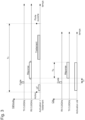
figure 2 représente différents signaux émis et reçus entre le dispositif d'accès et l'objet portable du système d'accès de lafigure 1 selon une première variante du procédé d'accès sécurisé selon l'invention, - la
figure 3 représente différents signaux émis et reçus entre le dispositif d'accès et l'objet portable du système d'accès de lafigure 1 selon une seconde variante du procédé d'accès sécurisé selon l'invention, - la
figure 4 représente différents signaux émis et reçus entre le dispositif d'accès et l'objet portable du système d'accès de lafigure 1 selon une troisième variante du procédé d'accès sécurisé selon l'invention, et - la
figure 5 représente différents signaux émis et reçus entre le dispositif d'accès et l'objet portable du système d'accès de lafigure 1 selon une quatrième variante du procédé d'accès sécurisé selon l'invention.
- there
figure 1 represents an embodiment of a secure access system to a determined space for the implementation of the access method according to the invention, - there
picture 2 represents different signals transmitted and received between the access device and the portable object of the access system of thefigure 1 according to a first variant of the secure access method according to the invention, - there
picture 3 represents different signals transmitted and received between the access device and the portable object of the access system of thefigure 1 according to a second variant of the secure access method according to the invention, - there
figure 4 represents different signals transmitted and received between the access device and the portable object of the access system of thefigure 1 according to a third variant of the secure access method according to the invention, and - there
figure 5 represents different signals transmitted and received between the access device and the portable object of the access system of thefigure 1 according to a fourth variant of the secure access method according to the invention.
Dans la description suivante, tous les composants du système d'accès sécurisé pour la mise en oeuvre du procédé d'accès sécurisé, qui sont bien connus d'un homme du métier dans ce domaine technique, ne sont décrits que de manière simplifiée.In the following description, all the components of the secure access system for implementing the secure access method, which are well known to a person skilled in the art in this technical field, are only described in a simplified manner.
La
Bien entendu, il peut s'agir d'un autre espacé déterminé, tel qu'un bus, une chambre d'un bâtiment sécurisé, un coffre-fort ou tout autre espace n'autorisant l'entrée qu'à des personnes autorisées avec leur objet portable personnalisé. De plus, l'objet portable 3 peut également être une carte ou un badge, une montre, une bague, un téléphone portable ou tout autre objet pouvant comprendre un circuit électronique capable d'établir une communication avec le dispositif d'accès ou de déverrouillage 2.Of course, it can be another specific space, such as a bus, a room in a secure building, a safe or any other space allowing entry only to authorized persons with their personalized portable object. In addition, the portable object 3 can also be a card or a badge, a watch, a ring, a mobile phone or any other object that can include an electronic circuit capable of establishing communication with the access or unlocking device. 2.
Selon le procédé d'accès sécurisé au véhicule par la clé électronique 3, il doit être détecté assez précisément la distance séparant la clé électronique personnalisée 3 du dispositif d'accès ou de déverrouillage 2. Dès l'activation de la clé électronique 3, une transmission et réception en décalage temporel ou en différé de signaux radiofréquences de commande ou de données, qui peuvent être codés, s'effectuent depuis le dispositif de déverrouillage 2 vers la clé électronique 3 et inversement. Une fusion de l'information de distance dans un signal réponse codé de la clé électronique 3 transmise au dispositif de déverrouillage 2 peut aussi être effectuée pour empêcher toute attaque par relais intermédiaires. Un traitement numérique des signaux est réalisé dans le dispositif de déverrouillage 2 de manière à reconnaître la clé électronique 3, ainsi qu'en partie dans la clé électronique 3, afin de permettre l'ouverture et la mise en marche du véhicule. Il est ainsi déterminé précisément dans le dispositif de déverrouillage 2, le temps de vol des signaux entre le dispositif et la clé et inversement, et de ce fait la distance séparant le dispositif d'accès et la clé électronique pour autoriser l'accès au véhicule.According to the method of secure access to the vehicle by the electronic key 3, the distance separating the personalized electronic key 3 from the access or unlocking device 2 must be detected fairly precisely. As soon as the electronic key 3 is activated, a transmission and reception in Time or delayed shifting of radio frequency control or data signals, which can be coded, takes place from the unlocking device 2 to the electronic key 3 and vice versa. A fusion of the distance information in a coded response signal from the electronic key 3 transmitted to the unlocking device 2 can also be performed to prevent any attack by intermediate relays. A digital processing of the signals is carried out in the unlocking device 2 so as to recognize the electronic key 3, as well as partly in the electronic key 3, in order to allow the opening and starting of the vehicle. It is thus precisely determined in the unlocking device 2, the time of flight of the signals between the device and the key and vice versa, and therefore the distance separating the access device and the electronic key to authorize access to the vehicle. .
Le dispositif d'accès ou de déverrouillage 2 du système d'accès 1 comprend notamment un transmetteur 21, un récepteur 22 et au moins une unité de traitement numérique des signaux 25, qui est reliée au transmetteur 21 et au récepteur 22. Dans cette forme d'exécution, une seule antenne 26 est reliée au transmetteur 21 et au récepteur 22 par l'intermédiaire d'un élément de commutation 120. L'élément de commutation 120 est un multiplexeur à deux entrées reliées respectivement au transmetteur 21 et au récepteur 22 et à une sortie reliée à l'antenne 26. Ce multiplexeur 120 est commandé par l'unité de traitement 25 pour permettre soit la transmission de signaux à haute fréquence par l'antenne 26 depuis le transmetteur 21, soit la réception de signaux à haute fréquence par l'antenne 26 vers le récepteur 22. Un oscillateur local 23, qui est de préférence un oscillateur à résonateur à quartz 24, est également prévu pour cadencer les opérations du dispositif de déverrouillage 2.The access or unlocking device 2 of the access system 1 notably comprises a
L'unité de traitement numérique 25 peut comprendre non représentés un microprocesseur cadencé par l'oscillateur local 23, une mémoire à plusieurs registres, un système de chiffrage symétrique ou asymétrique avec générateur de nombres aléatoires, ainsi qu'un système de gestion de clés de chiffrage. L'unité de traitement numérique 25 peut encore comprendre non représentés, un convertisseur analogique numérique ADC pour convertir les signaux intermédiaires en signaux numériques intermédiaires, un détecteur d'enveloppe des signaux numériques intermédiaires, un élément à retard, un générateur de modulation en fréquence de signaux. L'unité de traitement numérique 25 comprend encore un convertisseur numérique-analogique DAC pour convertir des signaux numériques à transmettre à la clé électronique 3.The
La clé électronique 3 du système d'accès 1 comprend notamment un transmetteur 31, un récepteur 32 et au moins une unité de traitement numérique 35, qui est reliée au transmetteur 31 et au récepteur 32. Dans cette forme d'exécution, une seule antenne 36 est reliée au transmetteur 31 et au récepteur 32 par l'intermédiaire d'un élément de commutation 150. L'élément de commutation 150 est un multiplexeur à deux entrées reliées respectivement au transmetteur 31 et au récepteur 32 et à une sortie reliée à l'antenne 36. Ce multiplexeur 150 est commandé par l'unité de traitement numérique 35 pour permettre soit la transmission de signaux à haute fréquence par l'antenne 36 depuis le transmetteur 31, soit la réception de signaux à haute fréquence par l'antenne 36 vers le récepteur 32 comme pour le dispositif d'accès ou de déverrouillage 2.The electronic key 3 of the access system 1 notably comprises a
Un oscillateur local 33, qui est de préférence un oscillateur à résonateur à quartz 34, est également prévu pour cadencer les opérations dans la clé électronique 3 et principalement le traitement par l'intermédiaire de l'unité de traitement numérique 35. Le signal d'oscillation de l'oscillateur local 33 peut être à une fréquence de l'ordre de 26 MHz ou à une fréquence divisée par un ensemble de diviseurs par deux. Cet oscillateur local 33 est similaire à l'oscillateur local 23 à résonateur à quartz 24 du dispositif de déverrouillage 2. Donc la fréquence du signal d'oscillation est sensiblement similaire à ± 40 ppm. Cela peut permettre d'avoir une bonne synchronisation de traitement dans le dispositif de déverrouillage 2 et dans la clé électronique 3 après une étape de calibration initiale ou durant le procédé d'accès sécurisé expliqué ci-dessous.A
L'unité de traitement numérique 35 peut comprendre non représenté un processeur ou une machine d'état cadencé par l'oscillateur local 33, une mémoire à plusieurs registres, un système de chiffrement symétrique ou asymétrique avec générateur de nombres aléatoires, ainsi qu'un système de gestion de clés de chiffrage. L'unité de traitement numérique 35 peut aussi comprendre, non représentés, un convertisseur analogique numérique ADC pour convertir les signaux intermédiaires en signaux numériques intermédiaires, un détecteur d'enveloppe des signaux numériques intermédiaires, un élément à retard, un générateur de modulation en fréquence de signaux. L'unité de traitement numérique 35 comprend encore un convertisseur numérique-analogique pour convertir des signaux numériques à transmettre au dispositif de déverrouillage 2.The
Suite à une commande d'activation provenant d'une poignée de porte du véhicule par exemple ou d'une commande transmise par la clé électronique 3, le transmetteur 21 du dispositif d'accès ou de déverrouillage 2 est capable de transmettre un signal de commande ou de données par l'antenne 26 à destination de l'antenne 36 de la clé électronique 3 expliquée en détail ci-après. Dans le cas d'une commande d'activation provenant du véhicule, le signal d'activation transmis par le dispositif est un signal à basse fréquence LF. Par contre, si la commande d'activation provient de la clé électronique 3, le dispositif d'accès ou de déverrouillage 2 à l'écoute va transmettre un signal de commande ou de données à haute fréquence. Cette haute fréquence dans cette forme d'exécution du système d'accès 1 peut être par exemple à une fréquence ISM à 5.8 GHz. Le récepteur 22 est capable de recevoir par l'antenne de réception 26 un signal radiofréquence à la même fréquence porteuse provenant de la clé électronique 3 interrogée.Following an activation command from a door handle of the vehicle, for example, or a command transmitted by the electronic key 3, the
Dans le dispositif d'accès ou de déverrouillage 2, le transmetteur 21 comprend un synthétiseur de fréquence 113, qui est utilisé aussi pour le récepteur 22. Le synthétiseur de fréquence 113 reçoit un signal de référence de l'oscillateur 23 à résonateur à quartz 24. Le synthétiseur de fréquence 113 est susceptible de fournir des signaux oscillants à haute fréquence à un premier mélangeur 114 et à un second mélangeur 115. Le premier mélangeur 114 reçoit depuis l'unité de traitement numérique 25 au moins un signal intermédiaire en phase IF_I, qui est filtré dans un filtre passe-bas 116 pour convertir en fréquence vers le haut ce signal intermédiaire par un premier signal oscillant du synthétiseur de fréquence 113. Le second mélangeur 115 reçoit depuis l'unité de traitement numérique 25 au moins un signal intermédiaire en quadrature IF_Q, qui est filtré dans un filtre passe-bas 117 pour convertir en fréquence vers le haut ce signal intermédiaire par un second signal oscillant du synthétiseur de fréquence 113. Le signal de sortie du premier mélangeur 114 et le signal de sortie du second mélangeur 115 sont additionnés dans un additionneur 112 du transmetteur 21. Un amplificateur de sortie 111 est relié en sortie de l'additionneur 112 pour amplifier le signal radiofréquence de sortie à transmettre par la première antenne 26 par l'intermédiaire du multiplexeur 120 en mode de transmission.In the access or unlocking device 2, the
Il est à noter que le premier signal oscillant fourni par le synthétiseur de fréquence 113 du transmetteur 21 est un signal oscillant en phase, alors que le second signal oscillant est un signal oscillant en quadrature. Ceci est prévu pour un mélange respectif avec le signal intermédiaire filtré en phase IF_I et le signal intermédiaire filtré en quadrature IF_Q. Le synthétiseur de fréquence 113 est donc prévu pour générer des signaux oscillants en phase et en quadrature à une fréquence voisine de 5.8 GHz pour les deux mélangeurs 114, 115.It should be noted that the first oscillating signal supplied by the
Chaque signal intermédiaire IF_I et IF_Q, comme expliqué ci-après en référence notamment aux
Dans le dispositif d'accès ou de déverrouillage 2, le récepteur 22 comprend un amplificateur à faible bruit d'entrée 121 pour recevoir un signal radiofréquence de l'antenne 26 par l'intermédiaire du multiplexeur 120 en mode de réception. L'amplificateur à faible bruit d'entrée 121 du récepteur 22 permet d'amplifier et filtrer le signal radiofréquence reçu. Un premier mélangeur 123 du récepteur 22 est prévu pour convertir en fréquence le signal radiofréquence amplifié et filtré par un signal oscillant en phase LO_I provenant du synthétiseur de fréquence 113, afin de fournir un signal intermédiaire en phase IF_I. Ce signal intermédiaire en phase IF_I est filtré par un filtre passe-bas 125. Un second mélangeur 124 du récepteur 22 est prévu pour convertir en fréquence le signal radiofréquence amplifié et filtré par un signal oscillant en quadrature LO_Q du synthétiseur de fréquence 113, afin de fournir un signal intermédiaire en quadrature IF_Q. Le signal intermédiaire en quadrature IF_Q est filtré par un autre filtre passe-bas 126. Les signaux intermédiaires en phase IF_I et en quadrature IF_Q filtrés sont transmis à l'unité de traitement numérique 25.In the access or unlocking device 2, the
Dans l'unité de traitement numérique 25, il y a tout d'abord un convertisseur analogique numérique ADC non représenté pour convertir les signaux intermédiaires en signaux numériques intermédiaires à traiter dans l'unité de traitement 25. L'unité de traitement 25 peut comprendre encore, non représentés, un détecteur d'enveloppe des signaux numériques intermédiaires, au moins une unité de mémorisation, telle qu'une mémoire non volatile ayant plusieurs registres, et un convertisseur numérique-analogique pour convertir des signaux numériques à transmettre. L'unité de traitement 25 est cadencée par un signal de cadencement fourni par l'oscillateur local 23, qui peut être à une fréquence de l'ordre de 26 MHz ou à une fréquence divisée par un ensemble de diviseurs par deux.In the
Dans la clé électronique 3, il n'y a également qu'un synthétiseur de fréquence 143 pour générer des signaux oscillants en phase et en quadrature à une fréquence voisine de 5.8 GHz. Dans le transmetteur 31 de la clé électronique 3, le synthétiseur de fréquence 143 fournit un signal oscillant en phase à un premier mélangeur 145 pour élever en fréquence le signal intermédiaire en phase IF_I à transmettre et qui est filtré dans un filtre passe-bas 147 en venant de l'unité de traitement numérique 35. Le synthétiseur de fréquence 143 fournit un signal oscillant en quadrature à un second mélangeur 146 pour élever en fréquence le signal intermédiaire en quadrature IF_Q à transmettre et qui est filtré dans un filtre passe-bas 148 en venant de l'unité de traitement numérique 35. Les signaux de sortie des deux mélangeurs sont additionnés dans un additionneur 142 avant d'être amplifiés par un amplificateur 141, dont la sortie est connectée à un élément de commutation 150 relié à l'unique antenne 36 de transmission et de réception de signaux. En fonction d'une commutation de transmission commandée à l'élément de commutation 150 notamment par l'unité de traitement numérique 35, il y a une transmission d'un signal fourni par le transmetteur 31 par l'antenne 36 dans le mode de transmission. Cet élément de commutation 150 est de préférence un multiplexeur à deux entrées et une sortie liée à l'antenne 36 avec une commande de commutation provenant de l'unité de traitement numérique 35 cadencée par un signal de cadencement provenant de l'oscillateur local 33. Une entrée du multiplexeur est reliée au transmetteur 31, alors qu'une autre entrée est reliée au récepteur 32.In the electronic key 3, there is also only one
Le récepteur 32 comprend un amplificateur à faible bruit 131 relié à une entrée du multiplexeur 150 en mode de réception. Le signal de sortie de l'amplificateur 131 est fourni à un premier mélangeur 133 et à un second mélangeur 134. Le synthétiseur de fréquence 143 fournit également un signal oscillant en phase LO_I pour le premier mélangeur 133 du récepteur 32 et un signal oscillant en quadrature LO_Q pour le second mélangeur 134 du récepteur 32. Un premier signal intermédiaire en phase IF_I est fourni en sortie du premier mélangeur 133 à une fréquence abaissée, et un second signal intermédiaire en quadrature IF_Q est fourni en sortie du second mélangeur 134 à une fréquence abaissée. Le signal intermédiaire en phase IF_I est filtré dans un filtre passe-bas 135 et transmis à l'unité de traitement numérique 35. Le signal intermédiaire en quadrature IF_Q est filtré dans un filtre passe-bas 136 et transmis à l'unité de traitement numérique 35.
Dans une phase initiale suite à la commande d'activation effectuée sur un élément du véhicule, il peut tout d'abord être transmis par la première antenne 26 du transmetteur 21, un signal d'activation à basse fréquence LF pour réveiller la clé électronique 3 à proximité du véhicule. Cependant, il peut aussi être envisagé d'activer ladite clé électronique 3 par un bouton poussoir qu'elle comprend ou par un autre organe de contrôle de ladite clé, comme une touche tactile. A la réception du signal d'activation de la clé électronique 3, le dispositif d'accès ou de déverrouillage 2 peut transmettre par exemple un signal d'interrogation à haute fréquence à la clé électronique 3. Les différentes étapes du procédé, qui suit cette phase initiale, sont expliquées plus en détail par la suite.In an initial phase following the activation command carried out on an element of the vehicle, it can first of all be transmitted by the
Il est à noter qu'il peut être prévu dans le dispositif de déverrouillage 2, un générateur pseudo-aléatoire de bruit comme décrit dans le brevet
Selon une première variante du procédé d'accès sécurisé selon la
La clé électronique reçoit ce premier signal de base et le démodule en définissant le temps. Ensuite, la clé électronique génère un second signal codé, tel qu'un signal codé de réponse après un premier temps défini de transmission TF bien déterminé depuis l'initiation du signal de base dans le dispositif de déverrouillage. Ce premier temps TF défini de transmission, qui peut être de l'ordre de 0.1 ms, est obtenu par la temporisation suite à la réception du signal de base et grâce à un oscillateur local similaire à celui du dispositif de déverrouillage. Ce signal codé de réponse est reçu par le dispositif de déverrouillage. Un traitement est effectué en décalage temporel, c'est-à-dire après un laps de temps dans le dispositif de déverrouillage pour déterminer les temps de vol entre les deux entités et le premier temps défini de réponse de la clé électronique. Comme la temporisation est très précise dans le dispositif et dans la clé et que le signal de base et le signal codé de réponse sont transmis à haut débit par exemple à 26 Mbits/s, il est facile de déterminer la distance réelle séparant la clé électronique du véhicule. De plus, cela permet de garantir une très grande sécurité pour empêcher l'ouverture du véhicule par l'intermédiaire de relais intermédiaires de personnes mal intentionnées.The electronic key receives this first basic signal and demodulates it by defining the time. Then, the electronic key generates a second coded signal, such as a coded response signal after a first defined transmission time T F well determined since the initiation of the basic signal in the unlocking device. This first defined transmission time T F , which can be of the order of 0.1 ms, is obtained by the time delay following reception of the base signal and thanks to a local oscillator similar to that of the unlocking device. This coded response signal is received by the unlocking device. A processing is carried out in time shift, that is to say after a period of time in the unlocking device to determine the flight times between the two entities and the first defined response time of the electronic key. As the timing is very precise in the device and in the key and as the basic signal and the coded response signal are transmitted at high speed, for example at 26 Mbits/s, it is easy to determine the actual distance separating the electronic key of the vehicle. In addition, this makes it possible to guarantee very high security in order to prevent the opening of the vehicle by means of intermediate relays by malicious persons.
Au terme de la transmission du signal codé de réponse de la clé électronique 3, la clé électronique 3 peut être automatiquement désactivée et rester dans un mode de repos. Le contrôle de la temporisation et du code réponse de la clé électronique 3 peut se faire dans l'unité de traitement 25 à processeur du dispositif d'accès ou de déverrouillage 2 en différé après la désactivation de la clé électronique. Une commande d'ouverture de la porte du véhicule peut être commandée par la suite. Le temps T0 entre l'activation de la clé électronique 3 et l'ouverture de la porte du véhicule peut être de l'ordre de 1 ms.At the end of the transmission of the coded response signal from the electronic key 3, the electronic key 3 can be automatically deactivated and remain in a rest mode. The control of the time delay and of the response code of the electronic key 3 can be done in the
Selon une seconde variante du procédé d'accès sécurisé selon la
La clé électronique reçoit ce signal de base codé et le démodule en définissant le temps. Ensuite, la clé électronique génère un signal codé de réponse après un premier temps défini de transmission TF bien déterminé depuis l'initiation du signal de base Code dans le dispositif de déverrouillage. Ce premier temps TF défini de transmission, qui peut être de l'ordre de 0.1 ms, est obtenu par la temporisation suite à la réception du signal de base et grâce à un oscillateur local similaire à celui du dispositif de déverrouillage.The electronic key receives this coded base signal and demodulates it by setting the time. Then, the electronic key generates a coded response signal after a first well-determined defined transmission time T F since the initiation of the basic Code signal in the unlocking device. This first defined transmission time T F , which can be of the order of 0.1 ms, is obtained by the time delay following reception of the base signal and thanks to a local oscillator similar to that of the unlocking device.
Ce signal codé de réponse est un signal codé brouillé ("scrambled" en terminologie anglaise) avec une modulation supplémentaire sur le signal de base codé reçu ou un signal chiffré avec une clé de chiffrage symétrique ou asymétrique programmée ou générée auparavant. La génération de ce signal codé de réponse brouillé est plus longue que celui de la première variante du procédé d'accès. La modulation peut être à 1 Mbits/s dans le signal codé de réponse qui est à une fréquence par exemple de 5.8 GHz. La durée TB de ce signal codé de réponse brouillé peut être de l'ordre de 0.25 ms.This coded response signal is a scrambled coded signal (“scrambled” in English terminology) with an additional modulation on the coded basic signal received or a signal encrypted with a symmetrical or asymmetrical encryption key programmed or generated beforehand. The generation of this scrambled response coded signal takes longer than that of the first variant of the access method. The modulation can be at 1 Mbits/s in the coded response signal which is at a frequency of for example 5.8 GHz. The duration T B of this scrambled response coded signal may be of the order of 0.25 ms.
Ce signal codé de réponse brouillé est reçu par le dispositif de déverrouillage dans une fenêtre temporelle de réception déterminée dans le dispositif de déverrouillage. Le dispositif est agencé pour recevoir dans cette fenêtre temporelle ou intervalle temporel, le signal codé de réponse brouillé. La durée de cette fenêtre temporelle de réception est équivalente à celle TB du signal codé de réponse brouillé.This scrambled response coded signal is received by the unlocking device in a reception time window determined in the unlocking device. The device is arranged to receive, in this time window or time interval, the scrambled response coded signal. The duration of this reception time window is equivalent to that T B of the scrambled response coded signal.
Après la réception complète du signal codé de réponse brouillé, un traitement est effectué dans l'unité de traitement du dispositif de déverrouillage. Dans l'unité de traitement, le signal codé de réponse reçu de la clé électronique est comparé avec la version générée localement sur la base du code initial. Après cela, il y a une détermination des temps de vol entre les deux entités, ainsi que le premier temps TF défini de réponse de la clé électronique. Comme la temporisation est très précise dans le dispositif et dans la clé et que le signal de base et le signal codé de réponse sont transmis à haut débit par exemple à 26 Mbits/s, il est facile de déterminer la distance réelle séparant la clé électronique du véhicule. Cela garantit également l'accès au véhicule uniquement à la clé électronique à proximité dudit véhicule pour une grande sécurité.After complete reception of the scrambled response coded signal, processing is performed in the processing unit of the unlocking device. In the processing unit, the coded response signal received from the electronic key is compared with the version generated locally on the basis of the initial code. After that, there is a determination of the flight times between the two entities, as well as the first defined response time T F of the electronic key. As the timing is very precise in the device and in the key and as the basic signal and the response coded signal are transmitted at high speed, for example at 26 Mbits/s, it is easy to determine the actual distance separating the electronic key of the vehicle. This also guarantees access to the vehicle only to the electronic key near said vehicle for greater security.
Comme pour la première variante du procédé au terme de la transmission du signal codé de réponse brouillé de la clé électronique, la clé électronique peut être automatiquement désactivée pour rester dans un mode de repos. Une commande d'ouverture de la porte du véhicule peut être commandée par la suite après le traitement dans l'unité de traitement. Le temps T0 entre l'activation de la clé électronique et l'ouverture de la porte du véhicule peut être de l'ordre de 10 ms.As for the first variant of the method, at the end of the transmission of the scrambled response coded signal from the electronic key, the electronic key can be automatically deactivated to remain in a rest mode. A command to open the door of the vehicle can be subsequently commanded after the processing in the processing unit. The time T 0 between the activation of the electronic key and the opening of the door of the vehicle can be of the order of 10 ms.
Dans les variantes du procédé d'accès sécurisé décrites en référence aux
Selon une troisième variante du procédé d'accès sécurisé selon la
Le dispositif de déverrouillage transmet ensuite un signal de base Code, qui est un signal à code de brassage à moyen débit de l'ordre de 1 Mbits/s ou un signal à code de brassage ou aléatoire chiffré avec une clé symétrique ou asymétrique. Cette transmission du signal de base est plus longue que la transmission du signal de base des première et seconde variantes du procédé, par exemple de l'ordre de 1 ms. Avec un moyen débit de transmission, la détermination de distance est effectuée par la suite avec une précision moindre, mais avec une complexité des composants de traitement réduite.The unlocking device then transmits a basic Code signal, which is a medium bit rate shuffling code signal of the order of 1 Mbits/s or a shuffling or random code signal encrypted with a symmetric or asymmetric key. This transmission of the basic signal is longer than the transmission of the basic signal of the first and second variants of the method, for example of the order of 1 ms. With a medium transmission rate, the distance determination is performed subsequently with less accuracy, but with reduced complexity of the processing components.
La clé électronique reçoit ce signal de base codé, le démodule et le déchiffre afin de paramétrer l'analyse effectuée dans l'unité de traitement de la clé électronique. Comme les deux oscillateurs du dispositif et de la clé ne sont pas encore calibrés, la synchronisation à la réception du signal de base codé par la clé électronique est encore une synchronisation floue. Dès la réception du signal CW (envoyé par la clé), un calcul d'erreur de fréquence des oscillateurs est effectué dans l'unité de traitement du dispositif de déverrouillage.The electronic key receives this coded basic signal, demodulates it and deciphers it in order to configure the analysis carried out in the processing unit of the electronic key. As the two oscillators of the device and of the key are not yet calibrated, the synchronization on reception of the basic signal coded by the electronic key is still a fuzzy synchronization. As soon as the CW signal is received (sent by the key), an oscillator frequency error calculation is performed in the processing unit of the unlocking device.
Après correction de fréquence de l'oscillateur local du dispositif par exemple, une nouvelle transmission d'un premier signal codé de réponse Réponse 1 est effectuée du dispositif de déverrouillage en différé, c'est-à-dire après un temps déterminé TR1 suite à la transmission du signal de base à code de brassage. Le premier signal codé de réponse est transmis vers la clé électronique, cette transmission véhiculant une synchronisation précise. La clé électronique reçoit ce premier signal réponse brouillé du dispositif de déverrouillage par exemple dans une fenêtre temporelle de réception équivalente à la durée du premier signal codé de réponse.After frequency correction of the local oscillator of the device, for example, a new transmission of a first coded response signal Response 1 is carried out from the unlocking device on a deferred basis, that is to say after a determined time T R1 following transmission of the shuffling code base signal. The first response coded signal is transmitted to the electronic key, this transmission conveying precise synchronization. The electronic key receives this first scrambled response signal from the unlocking device, for example in a reception time window equivalent to the duration of the first coded response signal.
Suite à la réception de ce premier signal codé de réponse brouillé, un traitement du premier signal réponse brouillé est effectué dans l'unité de traitement de la clé électronique. Un calcul d'un temps de départ par une corrélation du premier signal réponse brouillé attendu (décrypté depuis le code de brassage initial) est effectué. Cette corrélation permet d'aligner précisément le début de l'émission du second signal de réponse par rapport à l'arrivée de la première réponse. Par la suite, la clé électronique génère un second signal codé de réponse brouillé (pseudo aléatoire), qui est transmis au terme du traitement dans l'unité de traitement. La transmission de ce second signal codé de réponse est effectuée avec une bonne synchronisation et un haut débit de par exemple 125 Mbits/s vers le dispositif de déverrouillage.Following receipt of this first coded scrambled response signal, processing of the first scrambled response signal is carried out in the electronic key processing unit. A calculation of a start time by a correlation of the expected first scrambled response signal (decrypted from the initial shuffling code) is carried out. This correlation makes it possible to precisely align the start of the transmission of the second response signal with respect to the arrival of the first response. Subsequently, the electronic key generates a second coded scrambled response signal (pseudo-random), which is transmitted at the end of the processing in the processing unit. The transmission of this second coded response signal is carried out with good synchronization and a high bit rate of for example 125 Mbits/s to the unlocking device.
Le dispositif de déverrouillage reçoit ce second signal codé de réponse Réponse 2, qui est brouillé (pseudo aléatoire), dans une fenêtre temporelle de réception bien synchronisée par le dispositif de déverrouillage. Par la suite une corrélation du second signal codé de réponse de la clé électronique est effectuée dans l'unité de traitement du dispositif en différé, c'est-à-dire après un temps déterminé au terme de la réception du second signal codé de réponse brouillé (pseudo aléatoire). Cette corrélation du second signal codé de réponse brouillé est effectuée en fonction d'un codage attendu de la réponse de la clé électronique. Un calcul des temps de vol des signaux entre le dispositif et la clé et entre la clé et le dispositif est encore effectué dans l'unité de traitement. Une distance entre la clé électronique et le dispositif de déverrouillage peut encore être déterminée, afin de permettre l'ouverture du véhicule, si la clé est bien reconnue et qu'elle se trouve à une distance bien déterminé à proximité du véhicule par rapport à un seuil de distance déterminé.The unlocking device receives this second coded response signal Response 2, which is scrambled (pseudo-random), in a reception time window well synchronized by the unlocking device. Subsequently, a correlation of the second coded response signal from the electronic key is carried out in the processing unit of the device offline, that is to say after a determined time at the end of the reception of the second coded response signal scrambled (pseudo random). This correlation of the scrambled second coded response signal is performed according to an expected coding of the response from the electronic key. A calculation of the times of flight of the signals between the device and the key and between the key and the device is still performed in the processing unit. A distance between the electronic key and the unlocking device can still be determined, in order to allow the opening of the vehicle, if the key is well recognized and that it is at a well determined distance near the vehicle with respect to a determined distance threshold.
Avec cette troisième variante du procédé d'accès sécurisé décrit ci-dessus, cela garantit une grande sécurité. Cela permet de déterminer tout relais intermédiaire (donc délai supplémentaire de transmission) utilisé pour tenter d'ouvrir le véhicule à l'insu du titulaire de la clé électronique. Après reconnaissance de la clé électronique, le véhicule peut être ouvert un laps de temps après le traitement dans l'unité de traitement du dispositif. La durée totale T0 depuis l'activation de la clé électronique jusqu'au traitement complet de l'information stockée dans le dispositif de déverrouillage peut être de l'ordre de 10 ms.With this third variant of the secure access method described above, this guarantees high security. This makes it possible to determine any intermediate relay (therefore additional transmission delay) used to attempt to open the vehicle without the knowledge of the holder of the electronic key. After recognition of the electronic key, the vehicle can be opened a period of time after processing in the processing unit of the device. The total duration T 0 from the activation of the electronic key until the complete processing of the information stored in the unlocking device can be of the order of 10 ms.
Selon une quatrième variante du procédé d'accès sécurisé selon la
La clé électronique reçoit ce signal de base codé, le démodule et le déchiffre. Comme le débit et donc la largeur de bande sont réduits lors de cette première transmission, la synchronisation à la réception du signal de base codé par la clé électronique est encore une synchronisation floue. La clé électronique effectue, dans son unité de traitement, un calcul d'erreur de fréquence du dispositif de déverrouillage à la clé électronique sur la base du signal de base à code de brassage reçu. Après ce traitement, une correction de fréquence de l'oscillateur local de la clé intervient.The electronic key receives this coded basic signal, demodulates it and decrypts it. As the bit rate and therefore the bandwidth are reduced during this first transmission, the synchronization on reception of the basic signal coded by the electronic key is still a fuzzy synchronization. The electronic key performs, in its processing unit, a frequency error calculation from the unlocking device to the electronic key on the basis of the basic shuffling code signal received. After this processing, a frequency correction of the local oscillator of the key takes place.
Une transmission d'un premier signal codé de réponse Réponse 1 est effectuée du dispositif de déverrouillage en différé, c'est-à-dire après un temps TR1 déterminé suite à la transmission du signal de base à code de brassage. Ce premier signal codé de réponse est un signal à code pseudo-aléatoire de bruit PN, qui est à très haut débit par exemple de l'ordre de 125 Mbits/s. Le premier signal codé de réponse est transmis vers la clé électronique pour avoir, après corrélation dans la clé électronique, une synchronisation précise. Une mémorisation de ce signal à code PN reçu est effectuée dans un registre d'une mémoire de la clé électronique. La clé électronique reçoit ce premier signal réponse PN du dispositif de déverrouillage dans une fenêtre temporelle de réception bien définie.A transmission of a first coded response signal Response 1 is carried out from the unlocking device on a deferred basis, that is to say after a determined time T R1 following the transmission of the basic shuffling code signal. This first coded response signal is a pseudo-random noise code signal PN, which has a very high bit rate, for example of the order of 125 Mbits/s. The first coded response signal is transmitted to the electronic key to have, after correlation in the electronic key, a precise synchronization. This received PN code signal is stored in a register of a memory of the electronic key. The electronic key receives this first response signal PN from the unlocking device in a well-defined reception time window.
A la réception de ce premier signal réponse PN, une corrélation de la première réponse du dispositif de déverrouillage avec la séquence PN déduite du code de brassage initial est effectuée dans l'unité de traitement de la clé. Cette corrélation permet de définir précisément le temps d'envoi d'un second signal à code pseudo-aléatoire de bruit PN (qui est à très haut débit par exemple de l'ordre de 125 Mbits/s), après un temps déterminé depuis la transmission du premier signal codé de réponse du dispositif à la transmission de la clé électronique. Ce temps déterminé tient compte en plus du temps fixé des temps de vol des signaux entre le dispositif et la clé et entre la clé et le dispositif. Une synchronisation précise est obtenue au moment de la transmission du second signal réponse à code pseudo-aléatoire de bruit PN, qui est à très haut débit par exemple de l'ordre de 125 Mbits/s.Upon receipt of this first PN response signal, a correlation of the first response from the unlocking device with the PN sequence deduced from the initial shuffling code is carried out in the key processing unit. This correlation makes it possible to precisely define the sending time of a second pseudo-random PN noise code signal (which is at very high speed, for example of the order of 125 Mbits/s), after a time determined from the transmission of the first coded response signal from the device to the transmission of the electronic key. This determined time also takes into account the fixed time of the flight times of the signals between the device and the key and between the key and the device. Precise synchronization is obtained at the time of transmission of the second pseudo-random noise code response signal PN, which is at a very high bit rate, for example of the order of 125 Mbits/s.
Le dispositif de déverrouillage reçoit ce second signal réponse à code pseudo-aléatoire de bruit PN dans une fenêtre temporelle de réception bien synchronisée et mémorise dans un premier registre d'une mémoire l'information de la seconde réponse de la clé électronique. La durée de réception dans la fenêtre de réception du dispositif est équivalente à la durée du second signal réponse de la clé électronique. Dans l'unité de traitement du dispositif à la suite de la réception du second signal réponse de la clé, il est effectué une corrélation avec le code PN connu de la seconde réponse Réponse 2 de la clé électronique. Un calcul sûr des temps de vol est encore déterminé de manière à déterminer également la distance séparant la clé électronique du dispositif de déverrouillage pour permettre d'ouvrir le véhicule un laps de temps après si la clé électronique est reconnue. Le temps T0 entre l'activation de la clé et l'ouverture de la porte du véhicule peut être de l'ordre de 10 ms.The unlocking device receives this second response signal with pseudo-random noise code PN in a well-synchronized reception time window and stores in a first register of a memory the information of the second response from the electronic key. The receive time within the device receive window is equivalent to the duration of the second response signal from the electronic key. In the processing unit of the device following receipt of the second response signal from the key, a correlation is made with the known PN code of the second response Response 2 from the electronic key. A reliable calculation of flight times is further determined so as to also determine the distance separating the electronic key from the unlocking device to enable the vehicle to be opened a lapse of time later if the electronic key is recognized. The time T 0 between the activation of the key and the opening of the door of the vehicle can be of the order of 10 ms.
Il est à noter que la durée de la deuxième réponse, qui est transmise depuis la clé à destination du véhicule, peut être plus longue que la première réponse, qui est transmise du véhicule vers la clé. De ce fait, cela permet d'avoir une augmentation du gain de corrélation, et avantageusement de réduire la puissance d'émission de la clé en conservant un rapport signal sur bruit similaire à celui de la transmission voiture clé, où il est plus aisé d'obtenir de la puissance.It should be noted that the duration of the second response, which is transmitted from the key to the vehicle, may be longer than the first response, which is transmitted from the vehicle to the key. As a result, this makes it possible to have an increase in the correlation gain, and advantageously to reduce the transmission power of the key while maintaining a signal-to-noise ratio similar to that of the car key transmission, where it is easier to to get power.
Il est encore à noter que toutes les étapes des différentes variantes du procédé d'accès sécurisé décrites ci-dessus peuvent être répétées successivement pour permettre l'ouverture du véhicule uniquement à la clé électronique personnalisée audit véhicule.It should also be noted that all the steps of the different variants of the secure access method described above can be repeated successively to allow the opening of the vehicle only with the personalized electronic key of said vehicle.
A partir de la description qui vient d'être faite, plusieurs variantes du procédé et système d'accès sécurisé à un espace déterminé peuvent être conçues par l'homme du métier sans sortir du cadre de l'invention définie par les revendications. Il peut être prévu dans le dispositif d'accès ou de déverrouillage et dans la clé électronique une antenne pour la transmission à une première haute fréquence et une antenne pour la réception à une seconde haute fréquence des signaux de communication. Il est à noter que pour chaque variante du système d'accès sécurisé, plusieurs antennes commutées sont également imaginables. Cela permet ainsi, au cours de plusieurs phases successives d'opération du système sur différentes antennes, l'utilisation d'une topologie à diversité d'antennes bien connue de l'homme de métier.From the description that has just been given, several variants of the method and system for secure access to a determined space can be designed by those skilled in the art without departing from the scope of the invention defined by the claims. There may be provided in the access or unlocking device and in the electronic key an antenna for the transmission at a first high frequency and an antenna for the reception at a second high frequency of the communication signals. It should be noted that for each variant of the secure access system, several switched antennas are also conceivable. This allows, during several successive phases of operation of the system on different antennas, the use of an antenna diversity topology well known to those skilled in the art.
Claims (19)
- Process for secure access to a determined space equipped with an access or unlocking device (2) by means of a customised wearable object (3) through a wireless signal communication, wherein the access or unlocking device (2) comprises a transmitter (21) of radiofrequency signals at high frequency, a receiver (22) of radiofrequency signals at high frequency, a processing unit (25) and a local oscillator (23) for clocking the operations of the access or unlocking device (2), and the wearable object (3) comprises a transmitter (31) of radiofrequency signals at high frequency, a receiver (32) of radiofrequency signals at high frequency, a processing unit (35) and a local oscillator (33) for clocking the operations of the wearable object (3),
wherein the process is characterised in that it comprises the steps of:- activating the wearable object (3),- transmitting a first coded signal from the access or unlocking device (2),- receiving the first coded signal from the access or unlocking device (2) in the wearable object (3) to demodulate the code by defining time and preparing a coded response signal, in order to transmit this coded response signal with synchronisation to the access or unlocking device (2) after a defined time of transmission (TF) following initiation and as of the transmission of the first coded signal in the access or unlocking device (2) and obtained by time counting following reception of the first coded signal and thanks to the local oscillator in the wearable object similar to that one of the device,- receiving the coded response signal from the wearable object (3) in the access or unlocking device (2),- processing the converted coded response signal in the processing unit (25) of the access or unlocking device (2), by checking the defined time delay and the response code of the wearable object (3), in order to determine the flight times of the signals between the access or unlocking device (2) and the wearable object (3) and deducing therefrom the distance separating the wearable object (3) and the access or unlocking device (2), to authorise access to the determined space, if the calculated distance is below a determined threshold after recognition of the wearable object (3). - Secure access process according to claim 1, characterised in that the wearable object (3) is deactivated at the end of the transmission of the coded response signal or just before the processing of the converted coded response signal in the processing unit (25) of the access or unlocking device (2).
- Secure access process according to claim 1, characterised in that the local oscillator (23) of the access or unlocking device (2) generates an oscillation signal at a frequency similar to the oscillation signal generated by the local oscillator (33) of the wearable object (3).
- Secure access process according to claim 1, characterised in that a time delay is started into the access or unlocking device (2) on transmission of the first coded signal to allow reception of the coded response signal of the wearable object (3) to be checked and to allow the flight times of the signals and the distance separating the access or unlocking device (2) and the wearable object (3) to be determined precisely, and in that the defined time of transmission (TF) is determined from the transmission of the first coded signal.
- Secure access process according to claim 1, characterised in that the processing in the processing unit (25) of the access or unlocking device (2) is conducted with time delay after reception of the coded response signal from the wearable object (3).
- Secure access process according to claim 1, characterised in that the access or unlocking device (2) transmits the first coded signal, which is a rolling code signal or a pseudo-random noise coded signal and which can be encrypted with a symmetric or asymmetric key, with a determined time interval after activation of the wearable object (3), wherein said first rolling code or pseudo-random noise coded signal received and decrypted by the wearable object (3) enables preparation of the coded response signal to be transmitted after the first defined time of transmission (TF).
- Secure access process according to claim 1, characterised in that the access or unlocking device (2) receives the coded response signal from the wearable object (3) in a reception window adjusted to the duration (TB) of the coded response signal and synchronised with the transmission of the coded response signal from the wearable object (3).
- Secure access process according to one of claims 1 and 7, characterised in that the access or unlocking device (2) transmits the first coded signal, which is a rolling code signal or a pseudo-random noise coded signal, which can be encrypted with a symmetric or asymmetric key, and in that the wearable object transmits a scrambled coded response signal with an additional modulation of data.
- Secure access process according to claim 8, characterised in that the frequency of the first coded signal transmitted through an antenna (26) of the access or unlocking device (2) and the frequency of the scrambled coded response signal transmitted through an antenna (36) of the wearable object (3) are identical in value in the range of 5.8 GHz, in that the first coded signal is at a high transmission rate in the range of 26 Mbits/s or 125 Mbits/s, and in that the additional modulation in the scrambled coded response signal is at a lower transmission rate in the range of 1 Mbits/s.
- Secure access process according to claim 1, characterised in that the frequency of the first coded signal transmitted through an antenna (26) of the access or unlocking device (2) is at a frequency in the range of 5.8 GHz and equal to the frequency of the coded response signal transmitted through an antenna (36) of the wearable object (3), and in that the first coded signal is at a high transmission rate in the range of 26 Mbits/s or 125 Mbits/s.
- Secure access process according to claim 1, wherein the local oscillator (23) of the access or unlocking device (2) is a quartz crystal (24) oscillator, and wherein the local oscillator (33) of the wearable object (3) is a quartz crystal (34) oscillator similar to the quartz crystal (24) of the access or unlocking device (2), characterised in that the first coded signal is transmitted by the access or unlocking device (2) and received by the wearable object (3), which conducts a parameterisation for an analysis in the processing unit (35) of the wearable object (3), in that after the transmission of the first coded signal, a coded response signal of the device (Response 1) scrambled by an additional modulation, is generated and transmitted by the access or unlocking device (2) with time delay (TR1), in that the wearable object receives the scrambled coded response signal from the device in a first time window for reception adjusted to the duration of the scrambled coded response signal of the device, in that a processing of the scrambled coded response signal of the device is conducted after conversion in the processing unit (35) of the wearable object (3) with time delay for the generation and transmission of the coded response signal from the wearable object (Response 2) scrambled by an additional modulation, in that the access or unlocking device (2) receives the scrambled coded response signal from the wearable object (3) in a second time window for reception of the device adjusted to the duration of the scrambled coded response signal from the wearable object (3), and in that a processing of the converted scrambled coded response signal of the wearable object (3) is conducted with time delay in the processing unit (25) of the access or unlocking device (2) for calculation of the flight times and the distance between the access or unlocking device (2) and the wearable object (3).
- Secure access process according to claim 11, characterised in that once activated, the wearable object (3) transmits a continuous carrier frequency signal (CW), which is received by the access or unlocking device (2) before transmission of the first coded signal, in that a calculation of frequency error of the local oscillator (33) of the wearable object (3) in relation to the local oscillator (23) of the access or unlocking device (2) is conducted in the processing unit (25) of the access or unlocking device (2), in that in parallel with the frequency error calculation, the first coded signal is transmitted by the access or unlocking device (2), and in that the scrambled coded response signal of the device is transmitted with a precise synchronisation request.
- Secure access process according to claim 11, characterised in that the frequency of the signals transmitted and received by the access or unlocking device (2) and the wearable object (3) are at a frequency in the range of 5.8 GHz, in that the data transfer rate of the first coded signal, which is a rolling code signal or a pseudo-random noise coded signal transmitted by the access or unlocking device (2), is of 1 Mbits/s, and in that the scrambled coded response signals, which are defined by pseudo-random noise coded signals, are at a transfer rate in the range of 26 Mbits/s or 125 Mbits/s with an additional modulation of 1 Mbits/s.
- Secure access process according to claim 11, characterised in that the first coded signal, which is a rolling code signal of the access or unlocking device (2), is received by the wearable object (3) and a calculation of frequency error of the local oscillator (23) of the access or unlocking device (2) in relation to the local oscillator (33) of the wearable object (3) is conducted in the processing unit (35) of the wearable object (3), in that the processing unit (35) of the wearable object (3) calculates a transmission time of the scrambled coded response signal of the wearable object (3) from the transmission of the scrambled coded response signal of the access or unlocking device (2) to define a precise synchronisation during the transmission of the scrambled coded response signal of the wearable object (3) received in the second reception window of the device.
- System (1) for secure access to a determined space for implementing the access process according to one of the preceding claims, in which the system (1) comprises an access or unlocking device (2), a customised wearable object (3) for a wireless signal communication with the access or unlocking device (2), wherein the access or unlocking device (2) comprises a transmitter (21) of radiofrequency signals at high frequency, a receiver (22) of radiofrequency signals at high frequency, a processing unit (25) and a local oscillator (23) for clocking the operations of the access or unlocking device (2), and the wearable object (3) comprises a transmitter (31) of radiofrequency signals at high frequency, a receiver (32) of radiofrequency signals at high frequency, a processing unit (35) and a local oscillator (33) for clocking the operations of the wearable object (3), the wearable object (3) being arranged after activation to receive a first coded signal from the access or unlocking device (2) to demodulate the code by defining time and preparing a coded response signal, in order to transmit this coded response signal with synchronisation to the access or unlocking device (2) after a defined time of transmission (TF) following initiation and as of the transmission of the first coded signal in the access or unlocking device (2) and obtained by time counting following reception of the first coded signal and thanks to the local oscillator in the wearable object similar to that one of the device, in order to determine the flight times of the signals between the access or unlocking device (2) and the wearable object and deducing therefrom the distance separating the wearable object (3) and the access or unlocking device (2), to authorise access to the determined space, if the calculated distance is below a determined threshold after recognition of the wearable object (3).
- Secure access system (1) according to claim 15, characterised in that the local oscillator (23) of the access or unlocking device (2) is a quartz crystal (24) oscillator, and for which the local oscillator (33) of the wearable object (3) is a quartz crystal (34) oscillator similar to the quartz crystal (24) of the access or unlocking device (2).
- Secure access system (1) according to claim 15, characterised in that the high frequency of the radiofrequency signals is in the range of 5.8 GHz.
- Secure access system (1) according to claim 15, characterised in that the transmitter (21) and the receiver (22) of the access or unlocking device (2) are connected by means of a switching element (120) in the form of a multiplexer with a single antenna (26) for the transmission and reception of signals at high frequency, and in that the transmitter (31) and the receiver (32) of the wearable object (3) are connected by means of a switching element (150) in the form of a multiplexer with a single antenna (36) for the transmission and reception of signals at the same high frequency.
- Secure access system (1) according to claim 15, characterised in that the access or unlocking device (2) is arranged in a vehicle, and in that the wearable object (3) is an electronic key, which can be activated by manual action on a button or touch of the electronic key, or activated by a low- frequency wake up signal transmitted by the access or unlocking device (2).
Priority Applications (5)
| Application Number | Priority Date | Filing Date | Title |
|---|---|---|---|
| EP16192418.8A EP3306576B1 (en) | 2016-10-05 | 2016-10-05 | Method and system for secure access to a determined space by means of a portable object |
| CN201710887610.1A CN107920056B (en) | 2016-10-05 | 2017-09-27 | Method and system for secure access to a determined space by means of a wearable object |
| JP2017192404A JP6663405B2 (en) | 2016-10-05 | 2017-10-02 | Method and system for securely accessing a decision space by a wearable object |
| US15/723,497 US10227059B2 (en) | 2016-10-05 | 2017-10-03 | Process and system for secure access to a determined space by means of a wearable object |
| HK18111781.0A HK1252473A1 (en) | 2016-10-05 | 2018-09-13 | Process and system for secure access to a determined space by means of a wearable object |
Applications Claiming Priority (1)
| Application Number | Priority Date | Filing Date | Title |
|---|---|---|---|
| EP16192418.8A EP3306576B1 (en) | 2016-10-05 | 2016-10-05 | Method and system for secure access to a determined space by means of a portable object |
Publications (2)
| Publication Number | Publication Date |
|---|---|
| EP3306576A1 EP3306576A1 (en) | 2018-04-11 |
| EP3306576B1 true EP3306576B1 (en) | 2023-03-15 |
Family
ID=57240806
Family Applications (1)
| Application Number | Title | Priority Date | Filing Date |
|---|---|---|---|
| EP16192418.8A Active EP3306576B1 (en) | 2016-10-05 | 2016-10-05 | Method and system for secure access to a determined space by means of a portable object |
Country Status (5)
| Country | Link |
|---|---|
| US (1) | US10227059B2 (en) |
| EP (1) | EP3306576B1 (en) |
| JP (1) | JP6663405B2 (en) |
| CN (1) | CN107920056B (en) |
| HK (1) | HK1252473A1 (en) |
Families Citing this family (9)
| Publication number | Priority date | Publication date | Assignee | Title |
|---|---|---|---|---|
| FR3041459B1 (en) * | 2015-09-18 | 2017-10-13 | Valeo Comfort & Driving Assistance | METHOD FOR DETERMINING A DISTANCE BETWEEN A VEHICLE AND AN IDENTIFIER |
| DE102017201308B4 (en) * | 2017-01-27 | 2020-07-02 | Continental Automotive Gmbh | Method for verifying a predetermined maximum spatial distance of a radio key with respect to a motor vehicle and control device, motor vehicle and radio key |
| DE102017120524A1 (en) * | 2017-04-28 | 2018-10-31 | Huf Hülsbeck & Fürst Gmbh & Co. Kg | Portable ID transmitter for an authentication system and method for operating an authentication system |
| DE102017109293A1 (en) | 2017-04-28 | 2018-10-31 | Huf Hülsbeck & Fürst Gmbh & Co. Kg | Method for operating an authentication system and authentication system |
| US10089810B1 (en) * | 2017-12-01 | 2018-10-02 | OpenPath Security Inc. | Rolling code based proximity verification for entry access |
| CN110543231B (en) * | 2018-05-28 | 2022-11-15 | Oppo广东移动通信有限公司 | Electronic device control method and related equipment |
| EP3594911B1 (en) * | 2018-07-11 | 2023-04-19 | Aptiv Technologies Limited | Method for preventing security breaches of a passive remote keyless entry system |
| CN114026901B (en) * | 2019-07-30 | 2023-12-19 | 艾迈斯-欧司朗亚太私人有限公司 | Authenticating proximity by time of flight |
| GB2602009A (en) * | 2020-12-15 | 2022-06-22 | Airbus Operations Ltd | Tyre pressure monitoring devices enforcing range limitation on communication |
Family Cites Families (35)
| Publication number | Priority date | Publication date | Assignee | Title |
|---|---|---|---|---|
| JP2937673B2 (en) * | 1993-01-25 | 1999-08-23 | 株式会社東芝 | Communication device |
| DE4409167C1 (en) | 1994-03-17 | 1995-06-29 | Siemens Ag | Remote-controlled centralised locking system for automobile |
| DE19728761C1 (en) | 1997-07-05 | 1998-09-24 | Kostal Leopold Gmbh & Co Kg | Non-key type access control unit for motor vehicle with access authorised control |
| AU5737299A (en) * | 1998-09-01 | 2000-03-21 | Leopold Kostal Gmbh & Co. Kg | Method for carrying out a keyless access authorisation check and keyless access authorisation check device |
| JP3692843B2 (en) * | 1999-07-15 | 2005-09-07 | 株式会社デンソー | Automotive door lock control device |
| JP2003512218A (en) * | 1999-10-01 | 2003-04-02 | シーメンス ヴィディーオー オートモーティヴ コーポレイション | Relay Attack Detection for Secure Communication of Vehicle Commands |
| FR2808549B1 (en) * | 2000-05-03 | 2003-06-13 | Delphi Tech Inc | HANDS-FREE ACCESS SYSTEM FOR MOTOR VEHICLE |
| US6535161B1 (en) * | 2000-11-28 | 2003-03-18 | Mcewan Technologies, Llc | Loop powered radar rangefinder |
| JP2006505973A (en) * | 2002-11-07 | 2006-02-16 | フラクタス・ソシエダッド・アノニマ | Integrated circuit package including micro antenna |
| US7456726B2 (en) * | 2004-03-05 | 2008-11-25 | Seknion, Inc. | Method and apparatus for improving the efficiency and accuracy of RFID systems |
| GB0415219D0 (en) * | 2004-07-07 | 2004-08-11 | Koninkl Philips Electronics Nv | Improvements in or relating to time-of-flight ranging systems |
| US7466219B2 (en) * | 2004-10-19 | 2008-12-16 | Sanyo Electric Co., Ltd. | Communication device and distance calculation system |
| GB0500460D0 (en) * | 2005-01-11 | 2005-02-16 | Koninkl Philips Electronics Nv | Time of flight |
| US7988055B2 (en) * | 2005-01-20 | 2011-08-02 | Wright State University | Uncontrolled passive radio frequency identification tag and system with 3-D positioning |
| US7944340B1 (en) * | 2006-09-28 | 2011-05-17 | Lear Corporation | System and method for two-way remote activation with adaptive protocol |
| JP2009166550A (en) * | 2008-01-11 | 2009-07-30 | Mitsubishi Electric Corp | On-vehicle equipment remote control system and on-vehicle equipment remote control method |
| US8204031B2 (en) * | 2008-09-24 | 2012-06-19 | Rockstar Bidco, LP | Duplexer/multiplexer having filters that include at least one band reject filter |
| EP2204669A1 (en) * | 2008-12-30 | 2010-07-07 | Atmel Automotive GmbH | System, method and switch for measuring the distance between two nodes of a wireless network |
| DE102009002448A1 (en) * | 2009-04-16 | 2010-10-21 | Huf Hülsbeck & Fürst Gmbh & Co. Kg | Method for securing keyless entry communication for motor vehicles |
| JP5405951B2 (en) * | 2009-09-15 | 2014-02-05 | 株式会社東海理化電機製作所 | Electronic key system |
| US8723720B2 (en) * | 2011-05-03 | 2014-05-13 | Harris Corporation | Wireless location detection and/or tracking device and associated methods |
| CN103366745B (en) * | 2012-03-29 | 2016-01-20 | 三星电子(中国)研发中心 | Based on method and the terminal device thereof of speech recognition protection terminal device |
| US9411993B2 (en) * | 2012-06-18 | 2016-08-09 | Master Lock Company Llc | RFID detection system |
| US8826415B2 (en) * | 2012-09-04 | 2014-09-02 | Apple Inc. | Automated device access |
| US9426660B2 (en) * | 2013-03-15 | 2016-08-23 | Keyssa, Inc. | EHF secure communication device |
| EP2796987A1 (en) | 2013-04-26 | 2014-10-29 | EM Microelectronic-Marin SA | Random number generator |
| GB2517129B (en) * | 2013-05-31 | 2015-12-09 | Jaguar Land Rover Ltd | Vehicle communication system |
| US9709672B2 (en) * | 2013-08-16 | 2017-07-18 | Drnc Holdings, Inc. | Method and system for identifying and finding a range of an object |
| JP6354165B2 (en) * | 2014-01-15 | 2018-07-11 | 株式会社デンソー | Control system |
| JP6372688B2 (en) * | 2014-07-28 | 2018-08-15 | 株式会社デンソー | Vehicle communication system |
| US10177846B2 (en) * | 2014-12-01 | 2019-01-08 | Infineon Technologies Ag | Transceiver device, access control devices, a transmitter device and a receiver device |
| CN104494563B (en) * | 2014-12-24 | 2018-04-13 | 马瑞利汽车电子(广州)有限公司 | A kind of automobile no-key based on communication bus enters the system and method with startup |
| US9894613B2 (en) * | 2015-07-22 | 2018-02-13 | GM Global Technology Operations LLC | Time of flight based passive entry/passive start system |
| US10440574B2 (en) * | 2016-06-12 | 2019-10-08 | Apple Inc. | Unlocking a device |
| US10634776B2 (en) * | 2016-09-23 | 2020-04-28 | Apple Inc. | Time of flight estimation using an asymmetric scheme |
-
2016
- 2016-10-05 EP EP16192418.8A patent/EP3306576B1/en active Active
-
2017
- 2017-09-27 CN CN201710887610.1A patent/CN107920056B/en active Active
- 2017-10-02 JP JP2017192404A patent/JP6663405B2/en active Active
- 2017-10-03 US US15/723,497 patent/US10227059B2/en active Active
-
2018
- 2018-09-13 HK HK18111781.0A patent/HK1252473A1/en unknown
Also Published As
| Publication number | Publication date |
|---|---|
| JP6663405B2 (en) | 2020-03-11 |
| US20180093642A1 (en) | 2018-04-05 |
| US10227059B2 (en) | 2019-03-12 |
| JP2018059395A (en) | 2018-04-12 |
| CN107920056A (en) | 2018-04-17 |
| CN107920056B (en) | 2020-09-08 |
| EP3306576A1 (en) | 2018-04-11 |
| HK1252473A1 (en) | 2019-05-24 |
Similar Documents
| Publication | Publication Date | Title |
|---|---|---|
| EP3306576B1 (en) | Method and system for secure access to a determined space by means of a portable object | |
| EP2621769B1 (en) | Method of pairing of a mobile phone with a motor vehicle and a lock / unlock set | |
| EP2766883A1 (en) | Remote control system, and method for automatically locking and/or unlocking at least one movable panel of a motor vehicle and/or for starting a motor vehicle engine using a remote control system | |
| EP1001117B1 (en) | System for ensuring the security of a bidirectional data transmission for the access to an enclosed space, in particular for the access to a vehicle | |
| FR3084495A1 (en) | Passive keyless entry system | |
| FR3030850A1 (en) | METHOD FOR CONTROLLING ACCESS TO AT LEAST ONE FUNCTIONALITY OF A MOTOR VEHICLE | |
| WO2018154211A1 (en) | Detection of the presence of a human hand on an openable panel of a vehicle | |
| EP1152109B1 (en) | Hand-free access and/or starting system for a motor vehicle | |
| EP3301838B1 (en) | Method and system for determining a distance between a portable object and a base station | |
| EP1058214A1 (en) | Method of bidirectional data transfer and system for carrying out the same | |
| WO2017046388A1 (en) | Method for controlling a functionality of a vehicle by means of a user terminal and associated control system | |
| WO2020260164A1 (en) | Method and means for remotely controlling a secure function of a motor vehicle by means of a mobile communication terminal | |
| EP1152108B1 (en) | Hand-free access system for a motor vehicle | |
| FR2891519A1 (en) | Vehicle state information e.g. vehicle closing state, adjustment system for vehicle access device, has reception and transmission unit to send vehicle state with reference time to mobile identification transmitter | |
| EP1378865B1 (en) | Method for controlling access to a determined space by a personalized portable object, and personalized portable object for carrying out the method | |
| FR2797727A1 (en) | Electronic lock for car has a base unit which emits a signal, this signal is coded by the key then sent back and analyzed by base in order to open the lock or not | |
| EP1378864A1 (en) | Method for controlling access to a determined space by a personalized portable object, and personalized portable object for carrying out the method | |
| EP1152107B1 (en) | Anti-fraud system for hands-free access to an automobile | |
| FR2811495A1 (en) | METHOD AND DIPOSITIVE FOR PROTECTING A TRANSMISSION CHANNEL BETWEEN A BASE UNIT AND A MOBILE UNIT | |
| EP2455263B1 (en) | Remote-control device for an automobile | |
| WO2022269071A1 (en) | Method for detecting the opening of opening elements of a motor vehicle, and associated detection device | |
| EP1178169B1 (en) | Anti-fraud remote control method for motor vehicle and system for carrying out this method | |
| WO2004064257A2 (en) | Method for communicating between an order transmitter and an order receiver-transmitter | |
| FR3135738A1 (en) | Method for activating a vehicle function and associated activation device | |
| WO2021176006A1 (en) | Method for ultra high frequency continuous communication and location of a portable device for "hands-free" access to a motor vehicle |
Legal Events
| Date | Code | Title | Description |
|---|---|---|---|
| PUAI | Public reference made under article 153(3) epc to a published international application that has entered the european phase |
Free format text: ORIGINAL CODE: 0009012 |
|
| STAA | Information on the status of an ep patent application or granted ep patent |
Free format text: STATUS: THE APPLICATION HAS BEEN PUBLISHED |
|
| AK | Designated contracting states |
Kind code of ref document: A1 Designated state(s): AL AT BE BG CH CY CZ DE DK EE ES FI FR GB GR HR HU IE IS IT LI LT LU LV MC MK MT NL NO PL PT RO RS SE SI SK SM TR |
|
| AX | Request for extension of the european patent |
Extension state: BA ME |
|
| STAA | Information on the status of an ep patent application or granted ep patent |
Free format text: STATUS: REQUEST FOR EXAMINATION WAS MADE |
|
| 17P | Request for examination filed |
Effective date: 20181011 |
|
| RBV | Designated contracting states (corrected) |
Designated state(s): AL AT BE BG CH CY CZ DE DK EE ES FI FR GB GR HR HU IE IS IT LI LT LU LV MC MK MT NL NO PL PT RO RS SE SI SK SM TR |
|
| STAA | Information on the status of an ep patent application or granted ep patent |
Free format text: STATUS: REQUEST FOR EXAMINATION WAS MADE |
|
| STAA | Information on the status of an ep patent application or granted ep patent |
Free format text: STATUS: EXAMINATION IS IN PROGRESS |
|
| 17Q | First examination report despatched |
Effective date: 20210621 |
|
| STAA | Information on the status of an ep patent application or granted ep patent |
Free format text: STATUS: EXAMINATION IS IN PROGRESS |
|
| GRAP | Despatch of communication of intention to grant a patent |
Free format text: ORIGINAL CODE: EPIDOSNIGR1 |
|
| STAA | Information on the status of an ep patent application or granted ep patent |
Free format text: STATUS: GRANT OF PATENT IS INTENDED |
|
| INTG | Intention to grant announced |
Effective date: 20221221 |
|
| GRAS | Grant fee paid |
Free format text: ORIGINAL CODE: EPIDOSNIGR3 |
|
| GRAA | (expected) grant |
Free format text: ORIGINAL CODE: 0009210 |
|
| STAA | Information on the status of an ep patent application or granted ep patent |
Free format text: STATUS: THE PATENT HAS BEEN GRANTED |
|
| AK | Designated contracting states |
Kind code of ref document: B1 Designated state(s): AL AT BE BG CH CY CZ DE DK EE ES FI FR GB GR HR HU IE IS IT LI LT LU LV MC MK MT NL NO PL PT RO RS SE SI SK SM TR |
|
| REG | Reference to a national code |
Ref country code: CH Ref legal event code: EP Ref country code: GB Ref legal event code: FG4D Free format text: NOT ENGLISH |
|
| REG | Reference to a national code |
Ref country code: DE Ref legal event code: R096 Ref document number: 602016078286 Country of ref document: DE |
|
| REG | Reference to a national code |
Ref country code: IE Ref legal event code: FG4D Free format text: LANGUAGE OF EP DOCUMENT: FRENCH |
|
| REG | Reference to a national code |
Ref country code: AT Ref legal event code: REF Ref document number: 1554446 Country of ref document: AT Kind code of ref document: T Effective date: 20230415 |
|
| REG | Reference to a national code |
Ref country code: LT Ref legal event code: MG9D |
|
| REG | Reference to a national code |
Ref country code: NL Ref legal event code: MP Effective date: 20230315 |
|
| P01 | Opt-out of the competence of the unified patent court (upc) registered |
Effective date: 20230615 |
|
| PG25 | Lapsed in a contracting state [announced via postgrant information from national office to epo] |
Ref country code: RS Free format text: LAPSE BECAUSE OF FAILURE TO SUBMIT A TRANSLATION OF THE DESCRIPTION OR TO PAY THE FEE WITHIN THE PRESCRIBED TIME-LIMIT Effective date: 20230315 Ref country code: NO Free format text: LAPSE BECAUSE OF FAILURE TO SUBMIT A TRANSLATION OF THE DESCRIPTION OR TO PAY THE FEE WITHIN THE PRESCRIBED TIME-LIMIT Effective date: 20230615 Ref country code: LV Free format text: LAPSE BECAUSE OF FAILURE TO SUBMIT A TRANSLATION OF THE DESCRIPTION OR TO PAY THE FEE WITHIN THE PRESCRIBED TIME-LIMIT Effective date: 20230315 Ref country code: LT Free format text: LAPSE BECAUSE OF FAILURE TO SUBMIT A TRANSLATION OF THE DESCRIPTION OR TO PAY THE FEE WITHIN THE PRESCRIBED TIME-LIMIT Effective date: 20230315 Ref country code: HR Free format text: LAPSE BECAUSE OF FAILURE TO SUBMIT A TRANSLATION OF THE DESCRIPTION OR TO PAY THE FEE WITHIN THE PRESCRIBED TIME-LIMIT Effective date: 20230315 |
|
| REG | Reference to a national code |
Ref country code: AT Ref legal event code: MK05 Ref document number: 1554446 Country of ref document: AT Kind code of ref document: T Effective date: 20230315 |
|
| PG25 | Lapsed in a contracting state [announced via postgrant information from national office to epo] |
Ref country code: SE Free format text: LAPSE BECAUSE OF FAILURE TO SUBMIT A TRANSLATION OF THE DESCRIPTION OR TO PAY THE FEE WITHIN THE PRESCRIBED TIME-LIMIT Effective date: 20230315 Ref country code: NL Free format text: LAPSE BECAUSE OF FAILURE TO SUBMIT A TRANSLATION OF THE DESCRIPTION OR TO PAY THE FEE WITHIN THE PRESCRIBED TIME-LIMIT Effective date: 20230315 Ref country code: GR Free format text: LAPSE BECAUSE OF FAILURE TO SUBMIT A TRANSLATION OF THE DESCRIPTION OR TO PAY THE FEE WITHIN THE PRESCRIBED TIME-LIMIT Effective date: 20230616 Ref country code: FI Free format text: LAPSE BECAUSE OF FAILURE TO SUBMIT A TRANSLATION OF THE DESCRIPTION OR TO PAY THE FEE WITHIN THE PRESCRIBED TIME-LIMIT Effective date: 20230315 |
|
| PG25 | Lapsed in a contracting state [announced via postgrant information from national office to epo] |
Ref country code: SM Free format text: LAPSE BECAUSE OF FAILURE TO SUBMIT A TRANSLATION OF THE DESCRIPTION OR TO PAY THE FEE WITHIN THE PRESCRIBED TIME-LIMIT Effective date: 20230315 Ref country code: RO Free format text: LAPSE BECAUSE OF FAILURE TO SUBMIT A TRANSLATION OF THE DESCRIPTION OR TO PAY THE FEE WITHIN THE PRESCRIBED TIME-LIMIT Effective date: 20230315 Ref country code: PT Free format text: LAPSE BECAUSE OF FAILURE TO SUBMIT A TRANSLATION OF THE DESCRIPTION OR TO PAY THE FEE WITHIN THE PRESCRIBED TIME-LIMIT Effective date: 20230717 Ref country code: ES Free format text: LAPSE BECAUSE OF FAILURE TO SUBMIT A TRANSLATION OF THE DESCRIPTION OR TO PAY THE FEE WITHIN THE PRESCRIBED TIME-LIMIT Effective date: 20230315 Ref country code: EE Free format text: LAPSE BECAUSE OF FAILURE TO SUBMIT A TRANSLATION OF THE DESCRIPTION OR TO PAY THE FEE WITHIN THE PRESCRIBED TIME-LIMIT Effective date: 20230315 Ref country code: CZ Free format text: LAPSE BECAUSE OF FAILURE TO SUBMIT A TRANSLATION OF THE DESCRIPTION OR TO PAY THE FEE WITHIN THE PRESCRIBED TIME-LIMIT Effective date: 20230315 Ref country code: AT Free format text: LAPSE BECAUSE OF FAILURE TO SUBMIT A TRANSLATION OF THE DESCRIPTION OR TO PAY THE FEE WITHIN THE PRESCRIBED TIME-LIMIT Effective date: 20230315 |
|
| PG25 | Lapsed in a contracting state [announced via postgrant information from national office to epo] |
Ref country code: SK Free format text: LAPSE BECAUSE OF FAILURE TO SUBMIT A TRANSLATION OF THE DESCRIPTION OR TO PAY THE FEE WITHIN THE PRESCRIBED TIME-LIMIT Effective date: 20230315 Ref country code: PL Free format text: LAPSE BECAUSE OF FAILURE TO SUBMIT A TRANSLATION OF THE DESCRIPTION OR TO PAY THE FEE WITHIN THE PRESCRIBED TIME-LIMIT Effective date: 20230315 Ref country code: IS Free format text: LAPSE BECAUSE OF FAILURE TO SUBMIT A TRANSLATION OF THE DESCRIPTION OR TO PAY THE FEE WITHIN THE PRESCRIBED TIME-LIMIT Effective date: 20230715 |
|
| PGFP | Annual fee paid to national office [announced via postgrant information from national office to epo] |
Ref country code: FR Payment date: 20230920 Year of fee payment: 8 |
|
| REG | Reference to a national code |
Ref country code: DE Ref legal event code: R097 Ref document number: 602016078286 Country of ref document: DE |
|
| PLBE | No opposition filed within time limit |
Free format text: ORIGINAL CODE: 0009261 |
|
| STAA | Information on the status of an ep patent application or granted ep patent |
Free format text: STATUS: NO OPPOSITION FILED WITHIN TIME LIMIT |
|
| PG25 | Lapsed in a contracting state [announced via postgrant information from national office to epo] |
Ref country code: SI Free format text: LAPSE BECAUSE OF FAILURE TO SUBMIT A TRANSLATION OF THE DESCRIPTION OR TO PAY THE FEE WITHIN THE PRESCRIBED TIME-LIMIT Effective date: 20230315 Ref country code: DK Free format text: LAPSE BECAUSE OF FAILURE TO SUBMIT A TRANSLATION OF THE DESCRIPTION OR TO PAY THE FEE WITHIN THE PRESCRIBED TIME-LIMIT Effective date: 20230315 |
|
| PGFP | Annual fee paid to national office [announced via postgrant information from national office to epo] |
Ref country code: DE Payment date: 20230920 Year of fee payment: 8 Ref country code: CH Payment date: 20231102 Year of fee payment: 8 |
|
| 26N | No opposition filed |
Effective date: 20231218 |