EP1151890A2 - Automotive display device - Google Patents
Automotive display device Download PDFInfo
- Publication number
- EP1151890A2 EP1151890A2 EP01110592A EP01110592A EP1151890A2 EP 1151890 A2 EP1151890 A2 EP 1151890A2 EP 01110592 A EP01110592 A EP 01110592A EP 01110592 A EP01110592 A EP 01110592A EP 1151890 A2 EP1151890 A2 EP 1151890A2
- Authority
- EP
- European Patent Office
- Prior art keywords
- opening
- closing member
- display unit
- motor
- link member
- Prior art date
- Legal status (The legal status is an assumption and is not a legal conclusion. Google has not performed a legal analysis and makes no representation as to the accuracy of the status listed.)
- Granted
Links
Images


Classifications
-
- B—PERFORMING OPERATIONS; TRANSPORTING
- B60—VEHICLES IN GENERAL
- B60Q—ARRANGEMENT OF SIGNALLING OR LIGHTING DEVICES, THE MOUNTING OR SUPPORTING THEREOF OR CIRCUITS THEREFOR, FOR VEHICLES IN GENERAL
- B60Q3/00—Arrangement of lighting devices for vehicle interiors; Lighting devices specially adapted for vehicle interiors
- B60Q3/10—Arrangement of lighting devices for vehicle interiors; Lighting devices specially adapted for vehicle interiors for dashboards
- B60Q3/14—Arrangement of lighting devices for vehicle interiors; Lighting devices specially adapted for vehicle interiors for dashboards lighting through the surface to be illuminated
-
- B—PERFORMING OPERATIONS; TRANSPORTING
- B60—VEHICLES IN GENERAL
- B60K—ARRANGEMENT OR MOUNTING OF PROPULSION UNITS OR OF TRANSMISSIONS IN VEHICLES; ARRANGEMENT OR MOUNTING OF PLURAL DIVERSE PRIME-MOVERS IN VEHICLES; AUXILIARY DRIVES FOR VEHICLES; INSTRUMENTATION OR DASHBOARDS FOR VEHICLES; ARRANGEMENTS IN CONNECTION WITH COOLING, AIR INTAKE, GAS EXHAUST OR FUEL SUPPLY OF PROPULSION UNITS IN VEHICLES
- B60K35/00—Instruments specially adapted for vehicles; Arrangement of instruments in or on vehicles
- B60K35/20—Output arrangements, i.e. from vehicle to user, associated with vehicle functions or specially adapted therefor
- B60K35/21—Output arrangements, i.e. from vehicle to user, associated with vehicle functions or specially adapted therefor using visual output, e.g. blinking lights or matrix displays
- B60K35/22—Display screens
-
- B—PERFORMING OPERATIONS; TRANSPORTING
- B60—VEHICLES IN GENERAL
- B60K—ARRANGEMENT OR MOUNTING OF PROPULSION UNITS OR OF TRANSMISSIONS IN VEHICLES; ARRANGEMENT OR MOUNTING OF PLURAL DIVERSE PRIME-MOVERS IN VEHICLES; AUXILIARY DRIVES FOR VEHICLES; INSTRUMENTATION OR DASHBOARDS FOR VEHICLES; ARRANGEMENTS IN CONNECTION WITH COOLING, AIR INTAKE, GAS EXHAUST OR FUEL SUPPLY OF PROPULSION UNITS IN VEHICLES
- B60K35/00—Instruments specially adapted for vehicles; Arrangement of instruments in or on vehicles
- B60K35/20—Output arrangements, i.e. from vehicle to user, associated with vehicle functions or specially adapted therefor
- B60K35/29—Instruments characterised by the way in which information is handled, e.g. showing information on plural displays or prioritising information according to driving conditions
-
- B—PERFORMING OPERATIONS; TRANSPORTING
- B60—VEHICLES IN GENERAL
- B60K—ARRANGEMENT OR MOUNTING OF PROPULSION UNITS OR OF TRANSMISSIONS IN VEHICLES; ARRANGEMENT OR MOUNTING OF PLURAL DIVERSE PRIME-MOVERS IN VEHICLES; AUXILIARY DRIVES FOR VEHICLES; INSTRUMENTATION OR DASHBOARDS FOR VEHICLES; ARRANGEMENTS IN CONNECTION WITH COOLING, AIR INTAKE, GAS EXHAUST OR FUEL SUPPLY OF PROPULSION UNITS IN VEHICLES
- B60K35/00—Instruments specially adapted for vehicles; Arrangement of instruments in or on vehicles
- B60K35/50—Instruments characterised by their means of attachment to or integration in the vehicle
- B60K35/53—Movable instruments, e.g. slidable
-
- B—PERFORMING OPERATIONS; TRANSPORTING
- B60—VEHICLES IN GENERAL
- B60K—ARRANGEMENT OR MOUNTING OF PROPULSION UNITS OR OF TRANSMISSIONS IN VEHICLES; ARRANGEMENT OR MOUNTING OF PLURAL DIVERSE PRIME-MOVERS IN VEHICLES; AUXILIARY DRIVES FOR VEHICLES; INSTRUMENTATION OR DASHBOARDS FOR VEHICLES; ARRANGEMENTS IN CONNECTION WITH COOLING, AIR INTAKE, GAS EXHAUST OR FUEL SUPPLY OF PROPULSION UNITS IN VEHICLES
- B60K35/00—Instruments specially adapted for vehicles; Arrangement of instruments in or on vehicles
- B60K35/60—Instruments characterised by their location or relative disposition in or on vehicles
-
- B—PERFORMING OPERATIONS; TRANSPORTING
- B60—VEHICLES IN GENERAL
- B60K—ARRANGEMENT OR MOUNTING OF PROPULSION UNITS OR OF TRANSMISSIONS IN VEHICLES; ARRANGEMENT OR MOUNTING OF PLURAL DIVERSE PRIME-MOVERS IN VEHICLES; AUXILIARY DRIVES FOR VEHICLES; INSTRUMENTATION OR DASHBOARDS FOR VEHICLES; ARRANGEMENTS IN CONNECTION WITH COOLING, AIR INTAKE, GAS EXHAUST OR FUEL SUPPLY OF PROPULSION UNITS IN VEHICLES
- B60K35/00—Instruments specially adapted for vehicles; Arrangement of instruments in or on vehicles
- B60K35/80—Arrangements for controlling instruments
- B60K35/81—Arrangements for controlling instruments for controlling displays
-
- B—PERFORMING OPERATIONS; TRANSPORTING
- B60—VEHICLES IN GENERAL
- B60K—ARRANGEMENT OR MOUNTING OF PROPULSION UNITS OR OF TRANSMISSIONS IN VEHICLES; ARRANGEMENT OR MOUNTING OF PLURAL DIVERSE PRIME-MOVERS IN VEHICLES; AUXILIARY DRIVES FOR VEHICLES; INSTRUMENTATION OR DASHBOARDS FOR VEHICLES; ARRANGEMENTS IN CONNECTION WITH COOLING, AIR INTAKE, GAS EXHAUST OR FUEL SUPPLY OF PROPULSION UNITS IN VEHICLES
- B60K37/00—Dashboards
-
- B—PERFORMING OPERATIONS; TRANSPORTING
- B60—VEHICLES IN GENERAL
- B60Q—ARRANGEMENT OF SIGNALLING OR LIGHTING DEVICES, THE MOUNTING OR SUPPORTING THEREOF OR CIRCUITS THEREFOR, FOR VEHICLES IN GENERAL
- B60Q3/00—Arrangement of lighting devices for vehicle interiors; Lighting devices specially adapted for vehicle interiors
- B60Q3/10—Arrangement of lighting devices for vehicle interiors; Lighting devices specially adapted for vehicle interiors for dashboards
- B60Q3/16—Circuits; Control arrangements
-
- B—PERFORMING OPERATIONS; TRANSPORTING
- B60—VEHICLES IN GENERAL
- B60K—ARRANGEMENT OR MOUNTING OF PROPULSION UNITS OR OF TRANSMISSIONS IN VEHICLES; ARRANGEMENT OR MOUNTING OF PLURAL DIVERSE PRIME-MOVERS IN VEHICLES; AUXILIARY DRIVES FOR VEHICLES; INSTRUMENTATION OR DASHBOARDS FOR VEHICLES; ARRANGEMENTS IN CONNECTION WITH COOLING, AIR INTAKE, GAS EXHAUST OR FUEL SUPPLY OF PROPULSION UNITS IN VEHICLES
- B60K2360/00—Indexing scheme associated with groups B60K35/00 or B60K37/00 relating to details of instruments or dashboards
- B60K2360/60—Structural details of dashboards or instruments
- B60K2360/68—Features of instruments
- B60K2360/682—Arrangements to cover or hide instruments
Definitions
- the present invention relates to an automotive display device installed in a dashboard portion of an automotive vehicle.
- an automotive display device comprising a pop-up type display unit which is supported so as emerge from and submerge into the interior of the dashboard portion by means of a predetermined movable mechanism, and in such a display device the display unit is often adapted to pop up from the interior of the dashboard portion only when it is in use in consideration of design or protection against dust.
- the position of the display unit is alternatively changed over only between a popped-up state in which the front of a screen of the display unit has completely popped up on the dashboard and an accommodated state in which the display unit is accommodated in the dashboard, and therefore there has been conceived no construction in which the pop-up height of the display unit is changed in a stepped fashion. Consequently, the pop-up height of the display unit is predetermined according to the size (in particular, vertical size) of a display unit to be used and therefore it is fixed. Due to this, in the conventional pip-up type display device, the construction of a supporting unit for supporting a display unit so as to pop up is specific to the size of a display unit to be used.
- a large-sized display unit which is large enough to display on its screen information on car navigation or the like
- a single display unit is used to display not only information on the car navigation but also information on the operation of electric equipment such as an air conditioner and time. Since such a large display area is not usually required to display the information on the operation of the electric equipment and time, there is a demand that only a part of the display area on the screen of the display unit may be used to display such information.
- the invention has been made in view of the aforesaid problems, and therefore a first object of the invention is to provide an automotive display device in which a display unit can be accommodated when not in use without making it movable.
- a second object of the invention is to provide an automotive display device which can also be installed on an automotive vehicle in which there is not much space in the interior of a dashboard portion thereof.
- a third object of the invention is to provide an automotive display device in which the opening width of an accommodating portion in which a display unit is installed can be set according to the size of the display unit or an area on the screen which is in use.
- an automotive display device installed in a dashboard portion of an automotive vehicle, comprising; a display unit installed in an accommodating portion provided in the dashboard portion, and a closing member provided on the dashboard portion for closing and/or opening an opening in the accommodating portion.
- an automotive display device as set forth in the first aspect of the invention, wherein the closing member is supported on the dashboard portion rotatably around a transverse shaft in such a manner as to close and/or open the opening in vertical directions, and wherein the automotive display device further comprises; a driving mechanism for driving the closing member to rotate based on the power of a motor to thereby open and/or close the closing member, and a control means for controlling the driving of the driving mechanism in response to an external input to thereby close and/or open the closing member and adjusting an opening width of the opening in a state in which the opening is left open.
- an automotive display device as set forth in the second aspect of the invention, wherein the motor of the driving mechanism is a servo motor with an encoder, and wherein the control means adjusts the opening width of the opening to a predetermined value based on a pulse output outputted from the motor as the motor revolves.
- an automotive display device as set forth in the second aspect of the invention, wherein the display unit has a function to vary a display area on a screen where display actually takes place, and wherein the control means adjusts the opening width of the opening to a vertical width of the display area of the screen of the display unit in the state in which the opening is left open.
- an automotive display device as set forth in the second aspect of the invention, wherein the display unit comprises; a liquid crystal display panel, and a light source unit having a plurality of backlights adapted to be switched on and/or off independently of each other and provided at positions on a back of said liquid crystal display panel which correspond, respectively, to a plurality of sub-areas obtained by vertically dividing the screen of the liquid crystal display panel into a plurality of areas, and wherein the control means adjust the opening width of the opening in such a manner as to expose to the outside the respective sub-areas of the screen of the display unit in a stepped fashion in the state in which the opening is left open.
- the driving mechanism comprises; a gear provided rotatably around a predetermined stationary transverse shaft located at a position of the closing member which is away from the rotating shaft of the closing member, the motor for driving the gear to rotate via a gear mechanism, a first link member adapted to rotate around said stationary transverse shaft together with the gear a second link member having first and second arm portions extending from a bend portion in two directions in such a manner as to form an L-shape when viewed from a side and pivotally connected at a distal end portion of said first arm portion thereof to a free end of said first link member, a third link member pivotally connected at one end thereof to the portion of the second link member and at the other end to the position of the closing member which is away from the rotating shaft of the closing member, a first engagement portion provided at the bend portion of the second link member or the one end of the third link member;
- Fig. 1 is a partially cut away side view of a main portion of an automotive vehicle display device according to one embodiment of the invention
- Fig. 2 is a plan view of Fig. 1
- Fig. 3 is a front view of a center module in which the automotive display device of Fig. 1 is installed.
- this display device 1 is incorporated into the center module 3 which is installed in a dashboard central portion of an automotive vehicle.
- the center module 3 in this embodiment corresponds to a dashboard portion of the invention.
- an accommodating portion 5 in which the display device 1 is incorporated and accommodated is provided in an upper portion of the center module 3 .
- reference numerals 7 and 9 in Fig. 3 denotes an equipment accommodating portion for accommodating therein on-board equipment such as a car audio component and central outlets for an air conditioner, respectively.
- the display device 1 comprises a display unit (display) 13 installed in the accommodating portion 5 with a screen 11 facing front seats, a movable closing member 15 for closing and/or opening an opening in the accommodating portion 5, a driving mechanism 17 for driving the closing member 15 to be closed and/or opened, a control portion (control means) 19 (refer to Fig. 13) for controlling the driving of said driving mechanism 17, and a central control portion 21 (refer to Fig. 13). Note that this central control portion 21 may be omitted.
- the closing member 15 comprises a frame member 23 and a hood member 25.
- the frame member 23 is rotatably pin connected at distal end portions of left and right supporting arms 23a thereof to supporting members 27 provided on the center module 3 with pins 29, so that the frame member 23 is supported vertically rotatably around the pins 29 functioning as rotating shafts.
- the hood member 25 is substantially a plate-like member which is fixed to the frame member 23 and opens and/or closes the opening of the accommodating portion 5 as the frame member 23 rotates around the pins 29.
- the driving mechanism 17 comprises a motor 31, a gear 33, a reduction gear mechanism 35 for transmitting the rotating power of the motor 31 to the gear 33, and a link mechanism 37 for driving the closing member 15 to be closed and/or opened based on the rotating power of the gear 33.
- the motor 31, the gear 33 and the gear mechanism 35 are supported by a supporting member 38 provided on the center module 3. Note that in Fig. 2 , as a matter of convenience, a warm gear 39 for the motor 31 and the gear mechanism 38 , which will be described later on, is omitted.
- a pulse motor with a rotary encoder is used as the motor and outputs a pulse signal as said motor rotates.
- the gear mechanism 35 comprises the warm gear 39 mounted on a rotating shaft of the motor and a transmission gear 41 for transmitting the rotation of the warm gear 39 to the gear 33.
- the transmission gear. 41 comprises a large-diameter gear portion 41a and a small-diameter gear portion 41b such that the large-diameter gear portion 41a mesh engages with the warm gear 39, while the small-diameter gear portion 41b mesh engages with the gear 33.
- the gear 33 is supported on the supporting member 38 in such a manner as to rotate around a transverse shaft and is designed to rotate around the transverse shaft when the rotating power of the motor 31 is given thereto via the gear mechanism 35.
- the link mechanism 37 comprises first to third pairs of link members 43, 45, 47 which are each provided on left and right and a pair of left and right spring members (biasing means) 49. Note that as to the second pair of link members 45, the left and right link members 45 are integrally connected by a connecting portion 51 (refer to Fig. 2).
- the first link member 43 is formed substantially into a rod-like shape, and a mounting portion 43b to a shaft 33a of the gear 33 which rotates together with the gear 33 is provided on one end portion (distal end portion) 43a of the link member 43 and a hole 43d for connecting to the second link member 45 is formed in the other end portion (free end portion) 43c thereof. Then, when the mounting portion 43b is mounted on the shaft 33a, the link member 43 is designed to rotate together with the gear 33 around the transverse shaft.
- the second link member 45 has first and second arm portions 45b, 45c extending from a bend portion 45a in two directions in such a manner as to form an L-shape as viewed from a side.
- a hole 45d is formed in the bend portion 45a for connecting to the third link member 47
- a hole 45e for connecting to the first link member 43 is formed in a distal end portion of the first arm portion 45b
- an engagement projection (second engagement portion) 45f is provided at a distal end portion of the second arm portion 45c in such a manner as to project inwards along a direction of the rotating axis of the closing member 15.
- the third link member 47 is formed substantially into a rod-like shape.
- a hole 47b is formed in one end portion 47a of the third link member 47 for connecting to the second link member 45 and a hole 47d for connecting to the frame member 23 of the closing member 15 is formed in the other end portion thereof.
- formed in and provided at an intermediate portion of the link member is, respectively, an elongate hole 47e having a slightly elongate shape in a direction normal to a longitudinal direction of the link member 47 and an engagement projection (third engagement portion ) 47f which projects inwards along a direction of the rotating axis of the closing member 15.
- the elongate hole 47e and the engagement projection 47f are, respectively, formed and provided on a straight line connecting the holes 47b, 47d formed in the end portions of the third link member 47.
- the elongate hole 47e is formed in a position where the engagement projection 45 of the second link member 45 is loosely inserted when the hole 47b in the end portion 47a is connected to the hole 45d in the second link member 45 with a pin 55.
- the engagement portion 47f is provided at a position where a distance from the hole 47d thereto becomes longer than a distance from the hole 47d to the elongate hole 47e.
- the spring member 49 is a helical spring in which arm portions 49a, 49b at ends thereof projects like a rod from a wound portion 49c which is wound helically.
- connection of the first link members 43 with the second link members 45 is effected by inserting pins 53 into the holes 43d, 45e, whereby the two link members 43, 45 are connected with each other rotatably around the pins 53 acting as a transverse shaft. Note that in this embodiment the two link members are connected with each other such that the second link members 45 are positioned outwards of the first link members 43.
- connection of the second link members 45 with the third link members 47 is effected by inserting the pin 55 in the holes 45d, 47d, whereby the two link members 45, 47 are connected with each other rotatably around the pin 55 acting as a transverse shaft.
- the second link members 45 are positioned outwards of the third link members 47, and the engagement projections 45f of the second link members 45 project inwards of the third link members 47 via the elongate holes 47e in the third link members 47.
- connection of the third link members 47 with the frame member 23 of the closing member 15 is effected by inserting a pin 57 in holes, not shown, in left and right connecting portions 23b of the frame member 23 and the holes 47d in the link members 47, whereby the third link members 47 are connected to the connecting portions 23b rotatably around the pin 57 acting as a transverse shaft.
- the connecting portion 23b is provided at a position which is located away from a position where the frame member 23 is rotatably supported by the pin 29 (the distal end portion of the supporting arm 23a).
- the mounting of the spring member 49 is performed as below.
- the pin 55 With the pin 55 being inserted in the wound portion 49c of the spring member 49, the two arm portions 49a, 49b which extend like a rod are crossed as shown by an arrow A in Fig. 8, so that the two arm portions 49a, 49b are brought into engagement with the two engagement projections 45f, 47f in such a manner as to hold the two engagement projections 45f, 47f between the two arm portions 49a, 49b, whereby the engagement projection 45f is biased by the two arm portions 49a, 49b of the spring member 49 so as to be positioned on a straight line connecting the pin 55 with the engagement projection 47f.
- the pin 55 corresponds to a first engagement portion according to the invention.
- Figs. 1, 2 and 3 show a state in which the closing member 15 is opened such that the opening width of the opening in the accommodating portion 5 becomes half a maximum opening width resulting when the closing member is fully opened
- Figs. 9 and 10 show a state in which the closing member is opened such that the opening in the accommodating portion 5 is fully opened
- Fig. 11 shows a state in which the opening in the accommodating portion 5 is fully closed with the closing member 15.
- a predetermined abutment portion, not shown, on the closing member 15 is constructed to be brought into abutment with a predetermined abutment portion, not shown, on the center module 3, whereby the closing member 15 is prevented from rotating further in the closing and opening directions. Due to this, the looseness of the closing member 15 or the like resulting from a play can be prevented from occurring by constructing such that the closing member 15 is biased toward the closing and opening directions using the biasing force of the spring members 49 when the closing member 15 is fully closed and opened.
- Fig. 12 is a block diagram of the automotive display device according to the embodiment of the invention.
- a control unit 19 detects a pulse output outputted from the motor 31 and controls the driving of the motor 31 via a motor driving circuit 69 to thereby open and/or close the closing member 15, whereby the opening width of the opening in the accommodating portion 5 is adjusted when the closing member 15 is opened.
- the control unit 19 may be constructed to directly respond to an operation input so as to open or close the closing member 15 without providing the central control unit 21.
- the central control unit 21 when the central control unit 21 receives an operation input which directs to open the closing member 15, the central control unit 21 outputs a command to open the closing member 15 to the control unit 19. As this occurs, an opening width of the opening in the accommodating portion 5 which corresponds to the operation input is also adjusted by the control unit 19.
- the control unit 19 drives the motor 31 via the motor driving circuit 69 until the number of pulses so counted reaches a value corresponding to a designated opening width, whereby the closing member 15 is driven to be opened from the fully closed position to an open position corresponding to the designated opening width. As this occurs, the number of pulses counted is retained by the control unit 19 until the closing member 15 returns to the fully closed position again and is reset when the control unit 19 detects the return of the closing member 15 to the fully closed position.
- the control unit 19 drives the motor 31 via the motor driving circuit 69 until the closing member reaches the fully opened position. As this occurs, that the closing member 15 has reached the fully opened position is detected by detecting that the opening operation of the closing member 15 has been stopped at the fully opened position, that even if driving pulses for driving the motor 31 are outputted further, there is no pulse outputted from the motor and hence the revolution of the motor 31 is at a halt.
- the control unit 19 drives the motor 31 via the motor driving circuit 69 until the closing member 15 reaches the fully closed position. As this occurs, that the closing member 15 has reached the fully closed position is detected by detecting that the closing operation of the closing member 15 has been stopped at the fully closed position, that even if driving pulses for driving the motor 31 are outputted further, there is no pulse outputted from the motor and hence the revolution of the motor 31 is at a halt.
- the closing member 15 when the closing member 15 is positioned at a position other than the fully closed position, the fully opened position or the designated open position, in the event that there is no pulse outputted from the motor 31 while being driven and hence the stop of revolution of the motor 31 is detected, the driving of the motor is stopped based on an understanding that something abnormal is happening in the driving mechanism 17 such as the failure of the driving mechanism 17 or the trapping of a foreign matter therein.
- the display unit 13 comprises a rectangular liquid crystal display panel (for example, a dot-matrix display type liquid crystal display panel) 61, a light source unit 63 disposed on a back side of the liquid crystal display panel 61 and a control unit 65 for controlling the liquid crystal display panel 61 and the light source unit 63.
- a rectangular liquid crystal display panel for example, a dot-matrix display type liquid crystal display panel
- a light source unit 63 disposed on a back side of the liquid crystal display panel 61
- a control unit 65 for controlling the liquid crystal display panel 61 and the light source unit 63.
- These liquid crystal display panel 61, the light source unit 63 and the control unit 65 are accommodated in a casing 67.
- the screen 11 of the liquid crystal display panel 61 is divided vertically into a plurality of sub-areas (here, into two halves) at a position indicated by a chain double-dashed line in Fig. 13. Note that for the display unit 13 according to the embodiment a
- the light source unit 63 comprises two sets of backlights 72, 73 for illuminating an upper portion area 11a and a lower portion area 11b of the screen 11, respectively.
- the respective sets of backlights 72, 73 are controlled by the control unit 65 such that the backlights 72, 73 are turned on and/or off independently of each other.
- the backlights are constituted by fluorescent lamps, incandescent lamps or LED, a surface luminescent EL device may be used for illuminating respective sub-areas 11a, 11b in a planar fashion to thereby reduce scattering in quantity of light.
- the opening width of the accommodating portion 5 is constructed to change in a stepped fashion in accordance with the number of sub-areas resulting by the division of the screen 11 of the display unit 13. That is, in the embodiment, the closing member 15 is constructed to be closed in a stepped fashion (in two steps) between the fully closed position shown in Fig. 11, an intermediately opened position as shown in Figs. 2 and 3 in which only the lower sub-area 11b of the screen 11 of the display unit 13 is exposed to the outside, and the fully opened position in which the whole of the screen 11 is exposed to the outside.
- the central control unit 21 When outputting an opening command to the control unit 19, the central control unit 21 outputs to the display unit 13 a command designating a display area on the screen which corresponds to the opening width of the opening.
- the control unit 65 turns on the backlights 72, 73 of the light source unit 63 corresponding to the designated display area, whereby an image is displayed using the sub-areas 11a, 11b of the screen 11 of the liquid crystal display panel 61.
- the whole of the screen 11 of the display unit 13 is exposed to the outside from the opening in the accommodating 5, the whole of the screen 11 of the display unit 13 is used for displaying a required image.
- the lower sub-area 11b may be exposed to the outside from the opening in the accommodating portion so that only the lower sub-area 11b is used for the display.
- the opening width when the closing member 15 is opened can be adjusted to the size of the screen 11 of the display unit 71.
- the display unit 13 since the display unit 13 is installed in the accommodating portion 15 provided in the center module 3 and the display unit 13 is designed to emerge or submerge by opening or closing the opening in the accommodating portion with the closing member 15, the display unit 13 therefore being not constructed so as be movable as in the case with the conventional display unit, even if there are provided touch switches on the display unit 13, the supporting construction of the display unit 13 can be prevented from being affected by a load that would be generated when operating the touch switches.
- the display device 1 according to the embodiment of the invention can be installed even on an automotive vehicle which has less space in the interior of the dashboard portion.
- the opening width of the opening can be adjusted to the size of the display unit, there is no need to replace supporting units for display units every time a display unit of a different size is used, thereby making it possible to reduce the number of components used.
- the opening width of the opening in the accommodating portion 5 is adjusted to the vertical width of a display area on the screen 11 of the display unit 13 which is actually used for required display, in a case where a simple display of information such as one on the operation of on-board equipment is sufficiently implemented on the narrow display area, the required display can be effected by allowing only a portion on the screen 11 of the display unit 13 which is sufficient for the display can be exposed to the driver or the like to thereby reduce the burden visually applied to the driver or the like.
- the opening width of the opening in the accommodating portion 5 can be set accurately to any size based on an pulse output outputted from the motor 31.
- the opening width of the opening can be adjusted to the vertical width of the display area of the display unit 13 where a display actually takes place in the state in which the opening in the accommodating portion 5 is opened, the opening width of the accommodating portion 5 can automatically be set to an appropriate size according to the vertical width of the display area of the display unit 13.
- the backlights 72, 73 corresponding to the portions of the screen 11 of the display unit 13 which are exposed to the outside to implement required display are automatically turned on, while the backlights 72, 73 corresponding to the portions on the screen 11 which are not required for the display are constructed so as to be automatically turned off, thereby making it possible to save the consumption of electric power.
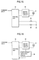
- Fig. 15 is a block diagram of a first modified example of the display device 1 according to the embodiment of the invention.
- this modified example there are provided limit switches 81, 83 for detecting closed and/or opened angular positions of the closing member 15 (here, for detecting a fully closed position and a fully opened position). Then, while detecting the rotating angular position (here, for detecting a fully closed position and a fully opened position) of the closing member 15 based on detection outputs from the limit switches 81, 83, the control unit 19 adjusts the opened position of the closing member 15 (here, the closing member 15 is designed to alternatively be opened and/or closed between the fully opened position and the fully closed position) . Due to this, there is no need to provide the motor 31 with an encoder in this modified example.
- a light source unit in which the backlights 72, 73 can be selectively turned on and off is provided on the back of the display unit 13 in the aforesaid embodiment
- a light source unit may be provided on the display unit 13 which is adapted to be illuminated at all times on the whole surface thereof to illuminate the whole surface of a screen 11 when the light source unit is turned on for implementing display.
- an area on the screen 11 which is covered with the closing member 15 and in which no display is implemented is displayed black.
- an EL display unit for example, an organic EL display unit
- the display unit 13 may be used as the display unit 13.
- the display unit since the display unit is installed in the accommodating portion provided in the dashboard portion and the display unit is constructed to emerge or submerge by opening or closing the opening of the accommodating portion with the closing member, the display unit being not constructed so as to be movable as in the case with the conventional display unit, even if touch switches are provided on the display unit, it is possible to prevent the supporting construction of the display unit from being affected by a load that would be generated when the touch switches are operated.
- the display device according to the embodiment of the invention can be installed even on an automotive vehicle which has less space in the interior of the dashboard portion.
- the opening width of the opening can be adjusted to the size of the display unit, there is no need to replace supporting units for display units every time a display unit of a different size is used, thereby making it possible to reduce the number of components used.
- the opening width of the opening in the accommodating portion is adjusted to the vertical width of a display area on the screen of the display unit which is actually used for required display, in a case where a large-sized display unit is used which can display a car navigation screen, when a simple display of information such as one on the operation of on-board equipment is sufficiently implemented on the narrow display area, the required display can be effected by allowing only a portion on the screen of the display unit which is sufficient for the display can be exposed to the driver or the like to thereby reduce the burden visually applied to the driver or the like.
- the opening width of the opening in the accommodating portion can be set accurately to any size based on an pulse output outputted from the motor.
- the opening width of the opening can be adjusted to the vertical width of the display area of the display unit where a display actually takes place in the state in which the opening in the accommodating portion is opened, the opening width of the accommodating portion can automatically be set to an appropriate size according to the vertical width of the display area.
- the backlights corresponding to the portions of the screen of the display unit which are exposed to the outside to implement required display are turned on, while the backlights corresponding to the portions on the screen which are not required for the display are constructed so as to be turned off, thereby making it possible to save the consumption of electric power.
- the first link members are connected to the closing member via the second link members and the third link members while the first to third three engagement projections provided on the second link members and the third link members are biased with the biasing means so that the three engagement projections are aligned with one another linearly
- the second arm portions of the second link members and the third link members rotate relative to each other against the biasing force of the biasing means such that the link members are arranged in substantially the "V" shape, whereby the excessive torque can be released.
- the closing member is located at the fully closed position or the fully opened position, the looseness of the closing member can be prevented by making use of the biasing force of the biasing means.
Landscapes
- Engineering & Computer Science (AREA)
- Mechanical Engineering (AREA)
- Chemical & Material Sciences (AREA)
- Combustion & Propulsion (AREA)
- Transportation (AREA)
- Fittings On The Vehicle Exterior For Carrying Loads, And Devices For Holding Or Mounting Articles (AREA)
- Instrument Panels (AREA)
Abstract
Description
- The present invention relates to an automotive display device installed in a dashboard portion of an automotive vehicle.
- As a conventional automotive display device related to the aforesaid type of automotive display device there exists an automotive display device comprising a pop-up type display unit which is supported so as emerge from and submerge into the interior of the dashboard portion by means of a predetermined movable mechanism, and in such a display device the display unit is often adapted to pop up from the interior of the dashboard portion only when it is in use in consideration of design or protection against dust.
- In addition, in this conventional automotive display device, the position of the display unit is alternatively changed over only between a popped-up state in which the front of a screen of the display unit has completely popped up on the dashboard and an accommodated state in which the display unit is accommodated in the dashboard, and therefore there has been conceived no construction in which the pop-up height of the display unit is changed in a stepped fashion. Consequently, the pop-up height of the display unit is predetermined according to the size (in particular, vertical size) of a display unit to be used and therefore it is fixed. Due to this, in the conventional pip-up type display device, the construction of a supporting unit for supporting a display unit so as to pop up is specific to the size of a display unit to be used.
- With the conventional automotive display device described above, since the display unit is driven and displaced so as to emerge and/or submerge, in a case where touch switches are provided on the display unit, there may be caused a problem that an operation load which is applied to the display unit through the operation of the touch switch acts on the movable mechanism of the display unit as a load to thereby affect the operation of the movable mechanism.
- In addition, with the conventional automotive display device, since the display unit is pulled downwardly so as to be accommodated in the interior of the dashboard portion, a space is required in the interior of the dashboard for accommodating the display unit therein, and this causes a problem that the installation of the display device in the dashboard portion cannot be realized unless there is much space secured in the interior of the dashboard portion of the vehicle.
- Furthermore, with the conventional automotive display device, in a case where display units of different sizes are used, the constructions of supporting units for supporting the display units have to be replaced, this causing a problem that an increase in the number of components is called for.
- In a case where a large-sized display unit is used which is large enough to display on its screen information on car navigation or the like, it is often the case with such a display unit that a single display unit is used to display not only information on the car navigation but also information on the operation of electric equipment such as an air conditioner and time. Since such a large display area is not usually required to display the information on the operation of the electric equipment and time, there is a demand that only a part of the display area on the screen of the display unit may be used to display such information.
- In this case, only an upper portion of the display area of the screen of the display unit may be allowed to pop up on the dashboard for displaying the required information. However, with the conventional automotive display device, since the whole of the screen of the display unit is designed to pop up on an upper surface of the dashboard when the display unit is put in the popped-up state, an unnecessary portion of the screen of the display unit also pops up on the dashboard to thereby be viewed by the driver, this causing a problem that the driver is forced to be burdened visually.
- The invention has been made in view of the aforesaid problems, and therefore a first object of the invention is to provide an automotive display device in which a display unit can be accommodated when not in use without making it movable.
- A second object of the invention is to provide an automotive display device which can also be installed on an automotive vehicle in which there is not much space in the interior of a dashboard portion thereof.
- A third object of the invention is to provide an automotive display device in which the opening width of an accommodating portion in which a display unit is installed can be set according to the size of the display unit or an area on the screen which is in use.
- With a view to attaining the objects above, according to a first aspect of the invention, preferably, there is provided an automotive display device installed in a dashboard portion of an automotive vehicle, comprising; a display unit installed in an accommodating portion provided in the dashboard portion, and a closing member provided on the dashboard portion for closing and/or opening an opening in the accommodating portion.
- According to a second aspect of the invention, preferably, there is provided an automotive display device as set forth in the first aspect of the invention, wherein the closing member is supported on the dashboard portion rotatably around a transverse shaft in such a manner as to close and/or open the opening in vertical directions, and wherein the automotive display device further comprises; a driving mechanism for driving the closing member to rotate based on the power of a motor to thereby open and/or close the closing member, and a control means for controlling the driving of the driving mechanism in response to an external input to thereby close and/or open the closing member and adjusting an opening width of the opening in a state in which the opening is left open.
- According to a third aspect of the invention, preferably there is provided an automotive display device as set forth in the second aspect of the invention, wherein the motor of the driving mechanism is a servo motor with an encoder, and wherein the control means adjusts the opening width of the opening to a predetermined value based on a pulse output outputted from the motor as the motor revolves.
- According to a fourth aspect of the invention, preferably there is provided an automotive display device as set forth in the second aspect of the invention, wherein the display unit has a function to vary a display area on a screen where display actually takes place, and wherein the control means adjusts the opening width of the opening to a vertical width of the display area of the screen of the display unit in the state in which the opening is left open.
- According to a fifth aspect of the invention, preferably, there is provided an automotive display device as set forth in the second aspect of the invention, wherein the display unit comprises; a liquid crystal display panel, and a light source unit having a plurality of backlights adapted to be switched on and/or off independently of each other and provided at positions on a back of said liquid crystal display panel which correspond, respectively, to a plurality of sub-areas obtained by vertically dividing the screen of the liquid crystal display panel into a plurality of areas, and wherein the control means adjust the opening width of the opening in such a manner as to expose to the outside the respective sub-areas of the screen of the display unit in a stepped fashion in the state in which the opening is left open.
- An automotive display device as set forth in Claim 2, wherein the driving mechanism comprises; a gear provided rotatably around a predetermined stationary transverse shaft located at a position of the closing member which is away from the rotating shaft of the closing member, the motor for driving the gear to rotate via a gear mechanism, a first link member adapted to rotate around said stationary transverse shaft together with the gear a second link member having first and second arm portions extending from a bend portion in two directions in such a manner as to form an L-shape when viewed from a side and pivotally connected at a distal end portion of said first arm portion thereof to a free end of said first link member, a third link member pivotally connected at one end thereof to the portion of the second link member and at the other end to the position of the closing member which is away from the rotating shaft of the closing member, a first engagement portion provided at the bend portion of the second link member or the one end of the third link member;
- a second engagement portion provided at a distal end portion of the second arm portion of the second link member,
- a third engagement portion provided at either the one end or the other end of the third link member such that a distance from the first engagement portion thereto becomes longer than a distance between the first and second engagement portions, and a biasing means adapted to be brought into engagement with the first, second and third engagement portions so as to bias the first, second and third engagement portions such that the first, second and third engagement portions are arranged linearly, wherein the power of the motor is transmitted to the closing member via the gear mechanism, said gear, said first link member, the second link member and said third link member, whereby the closing member is closed and/or opened.
-
-
- Fig. 1 is a partially cut-away side view of a main part of an automotive display device according to one embodiment of the invention;
- Fig. 2 is a plan view of Fig. 1;
- Fig. 3 is a front view of a center module in which the automotive display device shown in Fig. 1 is installed;
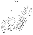
- Fig. 4 is a partially enlarged view of Fig. 1;
- Fig. 5 is a diagram showing a first link member;
- Fig. 6 is a diagram showing a second link member;
- Fig. 7 is a diagram showing a third link member;
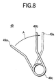
- Fig. 8 is a diagram showing a spring member;
- Fig. 9 is a diagram showing a state in which a closing member shown in Fig. 1 is fully opened;
- Fig. 10 is a diagram showing a state in which the closing member shown in Fig. 3 is fully opened;
- Fig. 11 is a diagram showing a state in which the closing member shown in Fig. 3 is fully closed;
- Fig. 12 is a block diagram of the automotive display device shown in Fig. 1;
- Fig. 13 is a typical view showing the construction of a display unit;
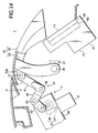
- Fig. 14 is a diagram showing a state in which a small-sized display unit is installed in the display unit shown in Fig. 1;
- Fig. 15 is a block diagram of a first modified example of the display device shown in Fig. 1; and
- Fig. 16 is a block diagram of a second modified example of the display device shown in Fig. 1.
-
- Now, a description will be given in more detail of preferred embodiments of the invention with reference to the accompanying drawings.
- Fig. 1 is a partially cut away side view of a main portion of an automotive vehicle display device according to one embodiment of the invention, Fig. 2 is a plan view of Fig. 1, and Fig. 3 is a front view of a center module in which the automotive display device of Fig. 1 is installed.
- As shown in Fig. 3, this
display device 1 is incorporated into thecenter module 3 which is installed in a dashboard central portion of an automotive vehicle. Namely, thecenter module 3 in this embodiment corresponds to a dashboard portion of the invention. Provided in an upper portion of thecenter module 3 is anaccommodating portion 5 in which thedisplay device 1 is incorporated and accommodated. Note thatreference numerals - As shown in Fig. 1, the
display device 1 comprises a display unit (display) 13 installed in theaccommodating portion 5 with ascreen 11 facing front seats, amovable closing member 15 for closing and/or opening an opening in theaccommodating portion 5, adriving mechanism 17 for driving theclosing member 15 to be closed and/or opened, a control portion (control means) 19 (refer to Fig. 13) for controlling the driving of saiddriving mechanism 17, and a central control portion 21 (refer to Fig. 13). Note that thiscentral control portion 21 may be omitted. - As shown in Figs. 1 and 2, the
closing member 15 comprises aframe member 23 and ahood member 25. Theframe member 23 is rotatably pin connected at distal end portions of left and right supportingarms 23a thereof to supportingmembers 27 provided on thecenter module 3 withpins 29, so that theframe member 23 is supported vertically rotatably around thepins 29 functioning as rotating shafts. Thehood member 25 is substantially a plate-like member which is fixed to theframe member 23 and opens and/or closes the opening of theaccommodating portion 5 as theframe member 23 rotates around thepins 29. - AS shown in Figs. 1 and 2, the
driving mechanism 17 comprises amotor 31, agear 33, areduction gear mechanism 35 for transmitting the rotating power of themotor 31 to thegear 33, and alink mechanism 37 for driving theclosing member 15 to be closed and/or opened based on the rotating power of thegear 33. Themotor 31, thegear 33 and thegear mechanism 35 are supported by a supportingmember 38 provided on thecenter module 3. Note that in Fig. 2 , as a matter of convenience, awarm gear 39 for themotor 31 and thegear mechanism 38 , which will be described later on, is omitted. - A pulse motor with a rotary encoder is used as the motor and outputs a pulse signal as said motor rotates.
- The
gear mechanism 35 comprises thewarm gear 39 mounted on a rotating shaft of the motor and atransmission gear 41 for transmitting the rotation of thewarm gear 39 to thegear 33. The transmission gear. 41 comprises a large-diameter gear portion 41a and a small-diameter gear portion 41b such that the large-diameter gear portion 41a mesh engages with thewarm gear 39, while the small-diameter gear portion 41b mesh engages with thegear 33. - The
gear 33 is supported on the supportingmember 38 in such a manner as to rotate around a transverse shaft and is designed to rotate around the transverse shaft when the rotating power of themotor 31 is given thereto via thegear mechanism 35. - As shown in Fig. 4, the
link mechanism 37 comprises first to third pairs oflink members link members 45, the left andright link members 45 are integrally connected by a connecting portion 51 (refer to Fig. 2). - As shown in Figs. 2, 4 and 5, the
first link member 43 is formed substantially into a rod-like shape, and a mountingportion 43b to ashaft 33a of thegear 33 which rotates together with thegear 33 is provided on one end portion (distal end portion) 43a of thelink member 43 and ahole 43d for connecting to thesecond link member 45 is formed in the other end portion (free end portion) 43c thereof. Then, when the mountingportion 43b is mounted on theshaft 33a, thelink member 43 is designed to rotate together with thegear 33 around the transverse shaft. - As shown in Figs. 2, 4 and 6, the
second link member 45 has first andsecond arm portions bend portion 45a in two directions in such a manner as to form an L-shape as viewed from a side. Ahole 45d is formed in thebend portion 45a for connecting to thethird link member 47, ahole 45e for connecting to thefirst link member 43 is formed in a distal end portion of thefirst arm portion 45b, and an engagement projection (second engagement portion) 45f is provided at a distal end portion of thesecond arm portion 45c in such a manner as to project inwards along a direction of the rotating axis of the closingmember 15. - As shown in Figs. 2, 4 and 7, the
third link member 47 is formed substantially into a rod-like shape. Ahole 47b is formed in oneend portion 47a of thethird link member 47 for connecting to thesecond link member 45 and ahole 47d for connecting to theframe member 23 of the closingmember 15 is formed in the other end portion thereof. In addition, formed in and provided at an intermediate portion of the link member is, respectively, anelongate hole 47e having a slightly elongate shape in a direction normal to a longitudinal direction of thelink member 47 and an engagement projection (third engagement portion ) 47f which projects inwards along a direction of the rotating axis of the closingmember 15. - Here, the
elongate hole 47e and theengagement projection 47f are, respectively, formed and provided on a straight line connecting theholes third link member 47. Theelongate hole 47e is formed in a position where theengagement projection 45 of thesecond link member 45 is loosely inserted when thehole 47b in theend portion 47a is connected to thehole 45d in thesecond link member 45 with apin 55. Theengagement portion 47f is provided at a position where a distance from thehole 47d thereto becomes longer than a distance from thehole 47d to theelongate hole 47e. - The
spring member 49 is a helical spring in which armportions wound portion 49c which is wound helically. - The connection of the
first link members 43 with thesecond link members 45 is effected by insertingpins 53 into theholes link members pins 53 acting as a transverse shaft. Note that in this embodiment the two link members are connected with each other such that thesecond link members 45 are positioned outwards of thefirst link members 43. - The connection of the
second link members 45 with thethird link members 47 is effected by inserting thepin 55 in theholes link members pin 55 acting as a transverse shaft. In this connected state, thesecond link members 45 are positioned outwards of thethird link members 47, and theengagement projections 45f of thesecond link members 45 project inwards of thethird link members 47 via theelongate holes 47e in thethird link members 47. - The connection of the
third link members 47 with theframe member 23 of the closingmember 15 is effected by inserting apin 57 in holes, not shown, in left and right connectingportions 23b of theframe member 23 and theholes 47d in thelink members 47, whereby thethird link members 47 are connected to the connectingportions 23b rotatably around thepin 57 acting as a transverse shaft. Note that the connectingportion 23b is provided at a position which is located away from a position where theframe member 23 is rotatably supported by the pin 29 (the distal end portion of the supportingarm 23a). - The mounting of the
spring member 49 is performed as below. With thepin 55 being inserted in thewound portion 49c of thespring member 49, the twoarm portions arm portions engagement projections engagement projections arm portions engagement projection 45f is biased by the twoarm portions spring member 49 so as to be positioned on a straight line connecting thepin 55 with theengagement projection 47f. Note that in this embodiment, thepin 55 corresponds to a first engagement portion according to the invention. - In this construction, when the
motor 31 is driven to rotate, the rotating power of themotor 31 is transmitted to thegear 33 via thegear mechanism 35, and as thegear 33 rotates, thefirst link members 43 are driven to rotate within a predetermined rotating angle range. As this occurs, the rotating power of thelink members 43 is then transmitted to the closingmember 15 via the second andthird link members link members 43 rotationally move, the closingmember 15 rotate around thepins 29, whereby the opening in theaccommodating portion 5 is closed and/or opened. - Here, Figs. 1, 2 and 3 show a state in which the closing
member 15 is opened such that the opening width of the opening in theaccommodating portion 5 becomes half a maximum opening width resulting when the closing member is fully opened, Figs. 9 and 10 show a state in which the closing member is opened such that the opening in theaccommodating portion 5 is fully opened, and Fig. 11 shows a state in which the opening in theaccommodating portion 5 is fully closed with the closingmember 15. - When the closing
member 15 is opened and/or closed as described above, in a normal state in which an excessive load is not applied to the closingmember 15, the power from thegear 33 is transmitted to the closingmember 15 via thelink mechanism 37 with thesecond arm portion 45c of thesecond link member 45 overlapping with thethird link member 47 linearly (that is, in a state in which thepin 55 and theengagement projections - On the contrary, in the event that an excessive load is applied to the closing
member 15 or the like when it is opened or closed, thesecond arm portion 45c of thesecond link member 45 and thethird link member 47 rotate relative to each other such that thepin 55 and theengagement projections springs 49, whereby the excessive torque is designed to be released. - In addition, when the closing
member 15 reaches a fully closed position and a fully opened position, a predetermined abutment portion, not shown, on the closingmember 15 is constructed to be brought into abutment with a predetermined abutment portion, not shown, on thecenter module 3, whereby the closingmember 15 is prevented from rotating further in the closing and opening directions. Due to this, the looseness of the closingmember 15 or the like resulting from a play can be prevented from occurring by constructing such that the closingmember 15 is biased toward the closing and opening directions using the biasing force of thespring members 49 when the closingmember 15 is fully closed and opened. - Fig. 12 is a block diagram of the automotive display device according to the embodiment of the invention. Responding to an opening or closing command given by a
central control unit 21, acontrol unit 19 detects a pulse output outputted from themotor 31 and controls the driving of themotor 31 via amotor driving circuit 69 to thereby open and/or close the closingmember 15, whereby the opening width of the opening in theaccommodating portion 5 is adjusted when the closingmember 15 is opened. Note that while thecontrol unit 19 is constructed to open and/or close the closingmember 15 in response to an opening or closing command outputted by thecentral control unit 21 in response in turn to an operation input directing to open or close the closingmember 15, thecontrol unit 19 may be constructed to directly respond to an operation input so as to open or close the closingmember 15 without providing thecentral control unit 21. - To be more specific, with the closing
member 15 being closed, when thecentral control unit 21 receives an operation input which directs to open the closingmember 15, thecentral control unit 21 outputs a command to open the closingmember 15 to thecontrol unit 19. As this occurs, an opening width of the opening in theaccommodating portion 5 which corresponds to the operation input is also adjusted by thecontrol unit 19. - Responding to the command from the
central control unit 21, while counting pulses given by themotor 31, thecontrol unit 19 drives themotor 31 via themotor driving circuit 69 until the number of pulses so counted reaches a value corresponding to a designated opening width, whereby the closingmember 15 is driven to be opened from the fully closed position to an open position corresponding to the designated opening width. As this occurs, the number of pulses counted is retained by thecontrol unit 19 until the closingmember 15 returns to the fully closed position again and is reset when thecontrol unit 19 detects the return of the closingmember 15 to the fully closed position. - In addition, when the closing
member 15 is fully opened, while counting pulses given by themotor 31, thecontrol unit 19 drives themotor 31 via themotor driving circuit 69 until the closing member reaches the fully opened position. As this occurs, that the closingmember 15 has reached the fully opened position is detected by detecting that the opening operation of the closingmember 15 has been stopped at the fully opened position, that even if driving pulses for driving themotor 31 are outputted further, there is no pulse outputted from the motor and hence the revolution of themotor 31 is at a halt. - On the other hand, with the closing
member 15 being opened at a predetermined open position, when thecentral control unit 21 receives an operation input directing to close the closingmember 15, thecentral control portion 21 outputs to the control unit 19 a command to close the closingmember 15. - Responding to the command from the
central control unit 21, while counting pulses given by themotor 31, thecontrol unit 19 drives themotor 31 via themotor driving circuit 69 until the closingmember 15 reaches the fully closed position. As this occurs, that the closingmember 15 has reached the fully closed position is detected by detecting that the closing operation of the closingmember 15 has been stopped at the fully closed position, that even if driving pulses for driving themotor 31 are outputted further, there is no pulse outputted from the motor and hence the revolution of themotor 31 is at a halt. - In addition, when the closing
member 15 is positioned at a position other than the fully closed position, the fully opened position or the designated open position, in the event that there is no pulse outputted from themotor 31 while being driven and hence the stop of revolution of themotor 31 is detected, the driving of the motor is stopped based on an understanding that something abnormal is happening in thedriving mechanism 17 such as the failure of thedriving mechanism 17 or the trapping of a foreign matter therein. - The
display unit 13 comprises a rectangular liquid crystal display panel (for example, a dot-matrix display type liquid crystal display panel) 61, alight source unit 63 disposed on a back side of the liquidcrystal display panel 61 and acontrol unit 65 for controlling the liquidcrystal display panel 61 and thelight source unit 63. These liquidcrystal display panel 61, thelight source unit 63 and thecontrol unit 65 are accommodated in acasing 67. Thescreen 11 of the liquidcrystal display panel 61 is divided vertically into a plurality of sub-areas (here, into two halves) at a position indicated by a chain double-dashed line in Fig. 13. Note that for thedisplay unit 13 according to the embodiment a large-sized display unit is adopted which can display television images and car navigation images. - To deal with the construction of the display unit described above, the
light source unit 63 comprises two sets ofbacklights upper portion area 11a and alower portion area 11b of thescreen 11, respectively. The respective sets ofbacklights control unit 65 such that thebacklights - In addition, to deal with the above construction, according to the embodiment of the invention, the opening width of the
accommodating portion 5 is constructed to change in a stepped fashion in accordance with the number of sub-areas resulting by the division of thescreen 11 of thedisplay unit 13. That is, in the embodiment, the closingmember 15 is constructed to be closed in a stepped fashion (in two steps) between the fully closed position shown in Fig. 11, an intermediately opened position as shown in Figs. 2 and 3 in which only thelower sub-area 11b of thescreen 11 of thedisplay unit 13 is exposed to the outside, and the fully opened position in which the whole of thescreen 11 is exposed to the outside. - When outputting an opening command to the
control unit 19, thecentral control unit 21 outputs to the display unit 13 a command designating a display area on the screen which corresponds to the opening width of the opening. Responding to the command, thecontrol unit 65 turns on thebacklights light source unit 63 corresponding to the designated display area, whereby an image is displayed using the sub-areas 11a, 11b of thescreen 11 of the liquidcrystal display panel 61. - Here, in a case where a car navigation image is displayed, the whole of the
screen 11 of thedisplay unit 13 is exposed to the outside from the opening in the accommodating 5, the whole of thescreen 11 of thedisplay unit 13 is used for displaying a required image. In addition, in a case where only simple information is displayed such as information on the operation of on-board equipment or information constituted by simple and easy characters or symbols, a narrow display area is sufficient for the purpose, only thelower sub-area 11b may be exposed to the outside from the opening in the accommodating portion so that only thelower sub-area 11b is used for the display. - Additionally, in the embodiment, while the large-sized display unit is used for the
display unit 13 which can display the car navigation information, as shown in Fig. 14, in a case where a small-sized display unit 71 is used to display information on the operation on the on-board equipment or information constituted by simple and easy characters and symbols, the opening width when the closingmember 15 is opened can be adjusted to the size of thescreen 11 of thedisplay unit 71. - As has been described heretofore, according to the embodiment of the invention, since the
display unit 13 is installed in theaccommodating portion 15 provided in thecenter module 3 and thedisplay unit 13 is designed to emerge or submerge by opening or closing the opening in the accommodating portion with the closingmember 15, thedisplay unit 13 therefore being not constructed so as be movable as in the case with the conventional display unit, even if there are provided touch switches on thedisplay unit 13, the supporting construction of thedisplay unit 13 can be prevented from being affected by a load that would be generated when operating the touch switches. - Additionally, since the conventional construction is not adopted in which the
display unit 13 is pulled downwards so as to be accommodated into the dashboard portion (the center module 3), thedisplay device 1 according to the embodiment of the invention can be installed even on an automotive vehicle which has less space in the interior of the dashboard portion. - Furthermore, since the opening width of the opening can be adjusted to the size of the display unit, there is no need to replace supporting units for display units every time a display unit of a different size is used, thereby making it possible to reduce the number of components used.
- In addition, since the opening width of the opening in the
accommodating portion 5 is adjusted to the vertical width of a display area on thescreen 11 of thedisplay unit 13 which is actually used for required display, in a case where a simple display of information such as one on the operation of on-board equipment is sufficiently implemented on the narrow display area, the required display can be effected by allowing only a portion on thescreen 11 of thedisplay unit 13 which is sufficient for the display can be exposed to the driver or the like to thereby reduce the burden visually applied to the driver or the like. - Furthermore, since the motor with an encoder is used for the
motor 31 for thedriving mechanism 17, the opening width of the opening in theaccommodating portion 5 can be set accurately to any size based on an pulse output outputted from themotor 31. - Additionally, since the opening width of the opening can be adjusted to the vertical width of the display area of the
display unit 13 where a display actually takes place in the state in which the opening in theaccommodating portion 5 is opened, the opening width of theaccommodating portion 5 can automatically be set to an appropriate size according to the vertical width of the display area of thedisplay unit 13. - Furthermore, only the
backlights screen 11 of thedisplay unit 13 which are exposed to the outside to implement required display are automatically turned on, while thebacklights screen 11 which are not required for the display are constructed so as to be automatically turned off, thereby making it possible to save the consumption of electric power. - Additionally, as has been described above, in the event that excessive torque is applied to the first to third embodiments when the closing
member 15 is opened and/or closed by virtue of the operation of thelink mechanism 37 having thespring members 29, the excessive torque can be released, and when the closingmember 15 is located at the fully opened position or the fully closed position, the looseness of the closingmember 15 can be prevented from by making use of the biasing force of thespring members 49. - Fig. 15 is a block diagram of a first modified example of the
display device 1 according to the embodiment of the invention. In this modified example, there are providedlimit switches member 15 based on detection outputs from the limit switches 81, 83, thecontrol unit 19 adjusts the opened position of the closing member 15 (here, the closingmember 15 is designed to alternatively be opened and/or closed between the fully opened position and the fully closed position) . Due to this, there is no need to provide themotor 31 with an encoder in this modified example. - While the
light source unit 63 in which thebacklights display unit 13 in the aforesaid embodiment, in another modified example, in a case where a liquidcrystal display panel 61 used is of a dot-matrix type such as using a TFT system, a light source unit may be provided on thedisplay unit 13 which is adapted to be illuminated at all times on the whole surface thereof to illuminate the whole surface of ascreen 11 when the light source unit is turned on for implementing display. In this case, when display is implemented, an area on thescreen 11 which is covered with the closingmember 15 and in which no display is implemented is displayed black. - In addition, while the liquid crystal display unit is used for the
display unit 13 in the aforesaid embodiment, an EL display unit (for example, an organic EL display unit) may be used as thedisplay unit 13. - According to the first to sixth aspect of the invention, since the display unit is installed in the accommodating portion provided in the dashboard portion and the display unit is constructed to emerge or submerge by opening or closing the opening of the accommodating portion with the closing member, the display unit being not constructed so as to be movable as in the case with the conventional display unit, even if touch switches are provided on the display unit, it is possible to prevent the supporting construction of the display unit from being affected by a load that would be generated when the touch switches are operated.
- Additionally, since the conventional construction is not adopted in which the display unit is pulled downwards so as to be accommodated into the dashboard portion, the display device according to the embodiment of the invention can be installed even on an automotive vehicle which has less space in the interior of the dashboard portion.
- According to the second aspect of the invention, since the opening width of the opening can be adjusted to the size of the display unit, there is no need to replace supporting units for display units every time a display unit of a different size is used, thereby making it possible to reduce the number of components used.
- In addition, since the opening width of the opening in the accommodating portion is adjusted to the vertical width of a display area on the screen of the display unit which is actually used for required display, in a case where a large-sized display unit is used which can display a car navigation screen, when a simple display of information such as one on the operation of on-board equipment is sufficiently implemented on the narrow display area, the required display can be effected by allowing only a portion on the screen of the display unit which is sufficient for the display can be exposed to the driver or the like to thereby reduce the burden visually applied to the driver or the like.
- According to the third aspect of the invention, since the motor an encoder is used for the motor for the driving mechanism, the opening width of the opening in the accommodating portion can be set accurately to any size based on an pulse output outputted from the motor.
- According to the fourth aspect of the invention, since the opening width of the opening can be adjusted to the vertical width of the display area of the display unit where a display actually takes place in the state in which the opening in the accommodating portion is opened, the opening width of the accommodating portion can automatically be set to an appropriate size according to the vertical width of the display area.
- According to the fifth aspect of the invention, only the backlights corresponding to the portions of the screen of the display unit which are exposed to the outside to implement required display are turned on, while the backlights corresponding to the portions on the screen which are not required for the display are constructed so as to be turned off, thereby making it possible to save the consumption of electric power.
- According to the sixth aspect of the invention, since the first link members are connected to the closing member via the second link members and the third link members while the first to third three engagement projections provided on the second link members and the third link members are biased with the biasing means so that the three engagement projections are aligned with one another linearly, in the event that the excessive torque is applied to the first to third link members or the like when the closing member is opened and/or closed, the second arm portions of the second link members and the third link members rotate relative to each other against the biasing force of the biasing means such that the link members are arranged in substantially the "V" shape, whereby the excessive torque can be released. Moreover, when the closing member is located at the fully closed position or the fully opened position, the looseness of the closing member can be prevented by making use of the biasing force of the biasing means.
Claims (7)
- An automotive display device installed in a dashboard portion of an automotive vehicle, comprising:a display unit installed in an accommodating portion provided in said dashboard portion; anda closing member provided on said dashboard portion for closing and/or opening an opening in said accommodating portion.
- The automotive display device as set forth in Claim 1, wherein said closing member is supported on said dashboard portion rotatably around a transverse shaft so as to close and/or open said opening in vertical directions; and
wherein said automotive display device further comprises: a driving mechanism for driving said closing member to rotate based on the power of a motor to thereby open and/or close said closing member; and a controller for controlling the driving of said driving mechanism in response to an external input to thereby close and/or open said closing member and adjusting an opening width of said opening in a state in which said opening is left open. - The automotive display device as set forth in Claim 2, wherein
said motor of said driving mechanism is a servo motor with an encoder; and wherein said controller adjusts the opening width of said opening to a predetermined value based on a pulse output outputted from said motor as said motor revolves. - The automotive display device as set forth in Claim 2, wherein said display unit has a function to vary a display area on a screen where display actually takes place; and
- wherein said controller adjusts the opening width of said opening to a vertical width of said display area of said screen of said display unit in the state in which said opening is left open.
- The automotive display device as set forth in Claim 2, wherein said display unit comprises: a liquid crystal display panel; and a light source unit having a plurality of backlights adapted to be switched on and/or off independently of each other and provided at positions on a back of said liquid crystal display panel which correspond, respectively, to a plurality of sub-areas obtained by vertically dividing said screen of said liquid crystal display panel into a plurality of areas; and
wherein said controller adjust the opening width of said opening in such a manner as to expose to the outside said respective sub-areas of said screen of said display unit in a stepped fashion in the state in which said opening is left open. - The automotive display device as set forth in Claim 2, wherein said driving mechanism comprises:a gear provided rotatably around a predetermined stationary transverse shaft located at a position of said closing member which is away from the rotating shaft of said closing member;said motor for driving said gear to rotate via a gear mechanism;a first link member adapted to rotate around said stationary transverse shaft together with said gear;a second link member having first and second arm portions extending from a bend portion in two directions so as to form an L-shape when viewed from a side and pivotally connected at a distal end portion of said first arm portion thereof to a free end of said first link member;a third link member pivotally connected at one end thereof to said bend portion of said second link member and at the other end to said position of said closing member which is away from the rotating shaft of said closing member;a first engagement portion provided at either said bend portion of said second link member or said one end of said third link member;a second engagement portion provided at a distal end portion of said second arm portion of said second link member;a third engagement portion provided at either said one end or said the other end of said third link member such that a distance from said first engagement portion thereto becomes longer than a distance between said first and second engagement portions; anda biasing member adapted to be brought into engagement with said first, second and third engagement portions so as to bias said first, second and third engagement portions such that said first, second and third engagement portions are arranged linearly;wherein the power of said motor is transmitted to said closing member via said gear mechanism, said gear, said first link member, said second link member and said third link member, whereby said closing member is closed and/or opened.
Applications Claiming Priority (2)
| Application Number | Priority Date | Filing Date | Title |
|---|---|---|---|
| JP2000133612 | 2000-05-02 | ||
| JP2000133612A JP3676188B2 (en) | 2000-05-02 | 2000-05-02 | Vehicle display device |
Publications (3)
| Publication Number | Publication Date |
|---|---|
| EP1151890A2 true EP1151890A2 (en) | 2001-11-07 |
| EP1151890A3 EP1151890A3 (en) | 2003-02-26 |
| EP1151890B1 EP1151890B1 (en) | 2006-04-19 |
Family
ID=18642072
Family Applications (1)
| Application Number | Title | Priority Date | Filing Date |
|---|---|---|---|
| EP01110592A Expired - Lifetime EP1151890B1 (en) | 2000-05-02 | 2001-04-30 | Automotive display device |
Country Status (4)
| Country | Link |
|---|---|
| US (1) | US6499788B2 (en) |
| EP (1) | EP1151890B1 (en) |
| JP (1) | JP3676188B2 (en) |
| DE (1) | DE60118829T2 (en) |
Cited By (2)
| Publication number | Priority date | Publication date | Assignee | Title |
|---|---|---|---|---|
| DE102005062316A1 (en) * | 2005-12-24 | 2007-06-28 | Fischer Automotive Systems Gmbh | Device for movably holding an input / output unit |
| TWI451988B (en) * | 2012-01-12 | 2014-09-11 | Taiwan Microelectronics Technologies Inc | Driving control system for vehicle |
Families Citing this family (32)
| Publication number | Priority date | Publication date | Assignee | Title |
|---|---|---|---|---|
| US6717287B2 (en) * | 2001-05-22 | 2004-04-06 | Visteon Global Technologies, Inc. | Input/output device for mounting in vehicle |
| KR100672635B1 (en) * | 2001-12-29 | 2007-01-23 | 엘지.필립스 엘시디 주식회사 | Driving Method of LCD |
| US6722718B2 (en) * | 2002-09-16 | 2004-04-20 | Intier Automotive Inc. | Latch mechanism for an automotive storage compartment |
| US7440845B1 (en) | 2003-03-26 | 2008-10-21 | Garmin Ltd. | Navigational device for installation in a vehicle and a method for doing same |
| US7650230B1 (en) | 2003-03-26 | 2010-01-19 | Garmin Ltd. | Navigational device for mounting on a support pillar of a vehicle and a method for doing same |
| US7623958B1 (en) | 2003-03-26 | 2009-11-24 | Garmin Ltd. | Navigational device for installation in a vehicle and a method for doing same |
| JP2006030950A (en) * | 2004-02-25 | 2006-02-02 | Fuji Photo Film Co Ltd | Cellulose acylate film, polarizing plate and liquid crystal display device |
| KR20070006752A (en) * | 2004-02-25 | 2007-01-11 | 후지 샤신 필름 가부시기가이샤 | Cellulose acylate film, polarizer and liquid crystal display |
| US7142980B1 (en) | 2004-04-29 | 2006-11-28 | Garmin Ltd. | Vehicle dash-mounted navigation device |
| DE102005003071B3 (en) * | 2005-01-22 | 2006-04-27 | Daimlerchrysler Ag | Display device e.g. for vehicle, has display for representing application data to vehicle user and pivot for moving display between positions and checks whether selected application data is permitted in actual state of vehicle |
| US7063370B2 (en) * | 2004-09-19 | 2006-06-20 | Lear Corporation | Automotive movable center stack panel with decorative surface linkage |
| DE112006000764B4 (en) * | 2005-05-26 | 2012-03-01 | Mitsubishi Electric Corp. | display device |
| US8002179B2 (en) * | 2005-12-20 | 2011-08-23 | Honda Motor Co., Ltd. | Hidden console display |
| US20090176103A1 (en) * | 2006-04-13 | 2009-07-09 | Takashi Arai | Gas Barrier Film |
| DE102006025383B3 (en) * | 2006-05-31 | 2007-12-13 | Siemens Ag | Board monitor device |
| DE102006025382B3 (en) * | 2006-05-31 | 2007-12-20 | Siemens Ag | Shutter device |
| ATE467530T1 (en) * | 2007-12-12 | 2010-05-15 | Bury Sp Zoo | HOLDER FOR A PORTABLE ELECTRONIC DEVICE, SPECIFICALLY FOR A VEHICLE DASHBOARD |
| US7862096B2 (en) * | 2008-07-31 | 2011-01-04 | Automotive Components Holdings, Llc | Upper glove box assembly |
| DE102010053344A1 (en) * | 2010-12-03 | 2012-06-06 | GM Global Technology Operations LLC | Screen in a vehicle interior |
| DE102011108938A1 (en) * | 2011-07-29 | 2013-01-31 | GM Global Technology Operations LLC (n. d. Gesetzen des Staates Delaware) | Holding device for fixing a portable driver information unit in the interior of a motor vehicle |
| JP5921173B2 (en) * | 2011-12-12 | 2016-05-24 | 富士通テン株式会社 | In-vehicle device and rotation method |
| JP6007731B2 (en) * | 2012-11-06 | 2016-10-12 | マツダ株式会社 | Mounting structure of vehicle information display device |
| JP6094366B2 (en) * | 2013-02-21 | 2017-03-15 | 豊田合成株式会社 | Damper opening and closing device |
| DE102013019571A1 (en) | 2013-11-22 | 2015-05-28 | Audi Ag | Swivel arrangement with overload protection |
| US10697505B2 (en) | 2016-06-01 | 2020-06-30 | Microsoft Technology Licensing, Llc | Clutch control |
| US10625688B2 (en) | 2017-11-06 | 2020-04-21 | Global Ip Holdings, Llc | Assembly capable of deploying an electronic device having a display screen in a vehicle |
| CN109177730B (en) * | 2018-09-26 | 2021-05-11 | 黄山市卓越仪器仪表有限公司 | Vacuum fluorescent display automobile combination instrument |
| DE202021105623U1 (en) * | 2020-10-15 | 2022-01-24 | Hyundai Mobis Co., Ltd. | Vehicle Cockpit Module Assembly |
| KR102878996B1 (en) * | 2020-10-15 | 2025-10-30 | 현대모비스 주식회사 | Vehicle sliding module assembly |
| KR102838053B1 (en) * | 2020-10-15 | 2025-07-24 | 현대모비스 주식회사 | Vehicle module assembly |
| KR102837116B1 (en) * | 2020-10-15 | 2025-07-23 | 현대모비스 주식회사 | Vehicle module assembly |
| CN116761736A (en) * | 2020-12-01 | 2023-09-15 | Tvs电机股份有限公司 | Instrument panel control system |
Family Cites Families (10)
| Publication number | Priority date | Publication date | Assignee | Title |
|---|---|---|---|---|
| US4312577A (en) * | 1979-08-13 | 1982-01-26 | Fitzgerald J Vincent | Motor vehicle map display system |
| US4706810A (en) * | 1986-05-02 | 1987-11-17 | Mako Marine, Inc. | Boat console system |
| DE4213129C2 (en) * | 1992-04-21 | 1996-01-25 | Audi Ag | Driver information system with a screen in a motor vehicle |
| US5823599A (en) * | 1995-09-06 | 1998-10-20 | Textron Automotive Company Inc. | Mechanized floor console |
| US6158795A (en) * | 1995-09-06 | 2000-12-12 | Textron Automotive Company, Inc. | Mechanized floor console |
| JPH1029446A (en) * | 1996-07-17 | 1998-02-03 | Mitsubishi Motors Corp | Display operation device for vehicles |
| JP3436039B2 (en) * | 1997-02-07 | 2003-08-11 | 日産自動車株式会社 | Layout structure of automotive display |
| JP3715804B2 (en) * | 1998-10-19 | 2005-11-16 | 小島プレス工業株式会社 | Openable interior device |
| JP2000132956A (en) * | 1998-10-23 | 2000-05-12 | Pioneer Electronic Corp | Vehicle-mounted equipment |
| US6152514A (en) * | 1998-12-10 | 2000-11-28 | Mclellen; Arthur O. | Resilient console for a passenger vehicle |
-
2000
- 2000-05-02 JP JP2000133612A patent/JP3676188B2/en not_active Expired - Fee Related
-
2001
- 2001-04-25 US US09/840,972 patent/US6499788B2/en not_active Expired - Fee Related
- 2001-04-30 DE DE60118829T patent/DE60118829T2/en not_active Expired - Fee Related
- 2001-04-30 EP EP01110592A patent/EP1151890B1/en not_active Expired - Lifetime
Non-Patent Citations (1)
| Title |
|---|
| None |
Cited By (3)
| Publication number | Priority date | Publication date | Assignee | Title |
|---|---|---|---|---|
| DE102005062316A1 (en) * | 2005-12-24 | 2007-06-28 | Fischer Automotive Systems Gmbh | Device for movably holding an input / output unit |
| US7685901B2 (en) | 2005-12-24 | 2010-03-30 | Fischer Automotive Systems Gmbh | Device for movable support of an input/output unit |
| TWI451988B (en) * | 2012-01-12 | 2014-09-11 | Taiwan Microelectronics Technologies Inc | Driving control system for vehicle |
Also Published As
| Publication number | Publication date |
|---|---|
| JP2001315585A (en) | 2001-11-13 |
| EP1151890B1 (en) | 2006-04-19 |
| EP1151890A3 (en) | 2003-02-26 |
| US20010042990A1 (en) | 2001-11-22 |
| JP3676188B2 (en) | 2005-07-27 |
| DE60118829T2 (en) | 2006-11-30 |
| US6499788B2 (en) | 2002-12-31 |
| DE60118829D1 (en) | 2006-05-24 |
Similar Documents
| Publication | Publication Date | Title |
|---|---|---|
| EP1151890B1 (en) | Automotive display device | |
| US5277172A (en) | Light source device for an endoscope | |
| EP1245449A3 (en) | In-vehicle display apparatus | |
| JP2005096579A (en) | Operating device for vehicular air-conditioner | |
| US12134352B2 (en) | Hybrid interior mirror with error recognition | |
| US6115008A (en) | Transparent EL display | |
| US11312304B2 (en) | Hybrid interior mirror with error recognition | |
| JPH1159224A (en) | Front window display device | |
| JP2004210019A (en) | Control operating device for air-conditioning of vehicle | |
| JPH03189620A (en) | On-vehicle liquid crystal display device | |
| JP2007157466A (en) | Operation device | |
| JP2001163033A (en) | Operating device for air conditioner | |
| JPH10172390A (en) | Operating device for vehicle air conditioner | |
| JP2007126049A (en) | Head-up display device | |
| JP4492505B2 (en) | Vehicle display device | |
| JP4332791B2 (en) | Heater control device for vehicle | |
| EP0174582B1 (en) | Ventilation device for motor vehicles | |
| JP4560767B2 (en) | Illuminated control knob device | |
| KR200144929Y1 (en) | Display device for normal operation by car ventilation mode | |
| EP4628342A2 (en) | Display apparatus for vehicle and driving method therefor | |
| EP3925828B1 (en) | Overhead console | |
| KR200246618Y1 (en) | Car television of roof mounted type | |
| JP2000052885A (en) | On-vehicle display device | |
| KR100402218B1 (en) | Car television of roof mounted type | |
| KR960004741Y1 (en) | Inside mirror angle adjuster of car |
Legal Events
| Date | Code | Title | Description |
|---|---|---|---|
| PUAI | Public reference made under article 153(3) epc to a published international application that has entered the european phase |
Free format text: ORIGINAL CODE: 0009012 |
|
| AK | Designated contracting states |
Kind code of ref document: A2 Designated state(s): AT BE CH CY DE DK ES FI FR GB GR IE IT LI LU MC NL PT SE TR |
|
| AX | Request for extension of the european patent |
Free format text: AL;LT;LV;MK;RO;SI |
|
| PUAL | Search report despatched |
Free format text: ORIGINAL CODE: 0009013 |
|
| AK | Designated contracting states |
Designated state(s): AT BE CH CY DE DK ES FI FR GB GR IE IT LI LU MC NL PT SE TR Kind code of ref document: A3 Designated state(s): AT BE CH CY DE DK ES FI FR GB GR IE IT LI LU MC NL PT SE TR |
|
| AX | Request for extension of the european patent |
Extension state: AL LT LV MK RO SI |
|
| RIC1 | Information provided on ipc code assigned before grant |
Ipc: 7B 60R 11/02 B Ipc: 7B 60K 35/00 B Ipc: 7B 60K 37/00 A Ipc: 7B 60Q 3/04 B |
|
| 17P | Request for examination filed |
Effective date: 20030331 |
|
| AKX | Designation fees paid |
Designated state(s): DE FR GB |
|
| 17Q | First examination report despatched |
Effective date: 20040420 |
|
| GRAP | Despatch of communication of intention to grant a patent |
Free format text: ORIGINAL CODE: EPIDOSNIGR1 |
|
| GRAS | Grant fee paid |
Free format text: ORIGINAL CODE: EPIDOSNIGR3 |
|
| GRAA | (expected) grant |
Free format text: ORIGINAL CODE: 0009210 |
|
| AK | Designated contracting states |
Kind code of ref document: B1 Designated state(s): DE FR GB |
|
| REG | Reference to a national code |
Ref country code: GB Ref legal event code: FG4D |
|
| PGFP | Annual fee paid to national office [announced via postgrant information from national office to epo] |
Ref country code: DE Payment date: 20060427 Year of fee payment: 6 |
|
| REF | Corresponds to: |
Ref document number: 60118829 Country of ref document: DE Date of ref document: 20060524 Kind code of ref document: P |
|
| PG25 | Lapsed in a contracting state [announced via postgrant information from national office to epo] |
Ref country code: GB Free format text: LAPSE BECAUSE OF NON-PAYMENT OF DUE FEES Effective date: 20060719 |
|
| PLBE | No opposition filed within time limit |
Free format text: ORIGINAL CODE: 0009261 |
|
| STAA | Information on the status of an ep patent application or granted ep patent |
Free format text: STATUS: NO OPPOSITION FILED WITHIN TIME LIMIT |
|
| 26N | No opposition filed |
Effective date: 20070122 |
|
| GBPC | Gb: european patent ceased through non-payment of renewal fee |
Effective date: 20060719 |
|
| EN | Fr: translation not filed | ||
| PG25 | Lapsed in a contracting state [announced via postgrant information from national office to epo] |
Ref country code: DE Free format text: LAPSE BECAUSE OF NON-PAYMENT OF DUE FEES Effective date: 20071101 |
|
| PG25 | Lapsed in a contracting state [announced via postgrant information from national office to epo] |
Ref country code: FR Free format text: LAPSE BECAUSE OF FAILURE TO SUBMIT A TRANSLATION OF THE DESCRIPTION OR TO PAY THE FEE WITHIN THE PRESCRIBED TIME-LIMIT Effective date: 20070309 |
|
| PG25 | Lapsed in a contracting state [announced via postgrant information from national office to epo] |
Ref country code: FR Free format text: LAPSE BECAUSE OF FAILURE TO SUBMIT A TRANSLATION OF THE DESCRIPTION OR TO PAY THE FEE WITHIN THE PRESCRIBED TIME-LIMIT Effective date: 20060430 |
|
| PG25 | Lapsed in a contracting state [announced via postgrant information from national office to epo] |
Ref country code: FR Free format text: LAPSE BECAUSE OF FAILURE TO SUBMIT A TRANSLATION OF THE DESCRIPTION OR TO PAY THE FEE WITHIN THE PRESCRIBED TIME-LIMIT Effective date: 20060419 |