EP1151829A2 - Schlauchführung im Sockel eines Roboters - Google Patents
Schlauchführung im Sockel eines Roboters Download PDFInfo
- Publication number
- EP1151829A2 EP1151829A2 EP01110656A EP01110656A EP1151829A2 EP 1151829 A2 EP1151829 A2 EP 1151829A2 EP 01110656 A EP01110656 A EP 01110656A EP 01110656 A EP01110656 A EP 01110656A EP 1151829 A2 EP1151829 A2 EP 1151829A2
- Authority
- EP
- European Patent Office
- Prior art keywords
- hose
- base
- arm
- robot
- carousel
- Prior art date
- Legal status (The legal status is an assumption and is not a legal conclusion. Google has not performed a legal analysis and makes no representation as to the accuracy of the status listed.)
- Granted
Links
Images

Classifications
-
- H—ELECTRICITY
- H02—GENERATION; CONVERSION OR DISTRIBUTION OF ELECTRIC POWER
- H02G—INSTALLATION OF ELECTRIC CABLES OR LINES, OR OF COMBINED OPTICAL AND ELECTRIC CABLES OR LINES
- H02G11/00—Arrangements of electric cables or lines between relatively-movable parts
-
- B—PERFORMING OPERATIONS; TRANSPORTING
- B25—HAND TOOLS; PORTABLE POWER-DRIVEN TOOLS; MANIPULATORS
- B25J—MANIPULATORS; CHAMBERS PROVIDED WITH MANIPULATION DEVICES
- B25J19/00—Accessories fitted to manipulators, e.g. for monitoring, for viewing; Safety devices combined with or specially adapted for use in connection with manipulators
- B25J19/0025—Means for supplying energy to the end effector
- B25J19/0029—Means for supplying energy to the end effector arranged within the different robot elements
-
- H—ELECTRICITY
- H01—ELECTRIC ELEMENTS
- H01R—ELECTRICALLY-CONDUCTIVE CONNECTIONS; STRUCTURAL ASSOCIATIONS OF A PLURALITY OF MUTUALLY-INSULATED ELECTRICAL CONNECTING ELEMENTS; COUPLING DEVICES; CURRENT COLLECTORS
- H01R35/00—Flexible or turnable line connectors, i.e. the rotation angle being limited
- H01R35/02—Flexible line connectors without frictional contact members
- H01R35/025—Flexible line connectors without frictional contact members having a flexible conductor wound around a rotation axis
Definitions
- the invention relates to a hose guide in the base of a Robot, with a hose with a lower and with a upper hose arm by a curved hose head are interconnected.
- the carousel can be rotated around the A1 axis of the robot Provide a reserve relative to the fixed base his.
- they are in the robot base in hoses, in usually in the form of ribbed tubes that are aligned vertically so that from an introductory a lower hose arm is guided along the base of the base is into a vertically curved hose head and from this into an upper tube arm along the Bottom of the carousel to an exit opening in it to continue the cables along the robot.
- the lower and upper hose arm are exactly vertical overlapped.
- This cable protection hose is on the Outer wall of the robot base and that along the there given coat cover led. This means that they Grind along the base coat, causing wear with the necessary effort for monitoring, repeated replacement and thus standstill and increased Setup times of the robot results.
- the Height of the plinth alone through the required minimum bending radius the cable protection conduits and through them guided cable is therefore considerable and especially larger than that due to other more constructive Features of the robot in the area of the robot base, such as the gearbox, required height.
- the invention is therefore based on the object while avoiding an improved of the aforementioned disadvantages To create a hose guide.
- the stated task is at a Hose guide of the type mentioned above solved that the upper hose arm is relative to the lower hose arm is offset from the vertical axis of the base.
- the upper hose arm in a groove of the carousel of the robot which has a smaller diameter has the inclusion of the lower hose arm on the base of the Robot. This ensures that the hose is guided safely, especially the upper hose arm.
- In Training can be provided that the carousel surrounding the upper hose arm, opposite this (then in the upper area) lowered radially directed Has ring flange, the ring flange in particular lowered compared to the groove receiving the upper hose arm is.
- Another embodiment sees a partially conical Coat of the base in front. This will make the base more optimal Stand area in particular a more pleasing appearance awarded, while continuing to reduce the upper area of the base and thus the carousel area a material saving is achieved without the a pedestal sitting on the floor with a view to the stability must have a reduced area.
- FIG. 1 shows a known robot in a side view with a cylindrical base.
- 2 shows a section the base of the robot of Fig. 1. It can be seen that the cable hoses on the right and left are U-shaped are, with a U-web is aligned vertically and the U-legs of the hoses exactly vertically one above the other lie.
- FIG. 3 shows, partially broken, the lower area of a robot 1 designed according to the invention with a stationary one Base 2, consisting of a base core 3 and optionally a base jacket 4. On the base core 3 and carried by this is rotatably driven over a Gear 6 the carousel 7 of the robot with a carousel plate 8.
- the further structure is on this of the robot, such as a motor for driving the carousel plate 8, a linkage with which the swing arm around the A2 axis of the Articulation is movable, and if necessary a torque compensation for the swingarm.
- hose 9 In the robot shown, there is a base 2 Hose 9 and possibly a hose 11.
- the hose 9 which is usually designed as a ribbed tube, are cables 9a for supplying power to the various drives of the robot, while in the hose 11 if necessary Cable 11a for the power supply of a tool of the robot.
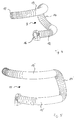
- the hoses 9.11 are made as explained using the hose 9, from a lower Hose arm 12 and an upper hose arm 13, which over a hose head 14 (Fig. 4) are interconnected.
- the hose arm 13 is higher than the hose arm 12.
- Das free end 16 of the lower hose arm 12 is arranged in a stationary manner, this is where the power supply cables are introduced from outside.
- the free end 17 of the top Hose arm 13 is fixedly movable with respect to base 2 Carousel 7 connected, so changes with movements the robot or more precisely the carousel 7 of the same its position to the inlet end 16 of the hose 9.
- the Hose 9 forms a total length reserve for compensation the required hose length with relative movement of the carousel 7 relative to the base 2.
- the hose 11 is made accordingly from the lower hose arm 12 ', hose head 12 'and upper hose arm 13' (Fig. 5).
- FIGS. 3 to 5 showing the invention that that the upper hose arm 13, 13 'is not exact is vertically above the lower hose arm 12, 12 ', like this is the case with the prior art, but the Hose arm 13 relative to hose arm 12 for vertical A1 axis of the robot, i.e. offset radially inwards is arranged and accordingly also a smaller radius of curvature has than the hose arm 12, 12 '.
- the Hose arm 13 relative to hose arm 12 for vertical A1 axis of the robot i.e. offset radially inwards is arranged and accordingly also a smaller radius of curvature has than the hose arm 12, 12 '.
- the upper hose arm 13, 13 ' is in a groove 18 of the Carousels guided, which are also offset to the A1 axis and thus is offset radially inwards compared to one groove-like receptacle 19 in the lower region of the base core 3 for the lower hose arm 12.
- a radially directed ring plate 21 may be provided, the lowered relative to the horizontal inner wall of the groove 18 is; the height of the horizontal inner wall 22 of the Groove 18 is the required minimum bending radii of the Determined hose, which has a large height and therefore one Arrangement of the wall 22 above the floor require that the Height of the wall 22 through the hose and its minimum bending radii is specified.
- the ring plate 21 which is lowered relative to the wall 22 is provided outside the groove 18 so that on its upper This leaves space for additional elements such as for example the continuation of the hose outside the Base 2 is given; moreover, by the invention Oblique arrangement of the hose guide on the one hand reduces the actual effective height of the base, because the hose head is arranged obliquely and therefore at same bending radius takes up a lower overall height. Also is the optical height of the base in the design 1 reduced by the lowered ring plate 21, what the robot base compared to conventional high bases gives a more appealing look. This is about further supported if, as shown in FIG.
- the base wall of the inclined hose guide follows the side wall 4 'of the base 2 there is conical or truncated cone-shaped.
- the base peripheral wall 4 can also be aligned vertically be and complete with the outer edge of the ring plate 21.
Landscapes
- Engineering & Computer Science (AREA)
- Robotics (AREA)
- Mechanical Engineering (AREA)
- Manipulator (AREA)
Abstract
Description
- Fig. 1
- einen bekannten Roboter in Seitenansicht;
- Fig. 2
- eine Ausführungsform des Sockels eines bekannten Roboters im Schnitt;
- Fig. 3
- eine bevorzugte Ausgestaltung des Erfindungsgegenstandes mit abgesenktem Radialflansch am Karussell eines Roboters und kegelstumpfförmig ausgebildetem Sockel;
- Fig. 4
- eine Darstellung der erfindungsgemäßen Führung eines Schlauchs für die Kabel zur Energieversorgung der Roboterantriebe in einem Robotersockel mit Versatz vom oberen zum unteren Schlaucharm; und
- Fig. 5
- eine Darstellung der erfindungsgemäßen Führung eines Schlauchs für Kabel zur Energieversorgung.
- 1
- Roboter
- 2
- Sockel
- 3
- Sockelkern
- 4,4a
- Sockelmantel
- 4'
- Seitenwandung
- 6
- Getriebe
- 7
- Karussell
- 8
- Karussellplatte
- 9
- Schlauch
- 11
- Schlauch
- 12
- Schlaucharm
- 13
- Schlaucharm
- 14
- Schlauchkopf
- 16
- freies Ende
- 17
- freies Ende
- 18
- Nut
- 19
- Aufnahme
- 21
- Ringflansch
- 22
- Innenwandung
- A1
- A1-Achse
Claims (5)
- Schlauchführung im Sockel (2) eines Roboters (1), mit einem Schlauch (9) mit einem unteren und mit einem oberen Schlaucharm (12,13), die durch einen gebogenen Schlauchkopf miteinander verbunden sind, dadurch gekennzeichnet, dass der obere Schlauch (12) relativ zum unteren Schlaucharm (13) in horizontaler Richtung hin versetzt geführt ist.
- Schlauchführung nach Anspruch 1, dadurch gekennzeichnet, dass der obere Schlaucharm (13) relativ zum unteren Schlaucharm (12) zur vertikalen Achse (A1-Achse) des Sockels (2) hin versetzt ist.
- Schlauchführung nach Anspruch 1 oder 2, dadurch gekennzeichnet, dass der obere Schlaucharm (13) in einer Nut (18) des Karussells (7) des Roboters (1) geführt ist, die einen geringeren Durchmesser hat als die Aufnahme (19) des unteren Schlaucharms (12) am Sockel (2) des Roboters (1).
- Schlauchführung nach einem der vorangehenden Ansprüche, dadurch gekennzeichnet, dass das Karussell (7) einen den oberen Schlaucharm (13) umgebenen, gegenüber diesem (dann im oberen Bereich) abgesenkten radial gerichteten Ringflansch (21) aufweist.
- Schlauchführung nach einem der vorangehenden Ansprüche, gekennzeichnet durch einen teilkegelförmigen Mantel (4a) des Sockels (2).
Applications Claiming Priority (2)
| Application Number | Priority Date | Filing Date | Title |
|---|---|---|---|
| DE20008054U DE20008054U1 (de) | 2000-05-05 | 2000-05-05 | Schlauchführung im Sockel eines Roboters |
| DE20008054U | 2000-05-05 |
Publications (3)
| Publication Number | Publication Date |
|---|---|
| EP1151829A2 true EP1151829A2 (de) | 2001-11-07 |
| EP1151829A3 EP1151829A3 (de) | 2004-01-21 |
| EP1151829B1 EP1151829B1 (de) | 2006-05-31 |
Family
ID=7941059
Family Applications (1)
| Application Number | Title | Priority Date | Filing Date |
|---|---|---|---|
| EP01110656A Expired - Lifetime EP1151829B1 (de) | 2000-05-05 | 2001-05-02 | Schlauchführung im Sockel eines Roboters |
Country Status (3)
| Country | Link |
|---|---|
| US (1) | US20020029815A1 (de) |
| EP (1) | EP1151829B1 (de) |
| DE (2) | DE20008054U1 (de) |
Families Citing this family (4)
| Publication number | Priority date | Publication date | Assignee | Title |
|---|---|---|---|---|
| DE10216081B4 (de) | 2002-04-11 | 2005-03-31 | Kabelschlepp Gmbh | Roboter mit einer Leitungsführungseinrichtung |
| DE202008011282U1 (de) | 2008-08-25 | 2010-02-11 | Kräutner Sondermaschinenbau GmbH | Sockel für einen Roboter |
| JP4837117B2 (ja) * | 2010-04-14 | 2011-12-14 | ファナック株式会社 | ロボットアーム部の線条体配設機構 |
| JP4865882B2 (ja) * | 2010-04-16 | 2012-02-01 | ファナック株式会社 | ロボット手首部の線条体配設機構 |
Family Cites Families (5)
| Publication number | Priority date | Publication date | Assignee | Title |
|---|---|---|---|---|
| DE9200618U1 (de) * | 1992-01-20 | 1992-04-23 | Kuka Schweissanlagen + Roboter Gmbh, 8900 Augsburg | Mehrachsiger Roboter |
| DE4214863A1 (de) * | 1992-05-05 | 1993-11-11 | Kuka Schweissanlagen & Roboter | Verfahren und Vorrichtung zur Montage von Türen in Fahrzeugkarosserien |
| US5694813A (en) * | 1996-09-23 | 1997-12-09 | Nachi Robotics Systems Inc. | Industrial robot |
| DE19850452B4 (de) * | 1997-11-07 | 2013-12-12 | Nachi-Fujikoshi Corp. | Haltevorrichtung für Schaltverbindungen und Rohrleitungen eines Industrieroboters |
| SE511643C2 (sv) * | 1998-10-16 | 1999-11-01 | Abb Ab | Styrning av yttre kablage för industrirobot |
-
2000
- 2000-05-05 DE DE20008054U patent/DE20008054U1/de not_active Expired - Lifetime
-
2001
- 2001-05-02 DE DE50109923T patent/DE50109923D1/de not_active Expired - Lifetime
- 2001-05-02 EP EP01110656A patent/EP1151829B1/de not_active Expired - Lifetime
- 2001-05-03 US US09/848,183 patent/US20020029815A1/en not_active Abandoned
Also Published As
| Publication number | Publication date |
|---|---|
| EP1151829B1 (de) | 2006-05-31 |
| US20020029815A1 (en) | 2002-03-14 |
| DE20008054U1 (de) | 2001-06-21 |
| EP1151829A3 (de) | 2004-01-21 |
| DE50109923D1 (de) | 2006-07-06 |
Similar Documents
| Publication | Publication Date | Title |
|---|---|---|
| EP2580031B1 (de) | Robotermodul | |
| DE3631024C2 (de) | ||
| DE102012219881B4 (de) | Endoskopisches Instrument | |
| EP2874548B1 (de) | Endoskopisches instrument | |
| EP2461948B1 (de) | Parallelroboter | |
| EP2321097B1 (de) | Gelenkarmroboter mit u-förmiger basis | |
| DE102018102686B4 (de) | Horizontal-Gelenk-Roboter | |
| DE2251808C3 (de) | Zahnärztlicher Patientenstuhl mit Parallelogrammtragarm | |
| EP0691118A2 (de) | Stützsäule zur Halterung einer Patientenlagerfläche | |
| EP0054763A1 (de) | Getriebeanordnung für einen mit dem Ausleger eines Manipulators verbundenen Gelenkkopf | |
| EP0123221B1 (de) | Handhabungssystem, insbesondere für kleine Lasten und/oder begrenzte Zugriffswege | |
| DE2913311A1 (de) | Sicherheitskupplung fuer motorisch betriebene biegsame wellen | |
| DE102012002093A1 (de) | Leitungsführungssystem zur Aufnahme und Führung von Versorgungsleitungen sowie Werkzeugmaschine | |
| DE2635197A1 (de) | Scherenhebetisch | |
| DE19526596B4 (de) | Scherenhubtisch | |
| EP1151829B1 (de) | Schlauchführung im Sockel eines Roboters | |
| EP4376728B1 (de) | Chirurgisches instrument und lenkgetriebe dafür | |
| DE3311094A1 (de) | Vorrichtung zum transportieren von gegenstaenden bzw. zum selbstfortbewegen | |
| EP0496994B1 (de) | Stativ | |
| AT501265B1 (de) | Hand bzw. finger für einen roboter | |
| EP2277730A1 (de) | Antriebseinheit für eine Windstopeinrichtung | |
| DE3126095A1 (de) | Leitungshalterung fuer leitungen an einem gelenkfahrzeug, insbesondere einem gelenkbus | |
| DE10227261A1 (de) | Mäh- und/oder Schneidgerät | |
| EP0552688B1 (de) | Mehrachsiger Roboter | |
| WO2022096730A1 (de) | Ausgabevorrichtung für eine flexible leitungsanordnung und leitungsführungseinrichtung mit fördereinheit |
Legal Events
| Date | Code | Title | Description |
|---|---|---|---|
| PUAI | Public reference made under article 153(3) epc to a published international application that has entered the european phase |
Free format text: ORIGINAL CODE: 0009012 |
|
| AK | Designated contracting states |
Kind code of ref document: A2 Designated state(s): AT BE CH CY DE DK ES FI FR GB GR IE IT LI LU MC NL PT SE TR |
|
| AX | Request for extension of the european patent |
Free format text: AL;LT;LV;MK;RO;SI |
|
| PUAL | Search report despatched |
Free format text: ORIGINAL CODE: 0009013 |
|
| AK | Designated contracting states |
Kind code of ref document: A3 Designated state(s): AT BE CH CY DE DK ES FI FR GB GR IE IT LI LU MC NL PT SE TR |
|
| AX | Request for extension of the european patent |
Extension state: AL LT LV MK RO SI |
|
| 17P | Request for examination filed |
Effective date: 20040714 |
|
| AKX | Designation fees paid |
Designated state(s): DE FR GB IT SE |
|
| GRAP | Despatch of communication of intention to grant a patent |
Free format text: ORIGINAL CODE: EPIDOSNIGR1 |
|
| GRAS | Grant fee paid |
Free format text: ORIGINAL CODE: EPIDOSNIGR3 |
|
| GRAA | (expected) grant |
Free format text: ORIGINAL CODE: 0009210 |
|
| AK | Designated contracting states |
Kind code of ref document: B1 Designated state(s): DE FR GB IT SE |
|
| PG25 | Lapsed in a contracting state [announced via postgrant information from national office to epo] |
Ref country code: IT Free format text: LAPSE BECAUSE OF FAILURE TO SUBMIT A TRANSLATION OF THE DESCRIPTION OR TO PAY THE FEE WITHIN THE PRESCRIBED TIME-LIMIT;WARNING: LAPSES OF ITALIAN PATENTS WITH EFFECTIVE DATE BEFORE 2007 MAY HAVE OCCURRED AT ANY TIME BEFORE 2007. THE CORRECT EFFECTIVE DATE MAY BE DIFFERENT FROM THE ONE RECORDED. Effective date: 20060531 Ref country code: GB Free format text: LAPSE BECAUSE OF FAILURE TO SUBMIT A TRANSLATION OF THE DESCRIPTION OR TO PAY THE FEE WITHIN THE PRESCRIBED TIME-LIMIT Effective date: 20060531 |
|
| REG | Reference to a national code |
Ref country code: GB Ref legal event code: FG4D Free format text: NOT ENGLISH |
|
| REF | Corresponds to: |
Ref document number: 50109923 Country of ref document: DE Date of ref document: 20060706 Kind code of ref document: P |
|
| REG | Reference to a national code |
Ref country code: SE Ref legal event code: TRGR |
|
| GBV | Gb: ep patent (uk) treated as always having been void in accordance with gb section 77(7)/1977 [no translation filed] |
Effective date: 20060531 |
|
| PLBE | No opposition filed within time limit |
Free format text: ORIGINAL CODE: 0009261 |
|
| STAA | Information on the status of an ep patent application or granted ep patent |
Free format text: STATUS: NO OPPOSITION FILED WITHIN TIME LIMIT |
|
| EN | Fr: translation not filed | ||
| 26N | No opposition filed |
Effective date: 20070301 |
|
| PG25 | Lapsed in a contracting state [announced via postgrant information from national office to epo] |
Ref country code: FR Free format text: LAPSE BECAUSE OF FAILURE TO SUBMIT A TRANSLATION OF THE DESCRIPTION OR TO PAY THE FEE WITHIN THE PRESCRIBED TIME-LIMIT Effective date: 20070309 |
|
| PG25 | Lapsed in a contracting state [announced via postgrant information from national office to epo] |
Ref country code: FR Free format text: LAPSE BECAUSE OF FAILURE TO SUBMIT A TRANSLATION OF THE DESCRIPTION OR TO PAY THE FEE WITHIN THE PRESCRIBED TIME-LIMIT Effective date: 20060531 |
|
| REG | Reference to a national code |
Ref country code: DE Ref legal event code: R082 Ref document number: 50109923 Country of ref document: DE |
|
| REG | Reference to a national code |
Ref country code: DE Ref legal event code: R081 Ref document number: 50109923 Country of ref document: DE Owner name: KUKA DEUTSCHLAND GMBH, DE Free format text: FORMER OWNER: KUKA ROBOTER GMBH, 86165 AUGSBURG, DE |
|
| PGFP | Annual fee paid to national office [announced via postgrant information from national office to epo] |
Ref country code: DE Payment date: 20200422 Year of fee payment: 20 |
|
| PGFP | Annual fee paid to national office [announced via postgrant information from national office to epo] |
Ref country code: SE Payment date: 20200512 Year of fee payment: 20 |
|
| REG | Reference to a national code |
Ref country code: DE Ref legal event code: R071 Ref document number: 50109923 Country of ref document: DE |
|
| REG | Reference to a national code |
Ref country code: SE Ref legal event code: EUG |