EP1151800A2 - Silenced nozzle for discharge of extinguishing gas - Google Patents
Silenced nozzle for discharge of extinguishing gas Download PDFInfo
- Publication number
- EP1151800A2 EP1151800A2 EP00126770A EP00126770A EP1151800A2 EP 1151800 A2 EP1151800 A2 EP 1151800A2 EP 00126770 A EP00126770 A EP 00126770A EP 00126770 A EP00126770 A EP 00126770A EP 1151800 A2 EP1151800 A2 EP 1151800A2
- Authority
- EP
- European Patent Office
- Prior art keywords
- nozzle
- extinguishing gas
- hole
- gas
- filter assembly
- Prior art date
- Legal status (The legal status is an assumption and is not a legal conclusion. Google has not performed a legal analysis and makes no representation as to the accuracy of the status listed.)
- Withdrawn
Links
Images



Classifications
-
- B—PERFORMING OPERATIONS; TRANSPORTING
- B05—SPRAYING OR ATOMISING IN GENERAL; APPLYING FLUENT MATERIALS TO SURFACES, IN GENERAL
- B05B—SPRAYING APPARATUS; ATOMISING APPARATUS; NOZZLES
- B05B1/00—Nozzles, spray heads or other outlets, with or without auxiliary devices such as valves, heating means
- B05B1/002—Nozzles, spray heads or other outlets, with or without auxiliary devices such as valves, heating means designed to reduce the generation or the transmission of noise or to produce a particular sound; associated with noise monitoring means
-
- A—HUMAN NECESSITIES
- A62—LIFE-SAVING; FIRE-FIGHTING
- A62C—FIRE-FIGHTING
- A62C31/00—Delivery of fire-extinguishing material
- A62C31/02—Nozzles specially adapted for fire-extinguishing
- A62C31/05—Nozzles specially adapted for fire-extinguishing with two or more outlets
-
- A—HUMAN NECESSITIES
- A62—LIFE-SAVING; FIRE-FIGHTING
- A62C—FIRE-FIGHTING
- A62C99/00—Subject matter not provided for in other groups of this subclass
- A62C99/0009—Methods of extinguishing or preventing the spread of fire by cooling down or suffocating the flames
- A62C99/0018—Methods of extinguishing or preventing the spread of fire by cooling down or suffocating the flames using gases or vapours that do not support combustion, e.g. steam, carbon dioxide
-
- B—PERFORMING OPERATIONS; TRANSPORTING
- B05—SPRAYING OR ATOMISING IN GENERAL; APPLYING FLUENT MATERIALS TO SURFACES, IN GENERAL
- B05B—SPRAYING APPARATUS; ATOMISING APPARATUS; NOZZLES
- B05B1/00—Nozzles, spray heads or other outlets, with or without auxiliary devices such as valves, heating means
- B05B1/005—Nozzles or other outlets specially adapted for discharging one or more gases
Definitions
- the present invention refers to a silenced nozzle for the discharge of extinguishing gases, particularly suitable for application to fire fighting systems that work with a gaseous-type extinguishing fluid.
- Fire extinguishing systems that use a gaseous fluid as the extinguishing fluid are known to the art. By means of dispensing nozzles this gaseous fluid is delivered at high pressure onto the flames to inhibit them.
- the maximum recommended threshold for noise measured in a working environment is 90 dB.
- a discharge of gas from the nozzles of the fire extinguishing system may occur erroneously; as a result all the operators are obliged to abandon the workplace because of the unbearable noise produced by said nozzles.
- the noise that occurs during discharge of gas from the dispensing nozzle is due to various factors, such as the times of discharge of the extinguishing gas, fluctuation of the air during discharge and phenomena of overpressure caused by discharge of gas in the area protected by the fire extinguishing system.
- the time of discharge into the area protected by the fire extinguishing system must be kept within 10 seconds for chemical gases and within 60 seconds for inert gases.
- nozzles according to the prior art have a particular shape.
- Figure 5 shows a nozzle according to the prior art which is indicated as a whole with reference numeral 100.
- the nozzle 100 is formed by a single body, of metallic material, substantially cylindrical in shape.
- the nozzle 100 has an upper part 101 that continues with a tapering intermediate part 103 that ends in a lower cylindrical part 104 having a smaller diameter than the upper part 101.
- a circular hole 102 is provided, disposed axially, for entry of the extinguishing gas.
- the diameter of the hole 102 is about 30 mm.
- the axial hole 102 then narrows in the intermediate part 103 and takes on a diameter of about 24 mm in the lower part 104.
- Radial gas outlet holes 105 are formed in the tapering intermediate part 103 and in the lower cylindrical part 104.
- the holes 105 have diameters that can range from 2 to 15 mm, preferably being 5 mm, and can be positioned on the lateral surface of the nozzle along an arc of a circumference that ranges from 90° to 360°. As shown in Figure 5, the nozzle 100 has fifteen outlet holes 105 for the extinguishing gas.
- the extinguishing gas On entering the hole 102 the extinguishing gas encounters an entry area of 706 mm 2 .
- the gas propagates into the intermediate part 103 and into the lower part 104, it encounters a smaller area with respect to the entry area.
- the narrowing in section of air encountered by the gas as it propagates into the nozzle 100 causes a pressure increase in the gas and consequently a high noise level during discharge of the gas through the holes 105.
- said known configuration of the nozzle 100 offers a reduced surface for formation of the gas outlet holes 105. This causes a further increase in the pressure of the gas and a decrease in the efficiency of the nozzle.
- the object of the invention is to eliminate the drawbacks of the prior art, providing a nozzle for discharge of extinguishing gases that produces low noise and in particular is able to maintain the noise level below 90 dB during discharge.
- Another object of the present invention is to provide a nozzle for discharge of extinguishing gases that is extremely safe and easy to make.
- the nozzle for discharge of extinguishing gases has a metallic body formed by a base and a cover which enclose at least one sintered filter.
- Said sintered filter has a high filtration field to be able to appreciably attenuate the air fluctuation caused by discharge of the extinguishing gas and thus considerably decrease the noisiness of the nozzle.
- the nozzle according to the invention further provides inside it a gas propagation area that is greater than the gas inlet area, to attenuate the pressure of the gas during discharge.
- the particular structure of the nozzle according to the invention further provides the possibility of having a surface available for formation of the outlet holes for the extinguishing gas that is substantially greater than in nozzles of the prior art. Furthermore, the gas outlet holes can be disposed both on the lower surface and on the upper surface of the nozzle according to the invention.
- part of the lateral surface of the sintered filter, contained between the base and the cover of the nozzle, is left uncovered so as to create a further outlet for the extinguishing gases.
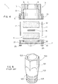
- a silenced nozzle for discharge of extinguishing gases according to the invention denoted as a whole by reference numeral 1, is described with the aid of Figures 1-4.
- the nozzle 1 consists essentially of three elements: a base body 2, a cover 3 and an assembly of sintered filters 4 comprised between the base body 2 and the cover 3.
- the base body 2 and the cover 3 can equally well be made from materials such as aluminium, brass or stainless steel.
- the cover 3 consists of a cylindrical tang 5 with a diameter of about 83 mm terminating in a circular flange 6 with a diameter of about 100 mm.
- An axial hole 7 is formed in the upper surface of the cylindrical tang 5 for entry of the extinguishing gas.
- the hole 7 has a diameter of about 30 mm which is a standard size for attachment to extinguishing gas dispensers.
- An axial hole 8 for propagation of the gas having a slightly smaller diameter than the outer diameter of the cylindrical tang 5, is formed in the lower surface of the flange 6. In this manner the hole 8 can continue inside the cylindrical tang 5 and be in communication with the hole 7 which occupies only an upper part of the tang 5.
- the diameter of the hole 8 is in any case substantially greater than the diameter of the hole 7 for entry of the extinguishing gas.
- Holes 9 are formed in the upper surface of the tang 5 for outlet of the gas.
- the holes 9 are disposed circumferentially around the gas inlet hole 7 and communicate with the hole 8 for propagation of the gas.
- eight holes 9 can be disposed on a circumference and spaced at 45° to one another.
- the diameter of each hole can preferably be about 5 mm.
- the holes 10 are formed in the peripheral part of the flange 6 to receive respective tightening bolts 11.
- the holes 10 are preferably spaced at 90°.
- the base body 2 consists of a cylindrical plate with a diameter of about 100 mm, substantially equal to the diameter of the flange 6 of the cover 3.
- a circular seat 20 having a diameter substantially equal to the diameter of the hole 8 of the cover 3 is formed in the upper surface of the base body 2.
- a plurality of holes 21 (in the example shown seventeen holes with a diameter of about 5 mm) for outlet of the extinguishing gas, communicating with the circular seat 20, are formed in the lower surface of the basic body 2.
- the filter assembly 4 provides two sintered filters 31 and 32, made with zinc-coated metal wires suitably pressed in special moulds so as to obtain disk-shaped filter bodies, with a diameter equal to or slightly smaller than the diameter of the hole 8 of the cover 3.
- the filters 31 and 32 are subjected to diffusion heat treatment, so as to be able to achieve a high mechanical resistance which guarantees a long life even when used at high pressures and high temperatures (about 500 °C).
- the filters 31 and 32 furthermore have a very high filtering field (10-50 microns) in this case to ensure that the noisiness due to the fluctuation of air caused by discharge of extinguishing gas can be considerably attenuated.
- a metal baffle is provided between the two filters 31 and 32 to deflect the flow of extinguishing gas.
- the filter assembly 4 comprising the sintered filters 31 and 32 with the baffle 33 interposed, is housed inside the hole 8 of the cover and the bottom end of the filter 31 is housed in the seat 20 of the base body.
- the bolts 11 engage in the respective holes 10 and 22 and are tightened by means of nuts 25 which are screwed to the end of the shank of each bolt 11 which protrudes downward from the base body 2.
- the height of the filter assembly 4 is designed so that there is a height of at least 20 mm between the lower surface 6 of the flange and upper surface of the base body 2, thus the lateral surface of the filter assembly 4 remains uncovered for a about 20 mm.
- the height of the base body 2 and of the cover 3 is designed so that the total height of the assembled nozzle is about 100 mm.
- the nozzle 1 can be mounted on a an extinguishing gas dispenser of a fire extinguishing system.
- the extinguishing gas leaving the dispenser enters the nozzle 1 through the inlet hole 7, propagates into the hole 8 passing through the filter assembly 4 and exits upward through the outlet holes 9 in the upper surface of the nozzle 1, downward through the outlet holes 21 in the bottom surface of the nozzle and sideward from the lateral surface of the filter assembly 4 which remains uncovered.
- the gas enters the inlet hole 7 which has a sectional area of about 706 mm and is propagated into the hole 8 which has a substantially larger sectional area. This attenuates the pressure of the gas and thus the noise during discharge of gas.
- the particular structure of the nozzle 1 according to the invention provides a larger surface for the formation of gas outlet holes, compared with prior art nozzles.
- the nozzle according to the invention there can be seventeen holes in the lower surface and eight holes in the upper surface, for a total of twenty-five holes.
- the gas has a further outlet area represented by the lateral surface of the filter assembly 4 which remains uncovered.
- the nozzle 200 comprises a base body 202, a cover 203 and a filter assembly 4 substantially identical to that described in the first embodiment.
- the cover 203 comprises a hollow cylindrical body 205 inside which is situated a seat or chamber 208 to contain the filter assembly 4.
- the cylindrical body has rectangular slots 230 communicating with the inner chamber 208.
- Four slots 230 are preferably provided so as to form four columns 231 (three visible in Figure 6) that connect the upper part of the cylindrical body 205 to the lower part thereof.
- the cylindrical body 205 can be produced by fusion connecting an upper cylinder to a lower cylinder by means of the columns 231.
- a glass-shaped mouth 233 that has seat 234 open toward the outside to receive the gas dispensing line is provided on the upper surface of the cylindrical body 205.
- the seat 234 has an aperture 207 communicating with the chamber 208.
- a plurality of axial holes 9 communicating with the chamber 208 is formed in the upper surface of the cylindrical body 205, on the outside with respect to the mouth 233. As in the first embodiment the holes 9 can be eight in number.
- the cylindrical body 205 has an inner thread 240 destined to engage with a respective outer thread 241 provided in the base body 202.
- the base body 202 is a cylindrical plate that has a plurality of axial holes 21, for example seventeen as in the first embodiment.
- the filter assembly 4 it is sufficient to insert the filter assembly 4 in the chamber 208 of the cover 203 and screw the base body 202 into the bottom end of the cover 203.
- the gas dispensing line is housed in the seat 234 of the mouth 233, therefore the gas delivered, through the aperture 207 expands in the chamber 208 and the fluctuation of the air is attenuated by the filters 4.
- the extinguishing gas is discharged upward from the holes 9, sideward from the slots 230 and downward from the holes 21.
Landscapes
- Health & Medical Sciences (AREA)
- Public Health (AREA)
- Business, Economics & Management (AREA)
- Emergency Management (AREA)
- Nozzles (AREA)
Abstract
Description
Claims (13)
- A silenced nozzle (1; 200) for discharge of extinguishing gases comprising a body (2, 3; 202, 203) in which a hole (7; 207) for entry of extinguishing gas and a plurality of holes (9, 21) for discharge of extinguishing gas are formed, characterized in that a filter assembly (4) able to attenuate the noise caused during discharge of the extinguishing gas is provided inside said body.
- A nozzle (1; 200) according to claim 1, characterised in that said body of the nozzle comprises a base body (2; 202) and a cover (3; 303) assembled with one another so as to enclose within them said filter assembly (4).
- A nozzle (1) according to claim 2, characterized in that said cover (3) comprises a cylindrical tang (5) terminating in a circular flange (6) with a greater diameter, to receive securing means (11) for assembly to said basic body (2).
- A nozzle (1; 200) according to claim 2 or 3, characterized in that said cover (3; 203) has an inlet hole (7; 207) for the extinguishing gas, communicating with a hole (8; 208) for propagation of the extinguishing gas, having a greater diameter than the inlet hole, in order to have an attenuation of the pressure of the extinguishing gas during discharge.
- A nozzle (1; 200) according to claim 4, characterized in that in the upper surface of said cover (3; 203) in a peripheral area with respect to said inlet hole (7; 207) for the extinguishing gas, a plurality of outlet holes (9) for the extinguishing gas are provided, communicating with said hole (8; 208) for propagation of the extinguishing gas.
- A nozzle (1; 200) according to claim 4 or 5, characterized in that said filter assembly (4) is housed in said hole (8; 208) for propagation of the extinguishing gas.
- A nozzle (1) according to any one of claims 2 to 6, characterized in that said base body (2) has a seat (20) to receive said filter assembly (4), communicating with a plurality of outlet holes (21) for the extinguishing gas.
- A nozzle (1) according to any one of claims 2 to 7, characterized in that between the lower surface of said cover (6) and the upper surface of said base body (2) a certain space is left so as to leave uncovered at least part of the lateral surface of the filter assembly (4) to allow outflow of the extinguishing gas from the lateral surface of the filter assembly (4).
- A nozzle (200) according to claims 2 to 7, characterized in that said cover (203) is made in a single piece and has side slots (230) communicating with the inside and open toward the outside to allow outflow of the extinguishing gas from the lateral surface of the filter assembly (4).
- A nozzle (1; 200) according to any one of the preceding claims, characterized in that said filter assembly (4) comprises at least one sintered filter (31, 32) made by means of zinc-coated metal wires, suitably pressed to have a high filtration field.
- A nozzle (1; 200) according to claim 10, characterized in that said at least one filter (31, 32) is subjected to a heat diffusion treatment able to give it a greater resistance at high pressures and temperatures.
- A nozzle (1; 200) according to any one of the preceding claims, characterized in that said filter assembly (4) comprises two filters (31, 32) and a baffle (33) interposed between them.
- A silenced nozzle (1; 200) for discharge of extinguishing gases comprising a body (2, 3; 202; 203) in which a hole (7; 207) is formed for entry of the extinguishing gas communicating with a hole (8; 208) for propagation of the extinguishing gas, the hole (8; 208) communicating with a plurality of outlet holes (9, 21) for extinguishing gas, characterized in that said hole (8; 208) for propagation of the extinguishing gas has a greater diameter with respect to the diameter of the inlet hole (7; 207) for the extinguishing gas, in order to attenuate the pressure of the gas during discharge.
Applications Claiming Priority (2)
| Application Number | Priority Date | Filing Date | Title |
|---|---|---|---|
| ITMI000989 | 2000-05-05 | ||
| IT2000MI000989A IT1317475B1 (en) | 2000-05-05 | 2000-05-05 | NOZZLE SILENCED FOR THE DISCHARGE OF EXTINGUISHING GASES. |
Publications (2)
| Publication Number | Publication Date |
|---|---|
| EP1151800A2 true EP1151800A2 (en) | 2001-11-07 |
| EP1151800A3 EP1151800A3 (en) | 2002-09-11 |
Family
ID=11444982
Family Applications (1)
| Application Number | Title | Priority Date | Filing Date |
|---|---|---|---|
| EP00126770A Withdrawn EP1151800A3 (en) | 2000-05-05 | 2000-12-06 | Silenced nozzle for discharge of extinguishing gas |
Country Status (3)
| Country | Link |
|---|---|
| EP (1) | EP1151800A3 (en) |
| IT (1) | IT1317475B1 (en) |
| ZA (1) | ZA200103341B (en) |
Cited By (26)
| Publication number | Priority date | Publication date | Assignee | Title |
|---|---|---|---|---|
| JP2001033983A (en) * | 1999-07-15 | 2001-02-09 | Mitsubishi Electric Corp | Pattern forming method, semiconductor device manufacturing method using the same, and semiconductor device |
| GB2405666A (en) * | 2003-09-05 | 2005-03-09 | Dunlop Aerospace Ltd | Noise attenuator, eg for turbofan engine air bleed system |
| JP2011125673A (en) * | 2009-11-02 | 2011-06-30 | Koatsu Co Ltd | Jet head having silencing function for gas-based fire extinguishing system |
| US20120205128A1 (en) * | 2009-10-23 | 2012-08-16 | Air Water Safety Service Inc. | Gas fire-extinguishing apparatus |
| WO2012154652A1 (en) * | 2011-05-12 | 2012-11-15 | Fike Corporation | Inert gas suppression system nozzle |
| JP2013000195A (en) * | 2011-06-13 | 2013-01-07 | Air Water Safety Service Inc | Nozzle structure |
| WO2012136468A3 (en) * | 2011-04-08 | 2013-05-16 | Siemens Aktiengesellschaft | Reduced-noise extinguishing nozzles |
| JP2013150820A (en) * | 2009-10-23 | 2013-08-08 | Air Water Safety Service Inc | Gas fire extinguishing equipment |
| WO2013125383A1 (en) * | 2012-02-21 | 2013-08-29 | 株式会社コーアツ | Spray head for gaseous fire extinguishing equipment having silencing function |
| JP2013169333A (en) * | 2012-02-21 | 2013-09-02 | Koatsu Co Ltd | Jet head with silencing function for gas type fire extinguishing equipment |
| JP2013169472A (en) * | 2013-04-17 | 2013-09-02 | Koatsu Co Ltd | Jet head with silencing function for gas type fire extinguishing equipment |
| JP2013192764A (en) * | 2012-03-21 | 2013-09-30 | Koatsu Co Ltd | Spray head for gaseous fire extinguishing equipment having silencing function |
| WO2017096249A1 (en) * | 2015-12-04 | 2017-06-08 | Tyco Fire Products Lp | Low pressure drop accoustic suppressor nozzle for fire protection inert gas discharge system |
| WO2017096261A1 (en) * | 2015-12-04 | 2017-06-08 | Tyco Fire Products Lp | Low pressure drop acoustic suppressor nozzle for inert gas discharge system |
| EP3195905A1 (en) * | 2016-01-22 | 2017-07-26 | Extinctium | Silent gas-diffusion nozzle |
| JP2017221683A (en) * | 2013-10-02 | 2017-12-21 | エア・ウォーター防災株式会社 | Fire extinguishing gas injection equipment construction method |
| JP2018057724A (en) * | 2016-10-07 | 2018-04-12 | ニッタン株式会社 | Gas discharge nozzle for gas fire extinguishment facility |
| WO2018123656A1 (en) * | 2016-12-26 | 2018-07-05 | 株式会社コーアツ | Jet head having silencing function for gas-based fire extinguishing equipment, and method for storing and assembling same |
| WO2018212160A1 (en) * | 2017-05-19 | 2018-11-22 | 株式会社コーアツ | Spray head for liquefied fire-extinguishing agent |
| WO2019141819A1 (en) | 2018-01-21 | 2019-07-25 | Luxembourg Patent Company S.A. | Silenced head for fire extinguishing gas discharge |
| WO2020028731A1 (en) * | 2018-08-02 | 2020-02-06 | Carrier Corporation | Low noise nozzle assembly for fire suppression system |
| WO2020071329A1 (en) * | 2018-10-02 | 2020-04-09 | 株式会社コーアツ | Spray head for liquefied fire-extinguishing agent |
| US11117007B2 (en) | 2017-11-10 | 2021-09-14 | Carrier Corporation | Noise reducing fire suppression nozzles |
| RU2786611C2 (en) * | 2018-10-02 | 2022-12-22 | Коацу Ко., Лтд. | Spraying head for liquid extinguishing agent |
| JP2024070458A (en) * | 2022-11-11 | 2024-05-23 | ヤマトプロテック株式会社 | Injection head and gas fire extinguishing equipment including the injection head |
| WO2024257508A1 (en) * | 2023-06-13 | 2024-12-19 | 株式会社コーアツ | Injection head equipped with silencing means for gas-based fire extinguishing equipment |
Family Cites Families (6)
| Publication number | Priority date | Publication date | Assignee | Title |
|---|---|---|---|---|
| US3345878A (en) * | 1964-12-02 | 1967-10-10 | James N Grant | Card assembly sampler |
| US3811622A (en) * | 1972-11-06 | 1974-05-21 | L Blatt | Air blow gun for chip and debris cleaning |
| US3960239A (en) * | 1973-08-15 | 1976-06-01 | Barry Wright Corporation | Noise-reducing fluid-flow devices |
| SE381983B (en) * | 1974-04-05 | 1976-01-12 | Sunne Gummifab Ab | SOUND Muffler BLASZY NOZZLE |
| DE4101668A1 (en) * | 1991-01-22 | 1992-07-23 | Messer Griesheim Gmbh | FIRE EXTINGUISHING DEVICE WITH A STORAGE FOR A LOW-BOILED GAS LIQUIDED |
| NL9401480A (en) * | 1994-09-09 | 1996-04-01 | Tech Inspectie En Adviesbureau | Method for extinguishing a fire. |
-
2000
- 2000-05-05 IT IT2000MI000989A patent/IT1317475B1/en active
- 2000-12-06 EP EP00126770A patent/EP1151800A3/en not_active Withdrawn
-
2001
- 2001-04-24 ZA ZA200103341A patent/ZA200103341B/en unknown
Cited By (82)
| Publication number | Priority date | Publication date | Assignee | Title |
|---|---|---|---|---|
| JP2001033983A (en) * | 1999-07-15 | 2001-02-09 | Mitsubishi Electric Corp | Pattern forming method, semiconductor device manufacturing method using the same, and semiconductor device |
| GB2405666A (en) * | 2003-09-05 | 2005-03-09 | Dunlop Aerospace Ltd | Noise attenuator, eg for turbofan engine air bleed system |
| JP2014144383A (en) * | 2009-10-23 | 2014-08-14 | Air Water Safety Service Inc | Equipment room, gas fire-extinguishing method and gas fire-extinguishing equipment |
| JP2014166592A (en) * | 2009-10-23 | 2014-09-11 | Air Water Safety Service Inc | Fire-extinguishing gas injection device |
| JP2025071321A (en) * | 2009-10-23 | 2025-05-02 | エア・ウォーター防災株式会社 | Fire extinguishing method that reduces O2 concentration |
| JP7591009B2 (en) | 2009-10-23 | 2024-11-27 | エア・ウォーター防災株式会社 | Gas fire extinguishing equipment |
| JP2017209524A (en) * | 2009-10-23 | 2017-11-30 | エア・ウォーター防災株式会社 | Fire extinguishing gas injection device |
| JP2013150820A (en) * | 2009-10-23 | 2013-08-08 | Air Water Safety Service Inc | Gas fire extinguishing equipment |
| JP2023171526A (en) * | 2009-10-23 | 2023-12-01 | エア・ウォーター防災株式会社 | Gas-based fire extinguishing facility |
| JP7344240B2 (en) | 2009-10-23 | 2023-09-13 | エア・ウォーター防災株式会社 | Silencer and gas fire extinguishing equipment |
| JP2014166591A (en) * | 2009-10-23 | 2014-09-11 | Air Water Safety Service Inc | Fire-extinguishing gas injection device |
| JP2021104350A (en) * | 2009-10-23 | 2021-07-26 | エア・ウォーター防災株式会社 | Noise suppressor |
| JP2021037317A (en) * | 2009-10-23 | 2021-03-11 | エア・ウォーター防災株式会社 | Construction method of the injection head and its injection head in the fire extinguishing target section |
| US9457214B2 (en) | 2009-10-23 | 2016-10-04 | Air Water Safety Service Inc. | Gas fire-extinguishing apparatus |
| JP2014097428A (en) * | 2009-10-23 | 2014-05-29 | Air Water Safety Service Inc | Fire-extinguishing gas injection device |
| JP2014128701A (en) * | 2009-10-23 | 2014-07-10 | Air Water Safety Service Inc | Fire-extinguishing gas spraying apparatus |
| US20120205128A1 (en) * | 2009-10-23 | 2012-08-16 | Air Water Safety Service Inc. | Gas fire-extinguishing apparatus |
| JP2017104560A (en) * | 2009-10-23 | 2017-06-15 | エア・ウォーター防災株式会社 | Gas fire-extinguishing equipment |
| JP2022145844A (en) * | 2009-10-23 | 2022-10-04 | エア・ウォーター防災株式会社 | Gas-based fire extinguishing facility |
| CN104014097A (en) * | 2009-10-23 | 2014-09-03 | 爱沃特防灾株式会社 | Gas fire-extinguishing facility |
| JP2016165496A (en) * | 2009-10-23 | 2016-09-15 | エア・ウォーター防災株式会社 | Fire extinguishing gas injection device |
| JP2019202153A (en) * | 2009-10-23 | 2019-11-28 | エア・ウォーター防災株式会社 | Fire-extinguishing gas injection device and gas extinguishment facility using the same, and construction method for fire-extinguishing gas injection device |
| JP2018023846A (en) * | 2009-10-23 | 2018-02-15 | エア・ウォーター防災株式会社 | Gas fire extinguishing equipment |
| JP2015142854A (en) * | 2009-10-23 | 2015-08-06 | エア・ウォーター防災株式会社 | Gas fire-extinguishing facility |
| EP2491984A4 (en) * | 2009-10-23 | 2015-10-07 | Air Water Safety Service Inc | DEVICE FOR EXTINGUISHING FIRE BY MEANS OF A GAS |
| JP2015192875A (en) * | 2009-10-23 | 2015-11-05 | エア・ウォーター防災株式会社 | Equipment room, gas fire-extinguishing method and gas fire-extinguishing equipment |
| JP2015198974A (en) * | 2009-10-23 | 2015-11-12 | エア・ウォーター防災株式会社 | Fire extinguishing gas injection device |
| EP3243552A3 (en) * | 2009-10-23 | 2018-02-21 | Air Water Safety Service Inc. | Gas fire-extinguishing apparatus |
| JP2015006620A (en) * | 2009-11-02 | 2015-01-15 | 株式会社コーアツ | Jet head having silencing function for gas-based fire extinguishing system |
| JP2011125673A (en) * | 2009-11-02 | 2011-06-30 | Koatsu Co Ltd | Jet head having silencing function for gas-based fire extinguishing system |
| JP2014087707A (en) * | 2009-11-02 | 2014-05-15 | Koatsu Co Ltd | Jet head having silencing function for gas-based fire extinguishing system |
| JP2016174940A (en) * | 2009-11-02 | 2016-10-06 | 株式会社コーアツ | Injection head having silencing function for gaseous system fire-extinguishing facility |
| JP2018008128A (en) * | 2009-11-02 | 2018-01-18 | 株式会社コーアツ | Injection head having silencing function for gaseous system fire-extinguishing facility |
| WO2012136468A3 (en) * | 2011-04-08 | 2013-05-16 | Siemens Aktiengesellschaft | Reduced-noise extinguishing nozzles |
| US8887820B2 (en) | 2011-05-12 | 2014-11-18 | Fike Corporation | Inert gas suppression system nozzle |
| WO2012154652A1 (en) * | 2011-05-12 | 2012-11-15 | Fike Corporation | Inert gas suppression system nozzle |
| CN103635234A (en) * | 2011-05-12 | 2014-03-12 | 法克有限公司 | Inert gas suppression system nozzle |
| JP2013000195A (en) * | 2011-06-13 | 2013-01-07 | Air Water Safety Service Inc | Nozzle structure |
| CN104159642A (en) * | 2012-02-21 | 2014-11-19 | 株式会社高压 | Spray head for gaseous fire extinguishing equipment having silencing function |
| TWI566804B (en) * | 2012-02-21 | 2017-01-21 | 高壓股份有限公司 | Spray head with muffling function for gas system fire extinguishing equipment |
| RU2579000C1 (en) * | 2012-02-21 | 2016-03-27 | Коацу Ко., Лтд. | Atomiser with function of noise suppression for gas fire extinguishing system |
| EP2818207A4 (en) * | 2012-02-21 | 2015-11-18 | Koatsu Co Ltd | SPRAY HEAD FOR GAS FIRE EXTINGUISHING SYSTEM HAVING NOISE MITIGATION FUNCTION |
| JP2013169333A (en) * | 2012-02-21 | 2013-09-02 | Koatsu Co Ltd | Jet head with silencing function for gas type fire extinguishing equipment |
| WO2013125383A1 (en) * | 2012-02-21 | 2013-08-29 | 株式会社コーアツ | Spray head for gaseous fire extinguishing equipment having silencing function |
| CN104159642B (en) * | 2012-02-21 | 2017-10-13 | 株式会社高压 | The gas injector head with silencing function used for fire-extinguishing equipment |
| US10258816B2 (en) | 2012-02-21 | 2019-04-16 | Koatsu Co., Ltd. | Injection head having silencing function for gas-type fire extinguisher |
| JP2013192764A (en) * | 2012-03-21 | 2013-09-30 | Koatsu Co Ltd | Spray head for gaseous fire extinguishing equipment having silencing function |
| JP2013169472A (en) * | 2013-04-17 | 2013-09-02 | Koatsu Co Ltd | Jet head with silencing function for gas type fire extinguishing equipment |
| JP2017221683A (en) * | 2013-10-02 | 2017-12-21 | エア・ウォーター防災株式会社 | Fire extinguishing gas injection equipment construction method |
| US11857817B2 (en) | 2015-12-04 | 2024-01-02 | Tyco Fire Products Lp | Low pressure drop acoustic suppressor nozzle for inert gas discharge system |
| WO2017096261A1 (en) * | 2015-12-04 | 2017-06-08 | Tyco Fire Products Lp | Low pressure drop acoustic suppressor nozzle for inert gas discharge system |
| US10507343B2 (en) | 2015-12-04 | 2019-12-17 | Tyco Fire Products Lp | Low pressure drop acoustic suppressor nozzle for fire protection inert gas discharge system |
| US11389678B2 (en) | 2015-12-04 | 2022-07-19 | Tyco Fire Products Lp | Low pressure drop acoustic suppressor nozzle for inert gas discharge system |
| WO2017096249A1 (en) * | 2015-12-04 | 2017-06-08 | Tyco Fire Products Lp | Low pressure drop accoustic suppressor nozzle for fire protection inert gas discharge system |
| US11612773B2 (en) | 2015-12-04 | 2023-03-28 | Tyco Fire Products Lp | Low pressure drop acoustic suppressor nozzle for fire protection inert gas discharge system |
| FR3046943A1 (en) * | 2016-01-22 | 2017-07-28 | Extinctium | SILENT NOZZLE OF GAS DIFFUSION. |
| EP3195905A1 (en) * | 2016-01-22 | 2017-07-26 | Extinctium | Silent gas-diffusion nozzle |
| JP2018057724A (en) * | 2016-10-07 | 2018-04-12 | ニッタン株式会社 | Gas discharge nozzle for gas fire extinguishment facility |
| JP6363318B1 (en) * | 2016-12-26 | 2018-07-25 | 株式会社コーアツ | Ejection head having a silencing function for gas fire extinguishing equipment and method for storing and assembling the same |
| RU2725359C1 (en) * | 2016-12-26 | 2020-07-02 | Коацу Ко., Лтд. | Nozzle with noise absorption function for gas fire extinguishing means and method of storage and assembly thereof |
| WO2018123656A1 (en) * | 2016-12-26 | 2018-07-05 | 株式会社コーアツ | Jet head having silencing function for gas-based fire extinguishing equipment, and method for storing and assembling same |
| JP7031829B2 (en) | 2017-05-19 | 2022-03-08 | 株式会社コーアツ | Injection head for liquefied fire extinguishing agent |
| US11130010B2 (en) | 2017-05-19 | 2021-09-28 | Koatsu Co., Ltd. | Injection head for liquefied fire-extinguishing agent |
| RU2761307C2 (en) * | 2017-05-19 | 2021-12-07 | Коацу Ко., Лтд. | Spray head for liquid extinguishing agent |
| TWI757488B (en) * | 2017-05-19 | 2022-03-11 | 日商高壓股份有限公司 | Injection head for liquefaction fire-extinguishing agents |
| WO2018212160A1 (en) * | 2017-05-19 | 2018-11-22 | 株式会社コーアツ | Spray head for liquefied fire-extinguishing agent |
| JPWO2018212160A1 (en) * | 2017-05-19 | 2020-05-21 | 株式会社コーアツ | Jet head for liquefied fire extinguisher |
| US11931613B2 (en) | 2017-11-10 | 2024-03-19 | Carrier Corporation | Noise reducing fire suppression nozzles |
| US11117007B2 (en) | 2017-11-10 | 2021-09-14 | Carrier Corporation | Noise reducing fire suppression nozzles |
| WO2019141819A1 (en) | 2018-01-21 | 2019-07-25 | Luxembourg Patent Company S.A. | Silenced head for fire extinguishing gas discharge |
| CN112218689A (en) * | 2018-08-02 | 2021-01-12 | 开利公司 | Low Noise Nozzle Assemblies for Fire Extinguishing Systems |
| WO2020028731A1 (en) * | 2018-08-02 | 2020-02-06 | Carrier Corporation | Low noise nozzle assembly for fire suppression system |
| CN112312975A (en) * | 2018-10-02 | 2021-02-02 | 株式会社高压 | Nozzle for liquefied fire extinguishing agent |
| JP7299629B2 (en) | 2018-10-02 | 2023-06-28 | 株式会社コーアツ | Injection head for liquefied extinguishing agent |
| TWI799647B (en) * | 2018-10-02 | 2023-04-21 | 日商高壓股份有限公司 | Nozzles for liquid fire extinguishing agents |
| RU2786611C2 (en) * | 2018-10-02 | 2022-12-22 | Коацу Ко., Лтд. | Spraying head for liquid extinguishing agent |
| CN112312975B (en) * | 2018-10-02 | 2022-10-18 | 株式会社高压 | Spray head for liquefied fire extinguishing agent |
| JPWO2020071329A1 (en) * | 2018-10-02 | 2021-09-16 | 株式会社コーアツ | Injection head for liquefied fire extinguisher |
| WO2020071329A1 (en) * | 2018-10-02 | 2020-04-09 | 株式会社コーアツ | Spray head for liquefied fire-extinguishing agent |
| JP2024070458A (en) * | 2022-11-11 | 2024-05-23 | ヤマトプロテック株式会社 | Injection head and gas fire extinguishing equipment including the injection head |
| WO2024257508A1 (en) * | 2023-06-13 | 2024-12-19 | 株式会社コーアツ | Injection head equipped with silencing means for gas-based fire extinguishing equipment |
| JP7669013B1 (en) * | 2023-06-13 | 2025-04-28 | 株式会社コーアツ | Jet head with sound dampening means for gas-based fire extinguishing equipment |
Also Published As
| Publication number | Publication date |
|---|---|
| ITMI20000989A0 (en) | 2000-05-05 |
| IT1317475B1 (en) | 2003-07-09 |
| ZA200103341B (en) | 2001-10-26 |
| EP1151800A3 (en) | 2002-09-11 |
| ITMI20000989A1 (en) | 2001-11-05 |
Similar Documents
| Publication | Publication Date | Title |
|---|---|---|
| ITMI20000989A1 (en) | NOZZLE SILENCED FOR THE DISCHARGE OF EXTINGUISHING GASES. | |
| US6394366B1 (en) | Spray nozzle assembly | |
| EP1828655B1 (en) | Dome check valve | |
| US6505646B1 (en) | Pressure reduction valve for a compressible fluid | |
| EP2869936B1 (en) | Sprinkler system | |
| US8430131B2 (en) | Noise control via outlet jet frequency dispersal | |
| EP3815752B1 (en) | Injection head for liquid fire extinguishing agent | |
| US20030221906A1 (en) | Low-noise pressure reduction system | |
| ES2277965T3 (en) | FLAME LOCK PROVISION. | |
| GB2056563A (en) | Pneumatic exhaust | |
| US5647438A (en) | Explosion suppressant dispersion nozzle | |
| JP4542110B2 (en) | Trap device for preventing flame jet of internal combustion engine | |
| US4705138A (en) | Steam trap muffler | |
| EP3714947B1 (en) | Nozzle and valve assembly for a fire extinguisher | |
| EP1964600B1 (en) | Filter cartridge with inlet flow diffuser | |
| KR100231753B1 (en) | Fluid flow filter and method of making same | |
| US5928510A (en) | Filter apparatus for even flow distribution | |
| CN112218689A (en) | Low Noise Nozzle Assemblies for Fire Extinguishing Systems | |
| US5490929A (en) | Cleaner for atomizer | |
| WO1999042181A1 (en) | Fire-extinguisher nozzle | |
| US7686330B2 (en) | Gas generator | |
| EP3740290B1 (en) | Silenced head for fire extinguishing gas discharge | |
| WO2016096598A1 (en) | Burner apparatus and method for optimizing a burner apparatus | |
| JP7842450B2 (en) | Filter device | |
| EP3554649A1 (en) | Flame arrester block for protection devices against the propagation of flames |
Legal Events
| Date | Code | Title | Description |
|---|---|---|---|
| PUAI | Public reference made under article 153(3) epc to a published international application that has entered the european phase |
Free format text: ORIGINAL CODE: 0009012 |
|
| AK | Designated contracting states |
Kind code of ref document: A2 Designated state(s): AT BE CH CY DE DK ES FI FR GB GR IE IT LI LU MC NL PT SE TR |
|
| AX | Request for extension of the european patent |
Free format text: AL;LT;LV;MK;RO;SI |
|
| PUAL | Search report despatched |
Free format text: ORIGINAL CODE: 0009013 |
|
| AK | Designated contracting states |
Kind code of ref document: A3 Designated state(s): AT BE CH CY DE DK ES FI FR GB GR IE IT LI LU MC NL PT SE TR |
|
| AX | Request for extension of the european patent |
Free format text: AL;LT;LV;MK;RO;SI |
|
| 17P | Request for examination filed |
Effective date: 20030204 |
|
| AKX | Designation fees paid |
Designated state(s): AT BE CH CY DE DK ES FI FR GB GR IE IT LI LU MC NL PT SE TR |
|
| RAP1 | Party data changed (applicant data changed or rights of an application transferred) |
Owner name: GASTEC-VESTA S.R.L. |
|
| GRAP | Despatch of communication of intention to grant a patent |
Free format text: ORIGINAL CODE: EPIDOSNIGR1 |
|
| STAA | Information on the status of an ep patent application or granted ep patent |
Free format text: STATUS: THE APPLICATION IS DEEMED TO BE WITHDRAWN |
|
| 18D | Application deemed to be withdrawn |
Effective date: 20080410 |