EP1150593B1 - Dynamische sitzvorrichtung - Google Patents
Dynamische sitzvorrichtung Download PDFInfo
- Publication number
- EP1150593B1 EP1150593B1 EP00906272A EP00906272A EP1150593B1 EP 1150593 B1 EP1150593 B1 EP 1150593B1 EP 00906272 A EP00906272 A EP 00906272A EP 00906272 A EP00906272 A EP 00906272A EP 1150593 B1 EP1150593 B1 EP 1150593B1
- Authority
- EP
- European Patent Office
- Prior art keywords
- seat component
- supporting element
- seat
- bearing
- swivelling
- Prior art date
- Legal status (The legal status is an assumption and is not a legal conclusion. Google has not performed a legal analysis and makes no representation as to the accuracy of the status listed.)
- Expired - Lifetime
Links
Images




Classifications
-
- A—HUMAN NECESSITIES
- A47—FURNITURE; DOMESTIC ARTICLES OR APPLIANCES; COFFEE MILLS; SPICE MILLS; SUCTION CLEANERS IN GENERAL
- A47C—CHAIRS; SOFAS; BEDS
- A47C3/00—Chairs characterised by structural features; Chairs or stools with rotatable or vertically-adjustable seats
- A47C3/02—Rocking chairs
- A47C3/025—Rocking chairs with seat, or seat and back-rest unit, elastically mounted in a rigid frame
- A47C3/0255—Rocking chairs with seat, or seat and back-rest unit, elastically mounted in a rigid frame pivotally mounted in the base frame, e.g. swings
-
- A—HUMAN NECESSITIES
- A47—FURNITURE; DOMESTIC ARTICLES OR APPLIANCES; COFFEE MILLS; SPICE MILLS; SUCTION CLEANERS IN GENERAL
- A47C—CHAIRS; SOFAS; BEDS
- A47C9/00—Stools for specified purposes
- A47C9/002—Stools for specified purposes with exercising means or having special therapeutic or ergonomic effects
Definitions
- the present invention relates to a dynamic seat device according to the preamble of claim 1 as they is known for example from DE 42 10 134 A1.
- Such a device has the purpose of the sitting process on a known static seating device, such as a chair with a fixed seat and thus disadvantages of immobile, passive sitting for Overcoming a user's back muscles and intervertebral discs. More specifically, is known by a dynamic Seat device in which the seat part as the actual Seat can be moved relative to the underlying support element is kept, the user constantly makes slight movements to maintain a current equilibrium position is forced, with the result that - in orthopedically favorable way - back muscles and intervertebral discs be kept in motion.
- a generic, dynamic seating aid brings again numerous detail problems, which in practical use, for example with large swings in the tilting movement and / or equally large tilting possibilities in and against the direction of the seat, are uncomfortable and cause that the user quickly takes a so-called comfort position, which makes it easier for him to balance, but again at the same time is anatomically questionable.
- EP-A-0 574 375 discloses a dynamic seating device known with the features of the preamble of the main claim. However, this is one in terms of device limited to its adjustability.
- a preferably large, i.e. over a large part of the seat or Buffer element made of foam, Rubber, horsehair or the like elastic material that meets your needs
- suitable bearing elements can also be rod-shaped Bearing elements, a plurality adjacent along an axis arranged individual bearing elements or the like. used are about a pivot between focal axes To determine support element and seat part.
- the elastic buffer element has a greater thickness has as the height of an inserted bearing element, such as a rod, allows such an arrangement next to a pivoting around those defined by the rod Axis, additional slight tilting or swiveling movements along the axis (and thus around a second, vertical Swivel axis with reduced swivel stroke) - a constructive Advantage that turns out to be particularly in practice orthopedic effective improvement of a traditional, only proven seat pivotable about a fixed axis Has.
- Another - mechanical - advantage of the invention Providing a second pivot axis with different (here: reduced) maximum swivel stroke (i.e. maximum swivel angle) is the low susceptibility to Vibration breaks or the like Material failure with frequent, impulsive load, for example by heavy users.
- a current To fix the swivel position by means of suitable locks as well as, for example, by inserting additional ones Spring or damping elements, individual weights and the desire for softer or tighter elastic Behavior of the arrangement to be taken into account.
- a special Field of application of such a damping element is Dampening a forward pivot to one to avoid rapid tilting of the pelvis in the sitting direction.
- the present Invention provides the seat part relative to the support element, in particular with respect to the direction of the seat to design, the seat part different, predetermined Corresponding relative positions can take.
- These measures can be different Leverage ratios related to the seat part, combined with corresponding orthopedic effects, reach, for example by moving the seat part in the direction of the seat to the front (in a rear click position of the Swivel axis) to increase the tendency of the seat part, in Tilt the seat direction forward. By such a measure will tilt the user's pelvis forward favors what an erection of the entire upper body has the consequence.
- the present invention can be accomplished in a variety of ways integrate into existing seating, for example by Placing or fastening on static seats; alternative it is possible, the seat device according to the invention itself to be provided directly with feet or a frame, so that it itself becomes a chair. Depending on the application it can also be useful to Direction to an underlying beam or a fixed one Surface) to provide additional damping or elastic means.
- the dynamic seating device a base plate 10 made of a solid material, such as wood, on the top with an elastic pillow layer 12, for example made of foam rubber or the like. formed and with coated, not shown, is provided.
- an elastic pillow layer 12 for example made of foam rubber or the like. formed and with coated, not shown.
- seat direction On User takes a seat on the cushion layer 12, whereby its Direction of view (hereinafter also referred to as seat direction) with the arrow 14 in Fig. 1 (equally but also applies to all other side views).
- a foam rubber elastic buffer block 16 attached, which in turn via an adhesive layer 18 (slip protection) to an underlying one Platen 20 rests.
- an adhesive layer 18 slip protection
- a rod-shaped bearing element 24 embedded with circular or oval cross-section, whereby, as can be seen in Fig. 1 and Fig. 4, the bearing element 24 made of pressure-resistant material (e.g. plastic or Wood) both in the lateral direction (i.e. on both sides of End faces of the bearing element 24), as well as in view to a height of the buffer block 16 (vertical direction of the Fig. 1) surrounded by the foam material of the buffer block 16 is.
- the Bearing element 24 in a (not shown in more detail) Section of the buffer block 16 is inserted and is thus in the position shown in Fig. 1 and Fig. 4 held.
- the base plate 10 about the pivot axis determined by the bearing element 24 is pivotable, depending on the elasticity of the buffer block 16 and that according to the geometry of the arrangement Fig. 1 determined maximum swivel angle (which is typically is around 15 °).
- the maximum Swivel angle additionally by a schematically shown preferably adjustable in at least one position Locking element 26, for example in the form of a cross bar, limited (or brakes) so that the user comfort increases and a possible risk of accident due to a too large Swivel angle to the rear can be reduced.
- additional 1 to 3 show corresponding cross bars (alternatively: foam elements or the like) as handle protection 28 im, based on the seat direction 14, front and rear area to prevent accidental intervention Prevent user's hands and jamming or buffer.
- the support plate 20 (which can alternatively also be omitted), the grip protection elements and / or the holding strip / s 22 can with suitable (not shown in the figures) Fixing agents, such as openings for screw connections or the like, on an underlying stand or Carrying unit, especially on a chair surface, be attached so that conventional, non-dynamic Seating furniture by the present invention easily and with lowest set-up effort with the advantageous usability the present dynamic seat device can be.
- Fixing agents such as openings for screw connections or the like
- an underlying stand or Carrying unit especially on a chair surface
- elastic - adhesive or anti-slip layer 18 on a just put the underlying surface, whereby by whose adhesive effect is already determined accordingly Arrangement can be made.
- FIG. 4 to 9 show the schematic bottom view (i.e. viewed from the bottom of the base plate 10) various Possibilities to realize the bearing element 24: So it is possible to use the axis-shaped shown in Fig. 1 and Fig. 4 Configuration by two or more along one Axial, spherical, cuboid or block-shaped bearing elements 30, 32 to replace, being, according to a preferred Further development of the invention, simply by providing a central bearing element 30, 32 in the in Fig. 7 and Fig. 8 shown the pivotability of the invention Arrangement around only one axis (in particular a transverse axis to the seat direction, as shown in Fig. 1 or Fig.
- the variant shown in Fig. 2 illustrates the cuboid shape in the side view a bearing element 30, as in the configuration 5 and Fig. 7 is used.
- a particular embodiment of the present invention 9 shows: No separate bearing element is provided here, and the storage according to the invention is by the Buffer block 16 (which, in this respect, also has the function of Bearing element takes over) guaranteed.
- the Buffer block 16 which, in this respect, also has the function of Bearing element takes over
- pivoting is not fixed on one axis, but instead the pivoting or tilting of the base plate 10 relative to the support plate 20 or to the holding strips 22 takes place in any, by the buffer block 16 and its elasticity certain way with one on the seat direction 14 set main movement axis.
- a fixed Blocking element 26 limits a maximum swivel stroke
- a fixed Blocking element 26 limits a maximum swivel stroke
- Elements, especially manually in the between base plate 10 and platen 20 defined interior 34 to Varying the locking angle is slidably mounted, provided be, or it can be on the base plate 10 and / or the Platen 20 and / or a retaining strip 22, preferred in the rear area in relation to the seat direction 14, a retractable, retractable or pivotable locking arrangement (not shown) can be provided by a user in the If necessary, is introduced into the interior 34 such that thereby the maximum swivel stroke can be effectively limited.
- such is also Lifting or locking arrangement with an adjustment mechanism provided that the user setting a maximum Locking angle of pivotability allows.
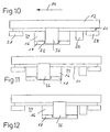
- the buffer block on both sides 16 includes and with its closed middle part runs between the legs above the base plate 10, so that the bracket unit 36 with the buffer block attached 16 and a pair of retaining strips 22 on both sides between a position advanced in the seat direction (FIG. 11) and a rearward position in the seat direction (FIG. 12) can be moved.
- the displacement mechanism 3, 10 to 12 effective locking or fixing unit for example, by fixing the bracket unit 36 (alternatively: belt unit or the like) on the Base plate 10 at predetermined relative displacement positions, locking or secured fixing one set in the desired way by moving it Use position allows.
- Locking or fixing device for this purpose shows a further embodiment of Figures 13 to 18:
- the buffer block 16 encloses a pair bearing blocks 38 arranged on both sides, each to cooperate with a 40 provided with locking grooves Brackets 42 are formed on the base plate 10:
- Fig. 14 front locking position
- Fig. 14 rear locking position
- FIG. 17 shows the arrangement in the schematic bottom view the latching arrangement embedded in the buffer block 16 from bearing blocks 38 and brackets 42, and Fig. 15; 16 clarify a slightly modified variant: Here is the Buffer block 16 based on that defined by the pivot axis Direction shortened so that the arrangement from the bearing block 38 and bracket 42 laterally outside the buffer block 16 lies.
- the present invention is not limited to the embodiments shown limited; so it is particularly in the frame of the present invention, features of the embodiments shown to combine in any way and so too Realization forms of the invention to arrive, depending on the need the suitable one for a particular application Establish configuration.
- buffer block 16 which, alternatively to the described forms of realization made of foam, too from other suitable elastic natural or synthetic materials, such as latex, horsehair or the like. be made can) in its buffering effect by additional spring or To add buffer elements (not shown in the figures) or support: So it is particularly preferred that the Buffer block in or against the seat direction 14 adjacent Position an additional buffer element in the form of a Coil spring, a block of elastic material or the like. assign, and more preferably such an element, which in particular is also regarded as a damping element can be in terms of its damping or To make the buffer effect adjustable, as is the case with Spiral springs or the like by adjusting the spring travel. respectively can.
- the pillow layer (appropriately sourced) 12 with a further edition, shown approximately as an overlay 46 in Fig. 3, so as to choose one suitable material for this overlay, e.g. stable Foam material, an additional adjustment to to reach a user or his body weight.
- one suitable material for this overlay e.g. stable Foam material
- a maximum swivel stroke means which is an instantaneous pivoting position of the arrangement fix, e.g. by attacking from the rear or from the side Bracket, lever, locking or plug-in arrangements, so that a Users on request any dynamic mobility of his Prevent the seat surface relative to the underlying support (detachable) can.
- the present invention can Maximum variability in implementing the advantages of a practical, easy to manufacture dynamic seating device can be achieved.
Landscapes
- Chair Legs, Seat Parts, And Backrests (AREA)
- Seats For Vehicles (AREA)
- Chairs Characterized By Structure (AREA)
- Vibration Prevention Devices (AREA)
- Support Of The Bearing (AREA)
Description
- Fig. 1:
- eine schematische Seitenansicht der dynamischen Sitzvorrichtung;
- Fig. 2:
- eine Variante zur Fig. 1;
- Fig. 3:
- eine schematische Seitenansicht der dynamischen Sitzvorrichtung mit Relativverschiebung;
- Fig. 4 bis Fig. 9:
- verschiedene Realisierungsformen (Varianten) des Lagerelements zur Verwendung in der dynamischen Sitzvorrichtung der vorliegenden Erfindung;
- Fig. 10 bis Fig. 12:
- verschiedene Verschiebepositionen der dynamischen Sitzvorrichtung der Fig. 3;
- Fig. 13, Fig.14:
- schematische Seitenansichten der dynamischen Sitzvorrichtung gemäß einer weiteren Ausführungsform;
- Fig. 15 bis Fig. 18:
- Unteransichten bzw. schematische Seitenansichten der dynamischen Sitzvorrichtung gemäß der dritten Ausführungsform.
Claims (10)
- Dynamische Sitzvorrichtung mit einem relativ zu einem Auflageelement (20; 22) durch Verschwenken um eine erste Schwenkachse mit einem ersten maximalen Schwenkhub bewegbaren Sitzteil (10, 12), wobei mindestens ein Lagerelement (24; 30, 32) zum Definieren eines Lagers zwischen dem Auflageelement und dem Sitzteil mit der ersten Schwenkachse vorgesehen ist, wobei das Lagerelement durch ein das Lagerelement zumindest teilweise umgebendes, das Sitzteil sowie das Auflageelement verbindendes und eine Federkraft für das Lager anbietendes elastisches Pufferelement (16) zwischen Sitzteil und Auflageelement gehalten wird,
wobei das Pufferelement so ausgebildet ist, dass durch das Lager ein Verschwenken um eine zweite, von der ersten Schwenkachse verschiedene Schwenkachse mit einem zweiten, vom ersten Schwenkhub verschiedenen maximalen Schwenkhub, sowie ein Verschwenken lediglich um die erste Schwenkachse ermöglicht ist,
dadurch gekennzeichnet, dass
Mittel (36, 38, 42) zum einstellbaren Verschieben des Sitzteils relativ zum Auflageelement in einer durch das Sitzteil oder das Auflageelement definierten Verschiebungsebene vorgesehen sind. - Vorrichtung nach Anspruch 1, dadurch gekennzeichnet, dass das Pufferelement scheiben-, streifen-, quader- oder kissenförmig od.dgl. realisiert, mit einer Seite mit dem Sitzteil und/oder Auflageelement befestigt und so ausgebildet ist, dass das Lagerelement in das Pufferelement zumindest abschnittsweise eingebettet ist.
- Vorrichtung nach Anspruch 1 oder 2, dadurch gekennzeichnet, dass das elastische Pufferelement aus Schaumgummi, Moosgummi, Latex oder einem anderen elastischen Kunst- oder Naturstoff gebildet ist und zum Aufnehmen des Lagerelements einen Ein- oder Ausschnitt aufweist.
- Vorrichtung nach einem der Ansprüche 1 bis 3, dadurch gekennzeichnet, dass das Lagerelement eine Kugel (32), ein Stab (24) oder ein Quader (30) od.dgl. aus einem bezogen auf eine Sitzbelastung unelastischen oder elastischen Material ist, oder durch das Pufferelement selbst realisiert ist.
- Vorrichtung nach einem der Ansprüche 1 bis 4, dadurch gekennzeichnet, dass eine wirksame Höhe des Lagerelements zwischen Sitzteil und Auflageelement geringer ist als eine Dicke des elastischen Pufferelements.
- Vorrichtung nach einem der Ansprüche 1 bis 5, gekennzeichnet durch in einen Zwischenraum (34) zwischen Sitzteil und Auflageelement durch einen Bediener manuell einbringbare Mittel zum Begrenzen einer Maximalverschwenkung zwischen Sitzteil und Auflageelement, insbesondere in Form einer einsetz- oder einschwenkbaren, weiter bevorzugt höhenverstellbaren Hebel- oder Schraubeinrichtung.
- Vorrichtung nach einem der Ansprüche 1 bis 6, gekennzeichnet durch in einen Zwischenraum (34) zwischen Sitzteil und Auflageelement außerhalb des Pufferelements vorgesehene, bevorzugt in ihrer Kraftwirkung einstellbare Dämpfungsmittel, insbesondere in Form eines verstellbaren Federelements.
- Vorrichtung nach einem der Ansprüche 1 bis 7, gekennzeichnet durch in einen Zwischenraum (34) zwischen Sitzteil und Auflageelement manuell einbringbare oder seitlich oder rückwärtig am Sitzteil und/oder Auflageelement manuell befestigbare Arretierungsmittel zum Fixieren einer Schwenkposition zwischen Sitzteil und Auflageelement.
- Vorrichtung nach einem der Ansprüche 1 bis 8, dadurch gekennzeichnet, dass die Mittel zum Verschieben des Sitzteils Fixier- und/oder Rastmittel (38, 40, 42, 44) zum Herstellen mindestens einer festen Relativposition zwischen Sitzteil und Auflageelement aufweisen, wobei bevorzugt die Verschiebemittel eine Bügel- und/oder Gurtanordnung (36) zum Verbinden von Sitzteil und Auflageelement aufweisen, die das Verschieben entlang einer Richtung, insbesondere der Sitzrichtung (14), gestattet.
- Vorrichtung nach einem der Ansprüche 1 bis 9, dadurch gekennzeichnet, dass an einer dem Sitzteil abgewandten Seite des Auflageelements dieses mit einer Folie, einer elastischen Schicht (16) und/oder einer Fußanordnung versehen ist, und/oder Mittel zur Befestigung auf einem Sitzmöbel aufweist.
Applications Claiming Priority (7)
| Application Number | Priority Date | Filing Date | Title |
|---|---|---|---|
| DE29901774U | 1999-02-02 | ||
| DE29901774U DE29901774U1 (de) | 1999-02-02 | 1999-02-02 | Sitzvorrichtung zur Auflage auf einem Sitzmöbel |
| DE1999117414 DE19917414A1 (de) | 1999-04-17 | 1999-04-17 | Sitzvorrichtung |
| DE19917414 | 1999-04-17 | ||
| DE19933364 | 1999-07-19 | ||
| DE19933364 | 1999-07-19 | ||
| PCT/EP2000/000843 WO2000045675A2 (de) | 1999-02-02 | 2000-02-02 | Dynamische sitzvorrichtung |
Publications (2)
| Publication Number | Publication Date |
|---|---|
| EP1150593A2 EP1150593A2 (de) | 2001-11-07 |
| EP1150593B1 true EP1150593B1 (de) | 2004-04-14 |
Family
ID=27219097
Family Applications (1)
| Application Number | Title | Priority Date | Filing Date |
|---|---|---|---|
| EP00906272A Expired - Lifetime EP1150593B1 (de) | 1999-02-02 | 2000-02-02 | Dynamische sitzvorrichtung |
Country Status (5)
| Country | Link |
|---|---|
| EP (1) | EP1150593B1 (de) |
| AT (1) | ATE264077T1 (de) |
| CA (1) | CA2361274C (de) |
| DE (2) | DE20001678U1 (de) |
| WO (1) | WO2000045675A2 (de) |
Cited By (1)
| Publication number | Priority date | Publication date | Assignee | Title |
|---|---|---|---|---|
| DE202011003055U1 (de) | 2011-02-22 | 2011-05-12 | Keller, Oliver | Dynamische Sitzvorrichtung |
Families Citing this family (1)
| Publication number | Priority date | Publication date | Assignee | Title |
|---|---|---|---|---|
| DE10050249A1 (de) * | 2000-10-11 | 2002-04-25 | Klaus Dieter Voss | Sitzvorrichtung zur Auflage auf einem Sitzmöbel |
Family Cites Families (6)
| Publication number | Priority date | Publication date | Assignee | Title |
|---|---|---|---|---|
| US5035466A (en) * | 1989-04-03 | 1991-07-30 | Krueger International, Inc. | Ergonomic chair |
| US5024485A (en) * | 1990-07-05 | 1991-06-18 | Berg Joseph A | Front and back adjustable rocking seat support arrangement for seat having relatively adjustable sections |
| DE4210134C2 (de) | 1992-03-27 | 1996-02-08 | Josef Gloeckl | Aktivdynamische Sitzvorrichtung |
| AT398160B (de) * | 1992-06-10 | 1994-10-25 | Froschauer Hedwig | Arbeitssessel, insbesondere bürosessel |
| GB2281197A (en) * | 1993-07-24 | 1995-03-01 | Seminar Components | A reclining chair mechanism |
| US5769492A (en) * | 1996-12-10 | 1998-06-23 | Jensen; Robert J. | Back saver sport seat |
-
2000
- 2000-02-02 DE DE20001678U patent/DE20001678U1/de not_active Expired - Lifetime
- 2000-02-02 DE DE50006068T patent/DE50006068D1/de not_active Expired - Lifetime
- 2000-02-02 AT AT00906272T patent/ATE264077T1/de active
- 2000-02-02 CA CA2361274A patent/CA2361274C/en not_active Expired - Fee Related
- 2000-02-02 EP EP00906272A patent/EP1150593B1/de not_active Expired - Lifetime
- 2000-02-02 WO PCT/EP2000/000843 patent/WO2000045675A2/de not_active Ceased
Cited By (1)
| Publication number | Priority date | Publication date | Assignee | Title |
|---|---|---|---|---|
| DE202011003055U1 (de) | 2011-02-22 | 2011-05-12 | Keller, Oliver | Dynamische Sitzvorrichtung |
Also Published As
| Publication number | Publication date |
|---|---|
| CA2361274A1 (en) | 2000-08-10 |
| WO2000045675A2 (de) | 2000-08-10 |
| WO2000045675A3 (de) | 2001-03-29 |
| DE50006068D1 (de) | 2004-05-19 |
| CA2361274C (en) | 2010-09-28 |
| EP1150593A2 (de) | 2001-11-07 |
| ATE264077T1 (de) | 2004-04-15 |
| DE20001678U1 (de) | 2000-07-06 |
Similar Documents
| Publication | Publication Date | Title |
|---|---|---|
| DE19823632C1 (de) | Stuhl, insbesondere Bürostuhl | |
| EP2040582B1 (de) | Rückenlehne für den Sitz eines Stuhls oder Sessels und mit einer derartigen Rückenlehne ausgerüstetes Sitzmöbel | |
| WO1993019647A1 (de) | Aktivdynamische sitzvorrichtung | |
| DE4326609C2 (de) | Bürodrehstuhl | |
| DE10148745B4 (de) | Ein mit Rollen versehenes Untergestell für einen Stuhl | |
| DE4210099A1 (de) | Aktivdynamische Sitzvorrichtung | |
| DE4018436A1 (de) | Aufhaengung zum verbinden von sitz und rueckenlehne eines stuhles mit dessen untergestell | |
| DE4210097A1 (de) | Aktivdynamische Sitzvorrichtung | |
| DE4210134A1 (de) | Aktivdynamische Sitzvorrichtung | |
| DE69508135T2 (de) | Ruhestuhl | |
| EP0574375A1 (de) | Arbeitssessel, insbesondere Bürosessel | |
| DE2000172C3 (de) | Stuhl, insbesondere Arbeitsstuhl | |
| DE9421950U1 (de) | Sitzmöbel | |
| DE7239551U (de) | Sitzmöbel, insbesondere Bürostuhl | |
| EP1150593A2 (de) | Dynamische sitzvorrichtung | |
| DE202016008740U1 (de) | Sitzvorrichtung | |
| DE69507725T2 (de) | Stuhl mit einem unterstütztem Lenkgetriebe | |
| AT411006B (de) | Sitzvorrichtung zur auflage auf einem sitzmöbel | |
| DE102005018194B4 (de) | Sitz-und/oder Liegemöbel, insbesondere Polstersitzmöbel | |
| DE202017006753U1 (de) | Sitzmöbel | |
| DE29800216U1 (de) | Verstellbare Liege | |
| WO2001078558A1 (de) | Sitzmöbel, insbesondere bürostuhl | |
| DE202011003055U1 (de) | Dynamische Sitzvorrichtung | |
| DE2314717C3 (de) | Sitzvorrichtung | |
| DE102012219157A1 (de) | Sitzmöbel, insbesondere Bürodrehstuhl |
Legal Events
| Date | Code | Title | Description |
|---|---|---|---|
| PUAI | Public reference made under article 153(3) epc to a published international application that has entered the european phase |
Free format text: ORIGINAL CODE: 0009012 |
|
| 17P | Request for examination filed |
Effective date: 20010829 |
|
| AK | Designated contracting states |
Kind code of ref document: A2 Designated state(s): AT BE CH CY DE DK ES FI FR GB GR IE IT LI LU MC NL PT SE |
|
| 17Q | First examination report despatched |
Effective date: 20030102 |
|
| GRAH | Despatch of communication of intention to grant a patent |
Free format text: ORIGINAL CODE: EPIDOS IGRA |
|
| GRAS | Grant fee paid |
Free format text: ORIGINAL CODE: EPIDOSNIGR3 |
|
| GRAA | (expected) grant |
Free format text: ORIGINAL CODE: 0009210 |
|
| AK | Designated contracting states |
Kind code of ref document: B1 Designated state(s): AT BE CH DE ES FR GB IT LI NL SE |
|
| PG25 | Lapsed in a contracting state [announced via postgrant information from national office to epo] |
Ref country code: NL Free format text: LAPSE BECAUSE OF FAILURE TO SUBMIT A TRANSLATION OF THE DESCRIPTION OR TO PAY THE FEE WITHIN THE PRESCRIBED TIME-LIMIT Effective date: 20040414 Ref country code: GB Free format text: LAPSE BECAUSE OF FAILURE TO SUBMIT A TRANSLATION OF THE DESCRIPTION OR TO PAY THE FEE WITHIN THE PRESCRIBED TIME-LIMIT Effective date: 20040414 Ref country code: FR Free format text: LAPSE BECAUSE OF FAILURE TO SUBMIT A TRANSLATION OF THE DESCRIPTION OR TO PAY THE FEE WITHIN THE PRESCRIBED TIME-LIMIT Effective date: 20040414 |
|
| REG | Reference to a national code |
Ref country code: GB Ref legal event code: FG4D Free format text: NOT ENGLISH |
|
| REG | Reference to a national code |
Ref country code: CH Ref legal event code: EP |
|
| REF | Corresponds to: |
Ref document number: 50006068 Country of ref document: DE Date of ref document: 20040519 Kind code of ref document: P |
|
| REG | Reference to a national code |
Ref country code: IE Ref legal event code: FG4D Free format text: GERMAN |
|
| PG25 | Lapsed in a contracting state [announced via postgrant information from national office to epo] |
Ref country code: SE Free format text: LAPSE BECAUSE OF FAILURE TO SUBMIT A TRANSLATION OF THE DESCRIPTION OR TO PAY THE FEE WITHIN THE PRESCRIBED TIME-LIMIT Effective date: 20040714 |
|
| PG25 | Lapsed in a contracting state [announced via postgrant information from national office to epo] |
Ref country code: ES Free format text: LAPSE BECAUSE OF FAILURE TO SUBMIT A TRANSLATION OF THE DESCRIPTION OR TO PAY THE FEE WITHIN THE PRESCRIBED TIME-LIMIT Effective date: 20040725 |
|
| REG | Reference to a national code |
Ref country code: CH Ref legal event code: NV Representative=s name: HIEBSCH & PEEGE AG PATENTANWAELTE |
|
| NLV1 | Nl: lapsed or annulled due to failure to fulfill the requirements of art. 29p and 29m of the patents act | ||
| GBV | Gb: ep patent (uk) treated as always having been void in accordance with gb section 77(7)/1977 [no translation filed] |
Effective date: 20040414 |
|
| REG | Reference to a national code |
Ref country code: IE Ref legal event code: FD4D |
|
| PLBE | No opposition filed within time limit |
Free format text: ORIGINAL CODE: 0009261 |
|
| STAA | Information on the status of an ep patent application or granted ep patent |
Free format text: STATUS: NO OPPOSITION FILED WITHIN TIME LIMIT |
|
| PG25 | Lapsed in a contracting state [announced via postgrant information from national office to epo] |
Ref country code: BE Free format text: LAPSE BECAUSE OF NON-PAYMENT OF DUE FEES Effective date: 20050228 |
|
| EN | Fr: translation not filed | ||
| 26N | No opposition filed |
Effective date: 20050117 |
|
| BERE | Be: lapsed |
Owner name: *KELLER OLIVER Effective date: 20050228 |
|
| BERE | Be: lapsed |
Owner name: *KELLER OLIVER Effective date: 20050228 |
|
| REG | Reference to a national code |
Ref country code: CH Ref legal event code: PFA Owner name: KELLER, OLIVER Free format text: KELLER, OLIVER#ROSGARTENSTRASSE 29/31#78462 KONSTANZ (DE) -TRANSFER TO- KELLER, OLIVER#ROSGARTENSTRASSE 29/31#78462 KONSTANZ (DE) |
|
| REG | Reference to a national code |
Ref country code: CH Ref legal event code: NV Representative=s name: ARIE WUBBEN |
|
| PGFP | Annual fee paid to national office [announced via postgrant information from national office to epo] |
Ref country code: IT Payment date: 20080223 Year of fee payment: 9 |
|
| PG25 | Lapsed in a contracting state [announced via postgrant information from national office to epo] |
Ref country code: IT Free format text: LAPSE BECAUSE OF NON-PAYMENT OF DUE FEES Effective date: 20090202 |
|
| PGFP | Annual fee paid to national office [announced via postgrant information from national office to epo] |
Ref country code: DE Payment date: 20120813 Year of fee payment: 13 |
|
| REG | Reference to a national code |
Ref country code: DE Ref legal event code: R119 Ref document number: 50006068 Country of ref document: DE Effective date: 20130903 |
|
| PG25 | Lapsed in a contracting state [announced via postgrant information from national office to epo] |
Ref country code: DE Free format text: LAPSE BECAUSE OF NON-PAYMENT OF DUE FEES Effective date: 20130903 |
|
| PGFP | Annual fee paid to national office [announced via postgrant information from national office to epo] |
Ref country code: CH Payment date: 20140514 Year of fee payment: 15 |
|
| PGFP | Annual fee paid to national office [announced via postgrant information from national office to epo] |
Ref country code: AT Payment date: 20140829 Year of fee payment: 15 |
|
| REG | Reference to a national code |
Ref country code: CH Ref legal event code: PL |
|
| REG | Reference to a national code |
Ref country code: AT Ref legal event code: MM01 Ref document number: 264077 Country of ref document: AT Kind code of ref document: T Effective date: 20150202 |
|
| PG25 | Lapsed in a contracting state [announced via postgrant information from national office to epo] |
Ref country code: LI Free format text: LAPSE BECAUSE OF NON-PAYMENT OF DUE FEES Effective date: 20150228 Ref country code: CH Free format text: LAPSE BECAUSE OF NON-PAYMENT OF DUE FEES Effective date: 20150228 |
|
| PG25 | Lapsed in a contracting state [announced via postgrant information from national office to epo] |
Ref country code: AT Free format text: LAPSE BECAUSE OF NON-PAYMENT OF DUE FEES Effective date: 20150202 |
|
| PG25 | Lapsed in a contracting state [announced via postgrant information from national office to epo] |
Ref country code: AT Free format text: LAPSE BECAUSE OF FAILURE TO SUBMIT A TRANSLATION OF THE DESCRIPTION OR TO PAY THE FEE WITHIN THE PRESCRIBED TIME-LIMIT Effective date: 20040414 |
|
| PG25 | Lapsed in a contracting state [announced via postgrant information from national office to epo] |
Ref country code: AT Free format text: THE PATENT HAS BEEN ANNULLED BY A DECISION OF A NATIONAL AUTHORITY Effective date: 20040414 |