EP1150419A2 - Verfahren zum Betrieb von Leistungsstellern und Schaltungsanordnung zur Durchführung des Verfahrens - Google Patents
Verfahren zum Betrieb von Leistungsstellern und Schaltungsanordnung zur Durchführung des Verfahrens Download PDFInfo
- Publication number
- EP1150419A2 EP1150419A2 EP01108709A EP01108709A EP1150419A2 EP 1150419 A2 EP1150419 A2 EP 1150419A2 EP 01108709 A EP01108709 A EP 01108709A EP 01108709 A EP01108709 A EP 01108709A EP 1150419 A2 EP1150419 A2 EP 1150419A2
- Authority
- EP
- European Patent Office
- Prior art keywords
- power
- network
- power controller
- waves
- power controllers
- Prior art date
- Legal status (The legal status is an assumption and is not a legal conclusion. Google has not performed a legal analysis and makes no representation as to the accuracy of the status listed.)
- Granted
Links
- 238000000034 method Methods 0.000 title claims abstract description 39
- 230000000903 blocking effect Effects 0.000 description 9
- 238000010586 diagram Methods 0.000 description 5
- 230000001960 triggered effect Effects 0.000 description 3
- 230000001360 synchronised effect Effects 0.000 description 2
- 230000002123 temporal effect Effects 0.000 description 2
- 230000004913 activation Effects 0.000 description 1
- 230000009286 beneficial effect Effects 0.000 description 1
- 230000003111 delayed effect Effects 0.000 description 1
- 230000001419 dependent effect Effects 0.000 description 1
- 230000000694 effects Effects 0.000 description 1
- 230000002441 reversible effect Effects 0.000 description 1
- 230000035945 sensitivity Effects 0.000 description 1
- 238000012384 transportation and delivery Methods 0.000 description 1
Images


Classifications
-
- H—ELECTRICITY
- H02—GENERATION; CONVERSION OR DISTRIBUTION OF ELECTRIC POWER
- H02M—APPARATUS FOR CONVERSION BETWEEN AC AND AC, BETWEEN AC AND DC, OR BETWEEN DC AND DC, AND FOR USE WITH MAINS OR SIMILAR POWER SUPPLY SYSTEMS; CONVERSION OF DC OR AC INPUT POWER INTO SURGE OUTPUT POWER; CONTROL OR REGULATION THEREOF
- H02M5/00—Conversion of AC power input into AC power output, e.g. for change of voltage, for change of frequency, for change of number of phases
- H02M5/02—Conversion of AC power input into AC power output, e.g. for change of voltage, for change of frequency, for change of number of phases without intermediate conversion into DC
- H02M5/04—Conversion of AC power input into AC power output, e.g. for change of voltage, for change of frequency, for change of number of phases without intermediate conversion into DC by static converters
- H02M5/22—Conversion of AC power input into AC power output, e.g. for change of voltage, for change of frequency, for change of number of phases without intermediate conversion into DC by static converters using discharge tubes with control electrode or semiconductor devices with control electrode
- H02M5/25—Conversion of AC power input into AC power output, e.g. for change of voltage, for change of frequency, for change of number of phases without intermediate conversion into DC by static converters using discharge tubes with control electrode or semiconductor devices with control electrode using devices of a thyratron or thyristor type requiring extinguishing means
- H02M5/257—Conversion of AC power input into AC power output, e.g. for change of voltage, for change of frequency, for change of number of phases without intermediate conversion into DC by static converters using discharge tubes with control electrode or semiconductor devices with control electrode using devices of a thyratron or thyristor type requiring extinguishing means using semiconductor devices only
- H02M5/2573—Conversion of AC power input into AC power output, e.g. for change of voltage, for change of frequency, for change of number of phases without intermediate conversion into DC by static converters using discharge tubes with control electrode or semiconductor devices with control electrode using devices of a thyratron or thyristor type requiring extinguishing means using semiconductor devices only with control circuit
- H02M5/2576—Conversion of AC power input into AC power output, e.g. for change of voltage, for change of frequency, for change of number of phases without intermediate conversion into DC by static converters using discharge tubes with control electrode or semiconductor devices with control electrode using devices of a thyratron or thyristor type requiring extinguishing means using semiconductor devices only with control circuit with digital control
Definitions
- the present invention relates to a method for Operation of power controllers connected in parallel on one AC network used for power control within Cycle periods with fixed cycle times of several AC periods for predefined switch-on times be turned on, with the turn on of each Power controller can be synchronized for equalization of the drawn mains current.
- a circuit arrangement with at least two power controllers working in parallel on one AC network can be connected and to consumers are connectable, is also the subject of the invention.
- a method also results from DE 44 37 966 C1 for the operation of power controllers connected in parallel, at which, in contrast to the aforementioned prior art Cycle times of the clock periods are defined.
- power setting also takes place in that the power controllers within each of these clock periods for the passage of different lengths, several Vibration packages comprising AC full periods be switched through. It is per cycle period and Power controller submitted one vibration package each, its length in relation to the cycle length in the effective value of output corresponds to the time average.
- this method is also an AC network relatively complex. To equalize the network load, d. H.
- the invention proposes to solve this problem Procedure of the type mentioned, in which the Power controller at least partially according to a predetermined one chronological sequence of isolated, temporally spaced Mains half-waves can be switched on.
- the Difference can be in the inventive method a total of 8 individual half-waves are switched through, between which there is an average blocking period of 3 Half waves.
- different patterns of half waves can be specified, which is characterized by longer blocking times between the individual half-waves for smaller ones Distinguish achievements, or vice versa by smaller or no more blocking periods for higher power deliveries.
- a special advantage of the time on individual Grid halfwaves distributed switching time is that unwanted fluctuations around the setpoint Manipulated variable even in systems with high Response speed can be kept relatively low can, for example the infrared heaters mentioned above with a small thermal time constant.
- the time sequence for the on times of the Power controller included within a cycle period preferably the same number of individual half-waves different polarity. This comes one uniform network load is particularly beneficial. That in doing so In individual cases, the positive and negative half-waves in time not completely symmetrical or even within one Clock period can affect the basic advantages of the method according to the invention practically not.
- the half-waves are preferred with alternating polarity switched through in succession.
- the clock period is one a previous service provider (presenter) subsequent power controller (slave controller) after the first mains half-wave of an on time of the previous one Power controller is started.
- This preferably starts the cycle period of the subsequent power controller with a Half wave of reverse polarity with respect to the last Half wave of the preceding actuator.
- the fact that the Follower within the blocking period of the introducer is switched through, is practically a temporal Graduation carried out, in which the curfew first of the overall system from several power controllers reduced become.
- the cycle length of a clock period can inventive method based on the product of the Number of power controllers multiplied by the length of the Grid period, i.e. an AC full wave estimated become.
- the typical total cycle length should be Accordingly, the inventive method between 100 and 1,000 ms.
- the cycle length actually selected ensures the Distribution of the switched half-waves according to the invention over the duration of the clock period for the fact that even with the Superposition of a plurality of power controllers that in each case in the sequence explained above with regard to their switching and blocking times are staggered for that within single clock periods no major ones Fluctuations in the power drawn from the network occur.
- a circuit arrangement for performing the inventive method with at least two Power controllers connected in parallel to an AC network can be connected, and to which consumers can be connected are, according to the invention provides that from one Power controller from the output in cyclically repeatable Clock periods according to a predetermined time sequence isolated, time-spaced network half-waves are switchable.
- the peculiarity of a circuit arrangement according to the invention refers to the fact that on the one hand a requirement regarding the Length of the cyclically repeatable clock periods can take place and on the other hand a number of half-wave patterns according to the invention can be specified. Each of these patterns defines one temporal sequence of blocking and passage times within one clock period. Because within this clock period there is a limited number of network half-waves also a limited number of power switching stages possible, each defined by a specific pattern become.
- the advantages of the method according to the invention come in particular with power settings below 50% Validity because up to this relative performance setting in principle, a pattern would be conceivable which consists exclusively of network half-waves. In the Setting higher relative power output results possibly related consequences of Network half-waves. However, this is the basic one Advantages of the approach according to the invention are not contrary.
- a power controller according to the method according to the invention advantageous that they each have an input, wherein this input of a subsequent power controller (Following character) each at the exit of a preceding one Power controller (presenter) can be connected.
- the entrance each forms a trigger input, which is so in detail is designed that the clock period of a power controller triggered according to the given pattern, d. H. started if there is a defined input state, for example, the end of a turn-on time for the presenter in the sense of cascading several explained above Actuator.
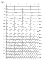
- Fig. 1 shows a U / t diagram of a clock period with a Cycle time of a total of 32 network half-waves, i.e. H. 16 Grid periods, which at a grid frequency of 50 Hz Corresponds to a cycle time of 320 ms.
- FIG. 1 shows a total of 17 patterns according to the invention specified in which the for different Power settings from a power controller switched network half-waves are shown. Out of it it is clearly recognizable that in the performance settings of 0% to 25% only isolated, time-spaced Half waves relatively evenly over the duration of the clock period are distributed. In the power levels from 31.25% to 43.75% are at least partially spaced, single half-waves available. In the performance levels from 50% up to and including 93.75% of the half waves are found on each End of cycle time.
- FIGS. 2 and 3 the first two completed U / t charts Half-wave pattern according to the invention according to FIG. 1 drawn.
- the clock cycle of the second power controller is after the end of the first switch-on time of the first Power controller started delayed by one network period. This results in a total network load according to the accumulated pattern, as in the last diagram is drawn.
- Fig. 3 are two unequal individual performances of 31.25% and 68.75% added. Except for a few, the amplitude doubled Half waves result on average over the duration of the Cycle period a relatively uniform network load. The more Devices are synchronized, the more uniform the Network load.
- Power controller L results from FIG. 4.
- Signal output A of a preceding actuator L is in each case with a Signal input E of a subsequent actuator connected.
- the control logic contained in the power controllers L starts one clock period offset by one network period the beginning of the blocking period of a previous controller, so that there are overlaps, such as in FIG. 2 or Fig. 3.
- the advantages of the procedure and the circuit arrangement shown are essentially have already been explained.
Landscapes
- Engineering & Computer Science (AREA)
- Power Engineering (AREA)
- Control Of Electrical Variables (AREA)
- Remote Monitoring And Control Of Power-Distribution Networks (AREA)
- Power Conversion In General (AREA)
- Dc-Dc Converters (AREA)
- Transmitters (AREA)
Abstract
Description
- Fig. 1
- U/t-Diagramme von erfindungsgemäßen Abfolgen von Netzhalbwellen;
- Fig. 2
- ein erstes Beispiel für eine Überlagerung zweier gleichartiger Anordnungen gemäß Figur 1;
- Fig. 3
- ein zweites Beispiel für eine Überlagerung zweier ungleicher Anordnungen gemäß Figur 1;
- Fig. 4
- eine schematisch dargestellte Schaltungsanordnung gemäß der Erfindung.
Claims (8)
- Verfahren zum Betrieb parallel geschalteter Leistungssteller an einem Wechselstromnetz, die zur Leistungssteuerung innerhalb von Taktperioden mit festlegten Zykluszeiten von mehreren Wechselstromperioden für vorgebbare Einschaltzeiten eingeschaltet werden, wobei die Einschaltung der einzelnen Leistungssteller synchronisierbar ist zur Vergleichmäßigung des entnommenen Netzstroms, dadurch gekennzeichnet, daß die Leistungssteller (L) zumindest teilweise gemäß einer vorgegebenen zeitlichen Abfolge von vereinzelten, zeitlich beabstandeten Netzhalbwellen eingeschaltet werden.
- Verfahren nach Anspruch 1, dadurch gekennzeichnet, daß die zeitliche Abfolge innerhalb einer Taktperiode die gleiche Anzahl von einzelnen Halbwellen jeweils unterschiedlicher Polarität umfaßt.
- Verfahren nach Anspruch 1 oder 2, dadurch gekennzeichnet, daß im Mittel auf eine einzelne Halbwelle eine einzelne Halbwelle umgekehrter Polarität folgt.
- Verfahren nach einem der Ansprüche 1 bis 3, dadurch gekennzeichnet, daß die Taktperiode eines auf einen vorangehenden Leistungssteller nachfolgenden Leistungsstellers im Anschluß an die erste Netzhalbwelle / Netzperiode der Einschaltzeit des vorangehenden Leistungstellers gestartet wird.
- Verfahren nach einem der Ansprüche 1 bis 4, dadurch gekennzeichnet, daß die Taktperiode des nachfolgenden Leistungstellers mit einer Halbwelle umgekehrter Polarität bezüglich der letzten Halbwelle des vorangehenden Stellers beginnt.
- Verfahren nach einem der Ansprüche 1 bis 5, dadurch gekennzeichnet, daß die Zykluslänge einer Taktperiode zumindest dem Produkt aus der Anzahl der Leistungssteller und der Netzperiode entspricht.
- Schaltungsanordnung zur Durchführung des Verfahrens nach Ansprüchen 1 bis 6, mit mindestens zwei Leistungsstellern, die parallel an ein Wechselstromnetz anschließbar sind, und an denen Verbraucher anschließbar sind, dadurch gekennzeichnet, daß von einem Leistungssteller in zyklisch wiederholbaren Taktperioden gemäß einer vorgebbaren zeitlichen Abfolge vereinzelte, zeitlich beabstandete Netzhalbwellen durchschaltbar sind.
- Schaltungsanordnung nach Anspruch 7, dadurch gekennzeichnet, daß die Leistungssteller jeweils einen Eingang aufweisen, wobei dieser Eingang eines nachfolgenden Leistungsstellers jeweils an den Ausgang eines vorangehenden Leistungsstellers anschließbar ist.
Applications Claiming Priority (2)
| Application Number | Priority Date | Filing Date | Title |
|---|---|---|---|
| DE10020865 | 2000-04-28 | ||
| DE10020865A DE10020865A1 (de) | 2000-04-28 | 2000-04-28 | Verfahren zum Betrieb von Leistungsstellern und Schaltungsanordnung zur Durchfuhrung des Verfahrens |
Publications (3)
| Publication Number | Publication Date |
|---|---|
| EP1150419A2 true EP1150419A2 (de) | 2001-10-31 |
| EP1150419A3 EP1150419A3 (de) | 2002-07-24 |
| EP1150419B1 EP1150419B1 (de) | 2004-09-22 |
Family
ID=7640222
Family Applications (1)
| Application Number | Title | Priority Date | Filing Date |
|---|---|---|---|
| EP01108709A Expired - Lifetime EP1150419B1 (de) | 2000-04-28 | 2001-04-06 | Verfahren zum Betrieb von Leistungsstellern und Schaltungsanordnung zur Durchführung des Verfahrens |
Country Status (3)
| Country | Link |
|---|---|
| EP (1) | EP1150419B1 (de) |
| AT (1) | ATE277453T1 (de) |
| DE (2) | DE10020865A1 (de) |
Cited By (3)
| Publication number | Priority date | Publication date | Assignee | Title |
|---|---|---|---|---|
| DE10160912B4 (de) * | 2001-12-12 | 2007-03-29 | Lauda Dr. R. Wobser Gmbh & Co. Kg | Verfahren und Einrichtung zur Steuerung des von mindestens zwei elektrischen Verbrauchern gleicher Leistungsaufnahme, insbesondere Heizkörpern, aufgenommenen Wechselstroms |
| EP2346150A1 (de) * | 2010-01-14 | 2011-07-20 | AEG Power Solutions B.V. | Modulare Spannungsversorgungsanordnung, insbesondere für Reaktoren zur Herstellung von Polysilicium |
| EP2369730A3 (de) * | 2010-03-24 | 2017-08-09 | Advanced Energy Industries Gmbh | Verfahren zum Einstellen der Ausgangsleistung eines Leistungstellers und Leistungssteller |
Families Citing this family (2)
| Publication number | Priority date | Publication date | Assignee | Title |
|---|---|---|---|---|
| DE20312784U1 (de) | 2003-08-19 | 2003-10-30 | Kafaee Razavi, Ahmad, Mashhad | Vorrichtung zur Kontrolle der Verbraucherspannung bei einem Mehrphasenwechselstromverbraucher |
| PL2187516T3 (pl) | 2008-11-14 | 2015-12-31 | Advanced Energy Ind Gmbh | Układ połączonych równolegle nastawników mocy do równomiernego rozdzielania poboru mocy z sieci napięcia przemiennego |
Family Cites Families (4)
| Publication number | Priority date | Publication date | Assignee | Title |
|---|---|---|---|---|
| DE3430786C2 (de) * | 1984-08-17 | 1986-07-31 | Licentia Patent-Verwaltungs-Gmbh, 6000 Frankfurt | Schwingungspaketsteuerung von Leistungsstellgliedern mit variabler Taktfrequenz |
| DE4437966C1 (de) * | 1994-10-24 | 1995-11-02 | Licentia Gmbh | Verfahren zum Betreiben parallel geschalteter Leistungssteller und Schaltungsanordnung zu seiner Durchführung |
| FR2757708B1 (fr) * | 1996-12-23 | 1999-01-29 | Schneider Electric Sa | Appareil electrique comportant un dispositif de controle de charge |
| DE19728333C2 (de) * | 1997-07-03 | 2000-04-13 | Stiebel Eltron Gmbh & Co Kg | Verfahren und Einrichtung zur Leistungssteuerung eines elektrischen Heizgeräts |
-
2000
- 2000-04-28 DE DE10020865A patent/DE10020865A1/de not_active Ceased
-
2001
- 2001-04-06 DE DE50103704T patent/DE50103704D1/de not_active Expired - Lifetime
- 2001-04-06 AT AT01108709T patent/ATE277453T1/de active
- 2001-04-06 EP EP01108709A patent/EP1150419B1/de not_active Expired - Lifetime
Cited By (4)
| Publication number | Priority date | Publication date | Assignee | Title |
|---|---|---|---|---|
| DE10160912B4 (de) * | 2001-12-12 | 2007-03-29 | Lauda Dr. R. Wobser Gmbh & Co. Kg | Verfahren und Einrichtung zur Steuerung des von mindestens zwei elektrischen Verbrauchern gleicher Leistungsaufnahme, insbesondere Heizkörpern, aufgenommenen Wechselstroms |
| EP2346150A1 (de) * | 2010-01-14 | 2011-07-20 | AEG Power Solutions B.V. | Modulare Spannungsversorgungsanordnung, insbesondere für Reaktoren zur Herstellung von Polysilicium |
| US8829711B2 (en) | 2010-01-14 | 2014-09-09 | Aeg Power Solutions B.V. | Modular power supply arrangement |
| EP2369730A3 (de) * | 2010-03-24 | 2017-08-09 | Advanced Energy Industries Gmbh | Verfahren zum Einstellen der Ausgangsleistung eines Leistungstellers und Leistungssteller |
Also Published As
| Publication number | Publication date |
|---|---|
| ATE277453T1 (de) | 2004-10-15 |
| DE10020865A1 (de) | 2001-11-15 |
| EP1150419B1 (de) | 2004-09-22 |
| EP1150419A3 (de) | 2002-07-24 |
| DE50103704D1 (de) | 2004-10-28 |
Similar Documents
| Publication | Publication Date | Title |
|---|---|---|
| EP0334112A1 (de) | Pulsumrichtergespeiste Drehfeldmaschine | |
| DE3148541A1 (de) | Spruehbeschichtungsanlage | |
| EP0491422B1 (de) | Schaltungsanordnung zur Taktumsetzung eines digitalen Signals | |
| EP1150419A2 (de) | Verfahren zum Betrieb von Leistungsstellern und Schaltungsanordnung zur Durchführung des Verfahrens | |
| EP0360349B1 (de) | Digitaler Frequenzgenerator | |
| DE4114700C2 (de) | ||
| DE3800511C1 (de) | ||
| DE69617866T2 (de) | 12V/24V X-Y-Getriebeschaltvorrichtung | |
| DE4309031A1 (de) | Verfahren zum Betreiben mehrerer parallel geschalteter Thyristorsteller | |
| EP1018793A2 (de) | Verfahren und Vorrichtung zum Schalten von Verbrauchern eines Elektrogerätes | |
| DE4303090B4 (de) | Verfahren zur Erzeugung von Führungsgrößen für Lageregelkreise in numerisch gesteuerten Maschinen | |
| DE69524019T2 (de) | Digitales Signalverarbeitungssystem | |
| DE102012010015B4 (de) | Verfahren zum Rückspeisen von Energie aus einem Zwischenkreis in ein Wechselspannungsnetz mittels ansteuerbarer Halbleiterschalter | |
| DE102018204221A1 (de) | Verfahren zur Ansteuerung eines pulsbreitenmodulierten Stromrichters und pulsbreitenmodulierter Stromrichter | |
| DE4416465C1 (de) | Verfahren zur Defuzzifizierung für signalverarbeitende Fuzzy-Baueinheiten und Filtereinrichtungen hierfür | |
| EP1012980B1 (de) | Digitaler phase locked loop | |
| EP2869450B1 (de) | Verfahren und Vorrichtung zum Festlegen der Einschaltzeitpunkte von parallel geschalteten Leistungsstellern | |
| DE29513458U1 (de) | Leistungsregler, insbesondere für Einphasen-Wechselstrommotoren, wie Lüftermotoren, die OHMsche Heizwiderstände o.dgl. | |
| DE4020093C2 (de) | Verfahren zum Einstellen der Kennlinie einer außentemperaturgeführten Heizungsregelung | |
| EP0871131A2 (de) | Vorrichtung und Verfahren zum Synchronisieren dezentraler zyklisch getakteter Baugruppen | |
| DE4030985A1 (de) | Verfahren und schaltungsanordnung zur umformung sinusaehnlicher sensorsignale eines positionsmesssystems hoher aufloesung | |
| DE10053750A1 (de) | Verfahren und Vorrichtung zur überlastungsfreien Ansteuerung eines Aktuators | |
| DE102013109300B4 (de) | Verfahren zur Ansteuerung eines Gargeräts | |
| EP2333955B1 (de) | Verfahren und Vorrichtung zum Erzeugen einer pulsweiten modulierten Signalfolge | |
| EP1063577A1 (de) | Verfahren zum Positionieren eines Schrittmotors und elektrischer Antrieb |
Legal Events
| Date | Code | Title | Description |
|---|---|---|---|
| PUAI | Public reference made under article 153(3) epc to a published international application that has entered the european phase |
Free format text: ORIGINAL CODE: 0009012 |
|
| AK | Designated contracting states |
Kind code of ref document: A2 Designated state(s): AT BE CH CY DE DK ES FI FR GB GR IE IT LI LU MC NL PT SE TR |
|
| AX | Request for extension of the european patent |
Free format text: AL;LT;LV;MK;RO;SI |
|
| PUAL | Search report despatched |
Free format text: ORIGINAL CODE: 0009013 |
|
| AK | Designated contracting states |
Kind code of ref document: A3 Designated state(s): AT BE CH CY DE DK ES FI FR GB GR IE IT LI LU MC NL PT SE TR |
|
| AX | Request for extension of the european patent |
Free format text: AL;LT;LV;MK;RO;SI |
|
| 17P | Request for examination filed |
Effective date: 20020716 |
|
| 17Q | First examination report despatched |
Effective date: 20021024 |
|
| AKX | Designation fees paid |
Designated state(s): AT BE CH CY DE DK ES FI FR GB GR IE IT LI LU MC NL PT SE TR |
|
| AXX | Extension fees paid |
Extension state: AL Payment date: 20020829 Extension state: LT Payment date: 20020829 Extension state: MK Payment date: 20020829 Extension state: SI Payment date: 20020829 Extension state: RO Payment date: 20020829 Extension state: LV Payment date: 20020829 |
|
| GRAP | Despatch of communication of intention to grant a patent |
Free format text: ORIGINAL CODE: EPIDOSNIGR1 |
|
| GRAS | Grant fee paid |
Free format text: ORIGINAL CODE: EPIDOSNIGR3 |
|
| GRAA | (expected) grant |
Free format text: ORIGINAL CODE: 0009210 |
|
| AK | Designated contracting states |
Kind code of ref document: B1 Designated state(s): AT BE CH CY DE DK ES FI FR GB GR IE IT LI LU MC NL PT SE TR |
|
| AX | Request for extension of the european patent |
Extension state: AL LT LV MK RO SI |
|
| PG25 | Lapsed in a contracting state [announced via postgrant information from national office to epo] |
Ref country code: IE Free format text: LAPSE BECAUSE OF FAILURE TO SUBMIT A TRANSLATION OF THE DESCRIPTION OR TO PAY THE FEE WITHIN THE PRESCRIBED TIME-LIMIT Effective date: 20040922 Ref country code: TR Free format text: LAPSE BECAUSE OF FAILURE TO SUBMIT A TRANSLATION OF THE DESCRIPTION OR TO PAY THE FEE WITHIN THE PRESCRIBED TIME-LIMIT Effective date: 20040922 Ref country code: FI Free format text: LAPSE BECAUSE OF FAILURE TO SUBMIT A TRANSLATION OF THE DESCRIPTION OR TO PAY THE FEE WITHIN THE PRESCRIBED TIME-LIMIT Effective date: 20040922 |
|
| REG | Reference to a national code |
Ref country code: GB Ref legal event code: FG4D Free format text: NOT ENGLISH |
|
| REG | Reference to a national code |
Ref country code: CH Ref legal event code: EP |
|
| REG | Reference to a national code |
Ref country code: IE Ref legal event code: FG4D Free format text: GERMAN |
|
| REF | Corresponds to: |
Ref document number: 50103704 Country of ref document: DE Date of ref document: 20041028 Kind code of ref document: P |
|
| PG25 | Lapsed in a contracting state [announced via postgrant information from national office to epo] |
Ref country code: DK Free format text: LAPSE BECAUSE OF FAILURE TO SUBMIT A TRANSLATION OF THE DESCRIPTION OR TO PAY THE FEE WITHIN THE PRESCRIBED TIME-LIMIT Effective date: 20041222 Ref country code: SE Free format text: LAPSE BECAUSE OF FAILURE TO SUBMIT A TRANSLATION OF THE DESCRIPTION OR TO PAY THE FEE WITHIN THE PRESCRIBED TIME-LIMIT Effective date: 20041222 Ref country code: GR Free format text: LAPSE BECAUSE OF FAILURE TO SUBMIT A TRANSLATION OF THE DESCRIPTION OR TO PAY THE FEE WITHIN THE PRESCRIBED TIME-LIMIT Effective date: 20041222 |
|
| PG25 | Lapsed in a contracting state [announced via postgrant information from national office to epo] |
Ref country code: ES Free format text: LAPSE BECAUSE OF FAILURE TO SUBMIT A TRANSLATION OF THE DESCRIPTION OR TO PAY THE FEE WITHIN THE PRESCRIBED TIME-LIMIT Effective date: 20050102 |
|
| GBT | Gb: translation of ep patent filed (gb section 77(6)(a)/1977) |
Effective date: 20050116 |
|
| LTIE | Lt: invalidation of european patent or patent extension |
Effective date: 20040922 |
|
| PG25 | Lapsed in a contracting state [announced via postgrant information from national office to epo] |
Ref country code: LU Free format text: LAPSE BECAUSE OF NON-PAYMENT OF DUE FEES Effective date: 20050406 Ref country code: CY Free format text: LAPSE BECAUSE OF FAILURE TO SUBMIT A TRANSLATION OF THE DESCRIPTION OR TO PAY THE FEE WITHIN THE PRESCRIBED TIME-LIMIT Effective date: 20050406 |
|
| REG | Reference to a national code |
Ref country code: IE Ref legal event code: FD4D |
|
| PG25 | Lapsed in a contracting state [announced via postgrant information from national office to epo] |
Ref country code: MC Free format text: LAPSE BECAUSE OF NON-PAYMENT OF DUE FEES Effective date: 20050430 |
|
| PLBE | No opposition filed within time limit |
Free format text: ORIGINAL CODE: 0009261 |
|
| STAA | Information on the status of an ep patent application or granted ep patent |
Free format text: STATUS: NO OPPOSITION FILED WITHIN TIME LIMIT |
|
| ET | Fr: translation filed | ||
| 26N | No opposition filed |
Effective date: 20050623 |
|
| PG25 | Lapsed in a contracting state [announced via postgrant information from national office to epo] |
Ref country code: PT Free format text: LAPSE BECAUSE OF NON-PAYMENT OF DUE FEES Effective date: 20050222 |
|
| PGFP | Annual fee paid to national office [announced via postgrant information from national office to epo] |
Ref country code: AT Payment date: 20140411 Year of fee payment: 14 Ref country code: CH Payment date: 20140418 Year of fee payment: 14 Ref country code: NL Payment date: 20140418 Year of fee payment: 14 |
|
| PGFP | Annual fee paid to national office [announced via postgrant information from national office to epo] |
Ref country code: BE Payment date: 20140418 Year of fee payment: 14 |
|
| REG | Reference to a national code |
Ref country code: DE Ref legal event code: R082 Ref document number: 50103704 Country of ref document: DE Representative=s name: FRITZ PATENT- UND RECHTSANWAELTE PARTNERSCHAFT, DE |
|
| REG | Reference to a national code |
Ref country code: FR Ref legal event code: PLFP Year of fee payment: 15 |
|
| REG | Reference to a national code |
Ref country code: DE Ref legal event code: R081 Ref document number: 50103704 Country of ref document: DE Owner name: ADVANCED ENERGY INDUSTRIES GMBH, DE Free format text: FORMER OWNER: AEG SVS POWER SUPPLY SYSTEMS GMBH, 59581 WARSTEIN, DE Effective date: 20150325 Ref country code: DE Ref legal event code: R082 Ref document number: 50103704 Country of ref document: DE Representative=s name: FRITZ PATENT- UND RECHTSANWAELTE PARTNERSCHAFT, DE Effective date: 20150325 |
|
| REG | Reference to a national code |
Ref country code: GB Ref legal event code: 732E Free format text: REGISTERED BETWEEN 20150514 AND 20150520 |
|
| REG | Reference to a national code |
Ref country code: FR Ref legal event code: CD Owner name: AEG POWER SOLUTIONS GMBH Effective date: 20150710 |
|
| REG | Reference to a national code |
Ref country code: CH Ref legal event code: PL |
|
| REG | Reference to a national code |
Ref country code: FR Ref legal event code: TP Owner name: ADVANCED ENERGY INDUSTRIES GMBH, DE Effective date: 20151110 |
|
| REG | Reference to a national code |
Ref country code: AT Ref legal event code: MM01 Ref document number: 277453 Country of ref document: AT Kind code of ref document: T Effective date: 20150406 |
|
| REG | Reference to a national code |
Ref country code: NL Ref legal event code: MM Effective date: 20150501 |
|
| PG25 | Lapsed in a contracting state [announced via postgrant information from national office to epo] |
Ref country code: CH Free format text: LAPSE BECAUSE OF NON-PAYMENT OF DUE FEES Effective date: 20150430 Ref country code: LI Free format text: LAPSE BECAUSE OF NON-PAYMENT OF DUE FEES Effective date: 20150430 |
|
| PG25 | Lapsed in a contracting state [announced via postgrant information from national office to epo] |
Ref country code: AT Free format text: LAPSE BECAUSE OF NON-PAYMENT OF DUE FEES Effective date: 20150406 |
|
| PG25 | Lapsed in a contracting state [announced via postgrant information from national office to epo] |
Ref country code: NL Free format text: LAPSE BECAUSE OF NON-PAYMENT OF DUE FEES Effective date: 20150501 |
|
| REG | Reference to a national code |
Ref country code: FR Ref legal event code: PLFP Year of fee payment: 16 |
|
| REG | Reference to a national code |
Ref country code: FR Ref legal event code: PLFP Year of fee payment: 17 |
|
| PG25 | Lapsed in a contracting state [announced via postgrant information from national office to epo] |
Ref country code: BE Free format text: LAPSE BECAUSE OF NON-PAYMENT OF DUE FEES Effective date: 20150430 |
|
| REG | Reference to a national code |
Ref country code: FR Ref legal event code: PLFP Year of fee payment: 18 |
|
| PGFP | Annual fee paid to national office [announced via postgrant information from national office to epo] |
Ref country code: GB Payment date: 20200325 Year of fee payment: 20 |
|
| PGFP | Annual fee paid to national office [announced via postgrant information from national office to epo] |
Ref country code: FR Payment date: 20200312 Year of fee payment: 20 |
|
| PGFP | Annual fee paid to national office [announced via postgrant information from national office to epo] |
Ref country code: DE Payment date: 20200325 Year of fee payment: 20 |
|
| PGFP | Annual fee paid to national office [announced via postgrant information from national office to epo] |
Ref country code: IT Payment date: 20200312 Year of fee payment: 20 |
|
| REG | Reference to a national code |
Ref country code: DE Ref legal event code: R071 Ref document number: 50103704 Country of ref document: DE |
|
| REG | Reference to a national code |
Ref country code: GB Ref legal event code: PE20 Expiry date: 20210405 |
|
| PG25 | Lapsed in a contracting state [announced via postgrant information from national office to epo] |
Ref country code: GB Free format text: LAPSE BECAUSE OF EXPIRATION OF PROTECTION Effective date: 20210405 |