EP1150381B1 - Antenne und funkgerät - Google Patents
Antenne und funkgerät Download PDFInfo
- Publication number
- EP1150381B1 EP1150381B1 EP99958480A EP99958480A EP1150381B1 EP 1150381 B1 EP1150381 B1 EP 1150381B1 EP 99958480 A EP99958480 A EP 99958480A EP 99958480 A EP99958480 A EP 99958480A EP 1150381 B1 EP1150381 B1 EP 1150381B1
- Authority
- EP
- European Patent Office
- Prior art keywords
- antenna
- antenna device
- radiation
- hence
- antenna elements
- Prior art date
- Legal status (The legal status is an assumption and is not a legal conclusion. Google has not performed a legal analysis and makes no representation as to the accuracy of the status listed.)
- Expired - Lifetime
Links
Images



Classifications
-
- H—ELECTRICITY
- H01—ELECTRIC ELEMENTS
- H01Q—ANTENNAS, i.e. RADIO AERIALS
- H01Q19/00—Combinations of primary active antenna elements and units with secondary devices, e.g. with quasi-optical devices, for giving the antenna a desired directional characteristic
- H01Q19/22—Combinations of primary active antenna elements and units with secondary devices, e.g. with quasi-optical devices, for giving the antenna a desired directional characteristic using a secondary device in the form of a single substantially straight conductive element
- H01Q19/26—Combinations of primary active antenna elements and units with secondary devices, e.g. with quasi-optical devices, for giving the antenna a desired directional characteristic using a secondary device in the form of a single substantially straight conductive element the primary active element being end-fed and elongated
-
- H—ELECTRICITY
- H01—ELECTRIC ELEMENTS
- H01Q—ANTENNAS, i.e. RADIO AERIALS
- H01Q11/00—Electrically-long antennas having dimensions more than twice the shortest operating wavelength and consisting of conductive active radiating elements
- H01Q11/02—Non-resonant antennas, e.g. travelling-wave antenna
- H01Q11/06—Rhombic antennas; V-antennas
-
- H—ELECTRICITY
- H01—ELECTRIC ELEMENTS
- H01Q—ANTENNAS, i.e. RADIO AERIALS
- H01Q13/00—Waveguide horns or mouths; Slot antennas; Leaky-waveguide antennas; Equivalent structures causing radiation along the transmission path of a guided wave
- H01Q13/10—Resonant slot antennas
-
- H—ELECTRICITY
- H01—ELECTRIC ELEMENTS
- H01Q—ANTENNAS, i.e. RADIO AERIALS
- H01Q21/00—Antenna arrays or systems
- H01Q21/24—Combinations of antenna units polarised in different directions for transmitting or receiving circularly and elliptically polarised waves or waves linearly polarised in any direction
-
- H—ELECTRICITY
- H01—ELECTRIC ELEMENTS
- H01Q—ANTENNAS, i.e. RADIO AERIALS
- H01Q9/00—Electrically-short antennas having dimensions not more than twice the operating wavelength and consisting of conductive active radiating elements
- H01Q9/04—Resonant antennas
- H01Q9/30—Resonant antennas with feed to end of elongated active element, e.g. unipole
- H01Q9/42—Resonant antennas with feed to end of elongated active element, e.g. unipole with folded element, the folded parts being spaced apart a small fraction of the operating wavelength
-
- H—ELECTRICITY
- H01—ELECTRIC ELEMENTS
- H01Q—ANTENNAS, i.e. RADIO AERIALS
- H01Q9/00—Electrically-short antennas having dimensions not more than twice the operating wavelength and consisting of conductive active radiating elements
- H01Q9/04—Resonant antennas
- H01Q9/44—Resonant antennas with a plurality of divergent straight elements, e.g. V-dipole, X-antenna; with a plurality of elements having mutually inclined substantially straight portions
Definitions
- the present invention relates to an antenna device used in a mobile communication system such as a PHS or the like, and a radio apparatus having the antenna device built therein.
- a high gain was required of an antenna device used in a radio base station apparatus or fixed radio terminal apparatus in a mobile communication system such as PHS or the like. Therefore, a multistage collinear array antenna was used, for example, as shown in JP-A-5-267932 , JP-A-9-232851 and JP-A-8-139521 .
- antennas non-directional in a horizontal plane with respect to vertically polarized wave were arranged multistageously vertically to narrow directivity in a vertical plane to thereby secure a high gain.
- An end-fire array antenna represented by a Yagi antenna or a reflector-containing dipole antenna was also used, for example, as shown in JP-A-5-259733 and JP-A-8-304433 .
- passive elements were arranged in parallel to the direction of main radiation to thereby secure a high gain.
- a broadside array antenna represented by a patch array antenna was further used, for example, as shown in JP-A-6-334434 .
- a plurality of antennas were arranged in a plane perpendicular to the direction of main radiation to perform distributive feeding to thereby secure a high gain.
- a low-profile antenna represented by a reflector-containing loop antenna or a slot antenna was further used, for example, as shown in JP-A-6-268432 and JP-U-6-44219 .
- an antenna formed from two one-wavelength antennas arranged into the form of a square or a circle, for example; as shown in "Antenna Handbook".(CQ Publication Co., Ltd.) p.366 is known as a broadside array antenna mainly used in a VHF band.
- the antenna of this type was unsuitable for being built in a radio apparatus because of its large area.
- the conventional low-profile antenna was formed in a small-size low-profile configuration, there was a problem that the radiation directivity could not be optimized to provide desired characteristic.
- US-A-2 207 781 describes an antenna device comprising two one-wavelength antenna elements opposite to one another, which are bent symmetrically at a given angle in a center, such that these antenna elements are arranged diamond-wise, the feeding portion being disposed at one of the ends of both antenna elements, whereas the other ends are open, and wherein the given angle can be determined in order to achieve a preferred radiation directivity.
- the present invention is designed to solve the conventional various problems generally and it is an object of the present invention to provide an antenna device in which the optimal radiation directivity can be obtained in the broadside array antenna having two one-wavelength antennas, in which a high gain and a high function can be obtained with a simple configuration and which can be used as a small-size low-profile antenna for a mobile communication system in UHF and sub-micro wave bands.
- An antenna device useful for understanding the invention comprises a first one-wavelength antenna element bent at an angle alpha in the center of the first antenna element, and a second one-wavelength antenna element bent at an angle alpha in the center of the second antenna element, wherein the first and second antenna elements are arranged in diamond-wise opposition to each other, wherein a feeding portion is disposed at one-ends of the first and second antenna elements, wherein the other-ends of the first and second antenna elements are opened, and wherein the angle alpha is selected to be an optimal angle.
- optimal radiation directivity can be obtained with a simple planar configuration.
- an antenna device having a high gain can be obtained.
- An antenna device useful for understanding the invention is configured so that a plurality of other first and second antenna elements are connected to forward ends of the first-mentioned first and second antenna elements. Hence, optimal radiation directivity improved in gain in the direction of main radiation can be obtained with a simple planar configuration. Hence, there is an effect in which an antenna device having a high gain can be obtained.
- An antenna device useful for understanding the invention is configured so that the angle alpha of bending in the center of each of the first and second antenna elements is selected to be an angle at which optimal radiation directivity can be obtained. Hence, optimal radiation directivity can be obtained with a simple planar configuration. Hence, there is an effect in which an antenna device having a high gain can be obtained.
- An antenna device useful for understanding the invention is configured so that a plurality of antenna devices defined in Claim 1 are connected in parallel with each other at the feeding portion. Hence, there is an effect in which an antenna device having a higher gain can be obtained with a simple planar configuration.
- An antenna device useful for understanding the invention is configured so that the angle alpha of bending in the center of each of the first and second antenna elements is selected to be an angle at which optimal radiation directivity can be obtained. Also in the case where a plurality of antenna devices are connected in parallel with each other at a feeding point, optimal radiation directivity can be obtained with a small-size and simple planar configuration. Hence, there is an effect in which an antenna device having a high gain can be obtained.
- An antenna device useful for understanding the invention is configured so that the first and second antenna elements are formed by a print pattern formed on a dielectric substrate. Also in the case where antenna elements are formed by a print pattern, desired radiation directivity can be obtained with a small-size and simple planar configuration. Hence, there is an effect in which an antenna device having a high gain can be obtained.
- Another antenna device useful for understanding the invention is configured so that the plurality of other first and second antenna elements are connected to the first-mentioned first and second antenna elements respectively through transmission lines each having a fixed electrical length.
- the total length of the antenna can be elongated to a desired value in the Y-plane direction, so that desired radiation directivity can be obtained.
- Another antenna device useful for understanding the invention is configured so that two pairs of the first to the fourth antenna devices defined above are arranged in such a manner that the directions of main polarization crossing perpendicularly to each other and the two pairs of antenna devices are fed with phase differences of 90 degrees from each other. Hence, desired radiation directivity can be obtained with a simple planar configuration. Hence, there is an effect in which an antenna device to achieve a circular polarization antenna having a high gain can be obtained.
- Another antenna device useful for understanding the invention is configured so that the sixth antenna device defined above is formed by print patterns disposed on opposite surfaces of a dielectric substrate. Also in the case where two pairs of antenna devices are formed by print patterns with the directions of main polarization crossing perpendicularly to each other, desired radiation directivity can be obtained with a small-size and simple planar configuration. Hence, there is an effect in which an antenna device to achieve a circular polarization antenna having a high gain can be obtained.
- Another antenna device useful for understanding the invention is configured so that the fourth and fifth antenna devices defined above are arranged in such a manner that the directions of main polarization cross perpendicularly to each other, and the plurality of antenna devices are fed with phase differences of 90 degrees from each other. Hence, desired radiation directivity can be obtained with a simple planar configuration. Hence, there is an effect in which an antenna device to achieve a circular polarization antenna having a high gain can be obtained.
- Another antenna device useful for understanding the invention is configured so that a reflection plate is provided in proximity to the antenna elements. Hence, desired radiation directivity can be obtained with a simple planar configuration. Hence, there is an effect in which an antenna device having a higher gain can be obtained.
- Another antenna device useful for understanding the invention is configured so that a plurality of passive elements are provided in proximity to the antenna elements. Hence, desired radiation directivity can be obtained with a simple planar configuration. Hence, there is an effect in which an antenna device having a high gain can be obtained.
- Another antenna device useful for understanding the invention is configured so that antenna devices defined are arranged as a radiator and a reflector, and a plurality of wave directors which are similar in shape to the antenna devices are arranged in the directions of main radiation. Hence, desired radiation directivity can be obtained with a simple configuration. Hence, there is an effect in which an antenna device having a higher gain can be obtained.
- An antenna device described in examples useful for understanding the invention is configured so that the first to sixtth antenna devices as defined above are arranged in such a manner that the directions of main polarization are made identical with one another while the directions of main radiation are made different by 90 degrees from one another, and the plurality of antennas are fed with phase differences of 90 degrees from one another.
- desired radiation directivity can be obtained with a simple configuration.
- An antenna device described in Claim 1 is configured so that a plurality of antenna devices as defined above as the first to sixth antenna devices are arranged in such a manner that the directions of main polarization are made identical with each other while the directions of main radiation are made different from each other, and opposite antenna elements of at least one antenna device among the plurality of antenna devices are partially electronically connected/disconnected to/from each other.
- radiation directivity can be changed variously with a simple configuration so as to obtain a desired radiation direction.
- a changeable directional antenna device having a high gain can be obtained.
- An antenna device described in Claim 2 is configured so that a quarter-wavelength shorting stub is connected to a feeding point so that feeding is performed at a position where impedance of the shorting stub is optimized. Hence, good impedance matching can be obtained by a small-size matching circuit with a simple configuration. Hence, there is an effect in which an antenna device having a high gain can be obtained.
- a radio apparatus described in Claim 3 is configured so that an antenna device defined in Claim 1 or 2 is built in the radio apparatus. Hence, desired optimal radiation directivity can be obtained. Hence, there is an effect in which an antenna having a high gain can be built in a radio apparatus with a small-size and simple configuration.
- An antenna device described in Claim 4 is configured so that a plurality of antenna devices defined in any one of Claims 1 through 3 are arranged. Hence, desired radiation directivity can be obtained with a small-size and simple configuration. Hence, there is an effect in which a diversity or sector antenna having a high gain can be achieved.
- An antenna device described in Claim 5 is configured so that a reflection plate is provided so as to be used in common to the plurality of antenna devices. Hence, desired radiation directivity can be obtained with a small-size and simple configuration. Hence, there is an effect in which a diversity or sector antenna having a high gain can be achieved.
- a radio base station described in Claim 6 is configured so that the radio base station is provided with an antenna device defined in Claim 5. Hence, desired radiation directivity can be obtained with a small-size and simple configuration. Hence, there is an effect in which a diversity or sector antenna having a high gain can be used.
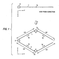
- Fig. 1 is a view showing the configuration of the antenna device according to the first example useful for understanding the present invention.
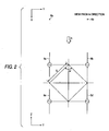
- Fig. 2 is a typical view for explaining the operation of the antenna device shown in Fig. 1 .
- Fig. 3 is a graph showing the radiation pattern in a horizontal plane of the antenna device shown in Fig. 1 .
- Fig. 4 is a graph showing the radiation pattern in a vertical plane of the antenna device shown in Fig. 1 .
- the reference numeral 1 designates a first antenna element; 2, a second antenna element; 3, a feeding portion; 4, an opening portion; and 1 a and 2a, bent portions.
- Each of the first and second antenna elements 1 and 2 is constituted by a conductor wire with a length of one wavelength.
- the first and second antenna elements 1 and 2 are bent at an angle alpha in the bent portions 1a and 2a respectively.
- the first and second antenna elements 1 and 2 are arranged in diamond-wise opposition to each other as shown in Fig. 1 .
- Each side of the diamond shape has a half wavelength ( lambda /2).
- the feeding portion 3 is provided at one-ends of the first and second antenna elements 1 and 2 respectively.
- the other-ends of the first and second antenna elements 1 and 2 are electrically opened as represented by the opening portion 4.
- the length of each of the first and second antenna elements 1 and 2 is about 158mm and each side of the diamond shape is 79mm.
- the angle alpha is selected to be approximately in a range of from 30 to 150 degrees.
- the antenna device when the feeding portion 3 is excited by a high-frequency signal, currents distributed in the first and second antenna elements 1 and 2 are as represented by the arrows 5a to 5d because each side of the diamond shape has a half wavelength (lambda /2).
- the antenna device operates so that respective horizontal components (Y-axis components) of the currents 5a to 5d cancel one another whereas respective vertical components (Z-axis components) of the currents 5a to 5d intensity one another.
- vertically (Z-axis) polarized electric wave is radiated.
- the radiation of the vertically (Z-axis) polarized electric wave is maximized in the X direction and in the -X direction in Fig. 1 . In this case, a directional gain of about 6dB is obtained.
- This operation is equivalent to that of an array antenna constituted by four half-wavelength dipole antennas arranged as shown in Fig. 2 .
- the reference numerals 6a to 6d designate vertical polarization half-wavelength dipole antennas.
- the dipole antennas 6a to 6d are arranged with vertical and horizontal arrangement intervals determined on the basis of the angle alpha ' and distance S between the dipole antennas 6a to 6d.
- intensive radiation synthesized in the X-axis direction is generated.
- the pattern of the radiation is determined on the basis of arrangement coefficients owing to the vertical and horizontal arrangement intervals.
- Fig. 3 is a graph showing the radiation pattern of vertically polarized wave in a horizontal plane (XY plane) in each of the antenna devices shown in Figs. 1 and 2 .
- the horizontal axis indicates an angle (degrees) of radiation and the angle of 0 degree indicates the X direction.
- the vertical axis indicates a radiation level relative value normalized by a level in a maximum radiation direction.
- the reference numeral 7 designates a radiation pattern in the case where the angle alpha of each of the bent portions 1a and 2a of the antenna device in Fig. 1 is equal to 60 degrees.
- the reference numeral 8 designates a radiation pattern in the case where the angle alpha ' between the dipole antennas in Fig. 2 is equal to 60 degrees.
- the reference numeral 9 designates a radiation pattern in the case where the angle alpha of each of the bent portions 1a and 2a of the antenna device in Fig. 1 is equal to 120 degrees.
- the reference numeral 10 designates a radiation pattern in the case where the angle alpha ' between the dipole antennas in Fig. 2 is equal to 120 degrees.
- Fig. 4 is a graph showing the radiation pattern of vertically polarized wave in a vertical plane (XZ plane) in each of the antenna devices shown in Figs. 1 and 2 .
- the reference numerals 7 to 10 designate radiation patterns similar to those in Fig. 3 .
- the radiation patterns in the horizontal plane and in the vertical plane can be changed greatly.
- the half-value width (the width of the radiation angle to obtain -3dB) of the radiation pattern in the horizontal plane decreases from 118 degrees to 64 degrees, while the half-value width of the radiation pattern in the vertical plane increases from 50 degrees to 68 degrees.
- the array antenna shown in Fig. 2 has this tendency similarly.
- the angle alpha of each of the bent portions 1 a and 2a is changed to increase from 30 degrees to 150 degrees, the half-value width of the radiation pattern in the horizontal plane changes from approximately non-directivity to 47 degrees and the half-value width of the radiation pattern in the vertical plane increases from 50 degrees to 80 degrees.
- radiation patterns in the horizontal plane and in the vertical plane can be controlled by changing the angle alpha .
- an antenna having desired directivity and having a high gain can be achieved with a simple planar configuration.
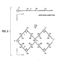
- FIG. 5 is a view showing the configuration of the antenna device according to the second example useful for understanding the present invention.
- the reference numeral 3 designates a feeding portion; 4, an opening portion; 11, a first antenna element; 12, a second antenna element; and 11a, 11 b, 11c, 12a, 12b and 12c, bent portions.
- the first and second antenna elements 11 and 12 are arranged so oppositely that two diamond-shaped antenna devices each constituted by first and second antenna elements 1 and 2 as shown in Fig. 1 are connected to each other.
- the length of each side of the diamond shape is equal to a half wavelength ( lambda /2). That is, each of the first and second antenna elements 11 and 12 is constituted by a conductive wire having a length equal to two wavelengths.
- the first and second antenna elements 11 and 12 are bent at an angle alpha in the bent portions 11 a to 11 c and 12a to 12c respectively.
- the feeding portion 3 is provided at one-ends of the first and second antenna elements 11 and 12 respectively.
- the opposite ends of the first and second antenna elements 11 and 12 are electrically opened as shown by the opening portion 4.
- This operation is approximately equivalent to the operation of an array antenna in which two antenna devices according to the first example as shown in Fig. 1 are arranged in the Y direction.
- radiation patterns in the horizontal plane and in the vertical plane can be changed greatly by changing the angle alpha .
- the angle alpha is changed to increase from 60 degrees to 120 degrees
- the half-value width of the radiation pattern in the horizontal plane decreases from 50 degrees to 30 degrees while the half-value width of the radiation pattern in the vertical plane increases from 50 degrees to 68 degrees.
- the half-value width of the radiation pattern in the horizontal plane is reduced to about a half compared with the antenna device according to the first example as shown in Fig. 1 .
- radiation patterns in the horizontal plane and in the vertical plane can be controlled by changing the angle alpha .
- an antenna having desired directivity and having a high gain can be achieved with a simple planar configuration.
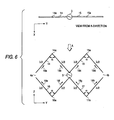
- FIG. 6 is a view showing the configuration of the antenna device according to the third example useful for understanding the present invention.
- the reference numeral 3 designates a feeding portion; 4a and 4b, opening portions; 14 and 15, first antenna elements; 16 and 17, second antenna elements; and 14a, 15a, 16a and 17a, bent portions.
- Each of the first and second antenna elements 14 to 17 is constituted by a conductive wire having a length equal to one wavelength.
- the first and second antenna elements 14 to 17 are bent at an angle alpha in the bent portions 14a to 17a respectively.
- the first antenna elements 14 and 15 and the second antenna elements 16 and 17 are connected as shown in Fig. 6 .
- the feeding portion 3 is provided in junction portions between the first antenna elements 14 and 15 and between the second antenna elements 16 and 17. Other ends are electrically opened as represented by the opening portions 4a and 4b.
- This operation is approximately equivalent to the operation of an array antenna in which two antenna devices according to the first embodiment as shown in Fig. 1 are arranged so as to be fed in parallel in the Y direction.
- the change of radiation patterns in the case where the angle alpha is changed is approximately equivalent to that in the antenna device according to the second element in Fig. 5 .
- feeding-point impedance is reduced to a value not higher than a half of that of the antenna device according to the first example as shown in Fig. 1 to be thereby favorable for matching the impedance with the transmission line.
- the feeding-point impedance can be reduced and the radiation patterns in the horizontal plane and in the vertical plane can be controlled by changing the angle alpha .
- an antenna having desired directivity and having a high gain can be achieved with a simple planar configuration.
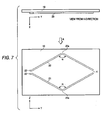
- FIG. 7 is a view showing the configuration of the antenna device according to the fourth example useful for understanding the present invention.
- the reference numeral 4 designates an opening portion; 19, a dielectric substrate; 20, a first antenna pattern as a first antenna element; 21, a second antenna pattern as a second antenna element; 22 and 23, feeding terminals; and 20a and 21 a, bent portions.
- Each of the first and second antenna patterns 20 and 21 is constituted by a print pattern formed on the dielectric substrate 19.
- the first and second antenna patterns 20 and 21 are bent at an angle alpha in the bent portions 20a and 21 a respectively.
- the length of each of the first and second antenna patterns 20 and 21 is selected to be equal to one wavelength on the dielectric substrate.
- the effective relative dielectric constant of the dielectric substrate is 2
- the length of each of the first and second antenna patterns 20 and 21 is about 80mm for the operating frequency of 1900MHz because the wavelength on the dielectric substrate is reduced to about a half of the wavelength in a free space.
- the operation of the antenna device according to this example will be described below.
- the antenna device configured as described above, when the feeding terminals 22 and 23 are excited by a high-frequency signal, the antenna device operates in the same manner as in the antenna device according to the first example in Fig. 1 . Hence, more detailed description will be omitted.
- an antenna having desired directivity and having a high gain can be achieved with a small-size and simple planar configuration by a print pattern on a dielectric substrate.
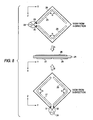
- FIG. 8 is a view showing the configuration of the antenna device according to the fifth example useful for understanding the present invention.
- the reference numeral 24 designates a dielectric substrate; 25, 26, 27 and 28, antenna patterns as antenna elements; 29, 30, 31 and 31, feeding terminals; and 33 and 34, high-frequency signal sources.
- the antenna patterns 25 and 26 are constituted by a print pattern formed on one surface of the double-side copper-clad dielectric substrate 24, while the antenna patterns 27 and 28 are constituted by a print pattern formed on the other surface of the double-side copper-clad dielectric substrate 24.
- the length of each of the antenna patterns 25, 26, 27 and 28 is selected to be equal to one wavelength on the dielectric substrate.
- a combination of the antenna patterns 25 and 26 and the feeding portions 29 and 30 and a combination of the antenna patterns 27 and 28 and the feeding portions 31 and 32 serve as independent antennas.
- Each of the antennas operates in the same manner as in the antenna device according to the fourth example in Fig. 7 .
- the antenna patterns 25 and 26 radiate vertically (Z-direction) polarized wave whereas the antenna patterns 27 and 28 radiate horizontally (Y-direction) polarized wave.
- the phases of the high-frequency signal sources 33 and 34 are selected to be made different by 90 degrees from each other, circularly polarized electric wave is radiated in the X direction and in the -X direction, so that a directional gain of about 6dB is obtained.
- left-handed circularly polarized wave or right-handed circularly polarized wave is radiated either in the X direction or in the -X direction.
- the rotational direction is determined on the basis of the lag-lead relation between the phases of the high-frequency signal sources 33 and 34.
- a circular polarization antenna having desired directivity and having a high gain can be achieved with a small-size and simple planar configuration by print patterns on a dielectric substrate.
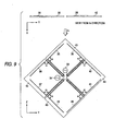
- FIG. 9 is a view showing the configuration of the antenna device according to the sixth example useful for understanding the present invention.
- the reference numerals 33 and 34 designate high-frequency signal sources; 35, 36, 37, 38, 39, 40, 41 and 42, antenna elements; 43, a horizontal polarization antenna system; and 44, a vertical polarization antenna system.
- the antenna elements 35, 36 and 39, 40 are excited by the high-frequency signal source 33, so that they serve as a horizontal polarization antenna system 43 which operates in the same manner as the antenna device according to the third example in Fig. 6 .
- the antenna elements 38, 39 and 41, 42 are excited by the high-frequency signal source 34, so that they serve as a vertical polarization antenna system 44 which operates in the same manner as the antenna device according to the third example in Fig. 6 .
- the horizontal polarization antenna system 43 and the vertical polarization antenna system 44 are arranged so as to cross perpendicularly to each other in the YZ plane.
- a circular polarization antenna having desired directivity and having a high gain can be achieved with a simple planar configuration.
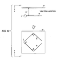
- FIG. 10 is a view showing the configuration of the antenna device according to the seventh example useful for understanding the present invention.
- the reference numeral 3 designates a feeding portion; 45, a reflection plate; and 46 and 47, antenna elements.
- the antenna elements 46 and 47 operate in the same manner as in the antenna device according to the first example in Fig. 1 , so that maximum radiation is generated in the X direction and in the -X direction.
- the antenna elements 46 and 47 are arranged so as to be distanced from the reflection plate 45 by a distance indicated by the reference numeral 48.
- the wave radiated in the -X direction is reflected by the reflection plate 45, so that the reflected wave is radiated in the X direction.
- radiation patterns are concentrated into the X direction.
- the distance 48 is selected to be about 0.3 lambda (0.3 times as large as the wavelength)
- a directional gain of about 9.5dB can be obtained in the X direction.
- radiation patterns in the horizontal plane and in the vertical plane can be controlled by changing the angle alpha in the bent portions.
- an antenna device having desired directivity and having a high gain can be achieved with a simple planar configuration.
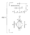
- Fig. 11 is a view showing the configuration of the antenna device according to the eighth example useful for understanding the present invention.
- the reference numeral 3 designates a feeding portion; 49, a reflection plate; 50 and 51, antenna elements; and 52 and 53, passive elements.
- the antenna elements 50 and 51 operate in the same manner as in the antenna device according to the first example in Fig. 1 . Further, the antenna elements 50 and 51 are arranged so as to be separated by a distance 54 from the reflection plate 49.
- Each of the passive elements 52 and 53 is constituted by a conductive wire which is slightly shorter than a half wavelength.
- the passive elements 52 and 53 are arranged in positions which are separated by a distance 55 in the X direction from the antenna elements 52 and 53 and which are separated by a distance 56 in the Y and -Y directions from the center respectively.
- each of the distances 54 and 55 is selected to be about 0.3 lambda (0.3 times as large as the wavelength) and the distance 56 is selected to be about 0.4 lambda (0.4 times as large as the wavelength)
- wide-angle directivity of 180 degrees as a half-value width can be obtained in the X direction, so that a directional gain of about 6.5dB can be obtained.
- an antenna device having wide-angle directivity of 180 degrees as a half-value width and having a high gain can be achieved with a simple configuration.
- FIG. 12 is a view showing the configuration of the antenna device according to the ninth example useful for understanding the present invention.
- the reference numeral 3 designates a feeding portion; and 57, 58, 59, 60, 61 and 62, antenna elements.
- the antenna elements 57 and 58 and the feeding portion 3 operate in the same manner as in the antenna device according to the first example in Fig. 1 , so that they serve as a radiator.
- Each of the antenna elements 59 and 60 is selected to have a length longer by about 4% than that of each of the antenna elements 57 and 58.
- the antenna elements 59 and 60 are arranged so as to be separated by about 0.2 lambda (0.2 times as large as the wavelength) in the -X direction from the antenna elements 57 and 58, so that they serve as a reflector. Further, each of the antenna elements 61 and 62 is selected to have a length shorter by about 8% than that of each of the antenna elements 57 and 58. The antenna elements 61 and 62 are arranged so as to be separated by about 0.2 lambda (0.2 times as large as the wavelength) in the X direction from the antenna elements 57 and 58, so that they serve as a wave director.
- the antenna device configured as described above operates as a whole in the same manner as a Yagi antenna. Hence, radiation directivity is concentrated into the X direction, so that a directional gain of about 11 dB is obtained.
- this example has shown the case where a three-element Yagi antenna is formed, a higher gain can be obtained if a larger number of elements are arranged. When, for example, 5 elements are provided, a directional gain of about 12.5dB can be obtained. Also in this example, directivity in the vertical plane and in the horizontal plane can be changed by changing the angle alpha in the bent portions.
- a Yagi antenna having desired directivity and having a high gain can be achieved with a simple configuration.
- FIG. 13 is a view showing the configuration of the antenna device according to the tenth example useful for understanding the present invention.
- the reference numerals 63, 64, 65 and 66 designate antenna elements; and 67 and 68, high-frequency signal sources.
- the antenna elements 63 and 64 and the feeding portion 67 operate in the same manner as in the antenna device according to the first example in Fig. 1 .
- the antenna elements 65 and 66 and the feeding portion 68 also operate in the same manner as in the antenna device according to the first example in Fig. 1 .
- the antenna elements 63, 64 and 65, 66 are arranged so that the direction of main polarization in the antenna elements 63 and 64 is identical with that in the antenna elements 65 and 66 in terms of horizontally polarized wave, whereas the directions of main radiation cross perpendicularly to each other.
- the antenna device When the antenna element 63 and 64 and the antenna element pair 65 and 66 are supplied with high-frequency signals 67 and 68 respectively so that the phases of the signals are made different by 90 degrees from each other, the antenna device exhibits non-directional radiation characteristic in the horizontal plane in terms of horizontally polarized wave, so that a gain of about 3.5dB can be obtained.
- directivity in the vertical plane and in the horizontal plane can be changed by changing the angle alpha in the bent portions.
- a horizontal non-directional antenna having a high gain can be achieved with a simple configuration.
- FIG. 14 is a view showing the configuration of the antenna device according to the eleventh example useful for understanding the present invention.
- the reference numerals 69, 70, 71, 72, 73, 74, 75 and 76 designate antenna elements; and 77, a high-frequency signal source.
- the feeding portion 77 and the antenna elements 69, 70 and 71, 72 operate in the same manner as in the antenna device according to the third example in Fig. 6 .
- the antenna elements 73, 74, and 75, 76 are connected in parallel to the antenna elements 69, 70 and 71, 72 so that the directions of main polarization are made identical with each other whereas the directions of main radiation cross perpendicularly to each other.
- the antenna device configured as described above exhibits radiation characteristic in which the radiation directivity in the horizontal plane in terms of vertically polarized wave is concentrated into the four directions X, -X, Y and -Y. A gain of about 5.5dB is obtained in each of the four directions. Radiation characteristic of about 30 degrees as a half-value width can be obtained.
- the directivity in the vertical plane and in the horizontal plane can be changed by changing the angle alpha in the bent portions.
- a 4-directional antenna having desired directivity and having a high gain can be achieved with a simple configuration.
- FIG. 15 is a view showing the configuration of the antenna device according to this first embodiment of the present invention.
- the reference numerals 78, 79, 80, 81, 82 and 83 designate antenna elements; 84, a feeding portion; 85, a reflection plate; 86, 87, 88 and 89, high-frequency switches; and 90 and 91, shorting lines.
- the antenna elements 78, 79 and 80, 81 and the feeding portion 84 operate in the same manner as in the antenna device according to the third example in Fig. 6 .
- the antenna elements 82 and 83 are connected in parallel to the antenna elements 78, 79 and 80, 81.
- the antenna elements are arranged so that the directions of main polarization are made identical with each other whereas the directions of main radiation cross perpendicularly to each other.
- the high-frequency switches 86 and 87 and the shorting line 90 are connected to the antenna elements 78 and 79 at points.
- the antenna elements 78 and 79 and the shorting line 90 serve as a quarter-wavelength shorting stub in which the antenna elements do not contribute to radiation.
- the antenna elements 80 and 81, the high-frequency switches 88 and 89 and the shorting line 91 operate in the same manner as described above.
- the reflection plate 85 is arranged so as to be separated by a distance 92 in the -X direction from the antenna elements 78, 79 and 80, 81.
- the operation of the antenna device according to this embodiment will be described below.
- the antenna elements 78 and 79 do not contribute to radiation so that radiation is concentrated into an intermediate direction between the X direction and the Y direction.
- a gain of about 9dB is obtained and radiation directivity of about 80 degrees as a half-value width is obtained.
- the high-frequency switches 86 and 87 are turned off while the high-frequency switches 88 and 89 are turned on, the direction of maximum radiation is directed to the intermediate direction between the X direction and the -Y direction.
- the directivity in the vertical plane and in the horizontal plane can be changed by changing the angle alpha in the bent portions.
- antenna elements opposite to each other are partially connected/disconnected to/from each other by electronic switches to thereby obtain desired directivity.
- a changeable directional antenna having a high gain can be achieved with a simple configuration.
- Fig. 16 is a view showing the configuration of the antenna device according to the second embodiment.
- the reference numerals 93 and 94 designate antenna patterns (antenna elements); 95, a quarter-wavelength shorting stub; 96, a dielectric substrate; and 99, a high-frequency signal cable.
- the antenna patterns 93 and 94 and the quarter-wavelength shorting stub 95 are constituted by a print pattern formed on the dielectric substrate 96.
- the antenna patterns 93 and 94 operate in the same manner as in the antenna device according to the fourth example in Fig. 7 .
- Impedance in the feeding portion 97 between the antenna patterns 93 and 94 reaches a high value of several k OMEGA.
- the impedance generally 50 OMEGA
- the high-frequency signal cable 99 is connected to the quarter-wavelength shorting stub 95 at optimal positions 98.
- the quarter-wavelength shorting stub 95 does not increase the total area of the antenna because the stub 95 is disposed inside the antenna patterns 93 and 94.
- a matching circuit is formed by the print pattern on the dielectric substrate.
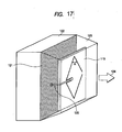
- Fig. 17 is a view showing the configuration of the antenna device according to this embodiment.
- the reference numeral 119 designates an antenna device; 120, a high-frequency cable; 121, a reflection plate; 122, a radio circuit portion; and 123, an antenna cover.
- the reflection plate 121 is disposed on one side surface of the radio circuit portion 122.
- the antenna device 119 is disposed so as to be separated by a fixed distance (for example, 0.3 lambda) from the reflection plate 121.
- the high-frequency cable 120 is connected from the radio circuit portion 122 to the antenna device 119 so that the antenna device 119 is fed.
- the antenna device 119 is protected by the antenna cover 123.
- the antenna device 119 operates in the same manner as the antenna device according to the second embodiment shown in Fig. 16 .
- the operation of the radio apparatus according to this embodiment will be described below.
- radiation from the antenna device 119 is concentrated into the direction of the arrow 124 by the reflection plate 121.
- a directional gain of about 9.5dB can be obtained.
- antenna characteristic is not affected by the radio circuit portion 122.
- the radio circuit portion 122 is not affected by electric wave radiated from the antenna device 119.
- the distance between the reflection plate 121 and the antenna device 119 is about 0.3 lambda (about 45mm for the operating frequency of 1900MHz). Accordingly, the radio apparatus having the built-in antenna can be made compact. Hence, if the radio apparatus is applied to a fixed terminal equipment or to a radio base station, desired radiation directivity can be obtained with a small-size and simple configuration. Hence, a fixed terminal equipment or a radio base station with a built-in antenna having a high gain can be achieved.
- the configuration of the radio apparatus and the antenna device is not limited to this embodiment and the same effect as described above can be obtained if the same structure as described above is provided.
- a radio apparatus with a built-in antenna having desired directivity and having a high gain can be achieved with a small-size and simple configuration.
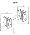
- Fig. 18 is a view showing the configuration of the antenna device according to this embodiment.
- the reference numerals 125, 126, 127 and 128 designate antenna devices; 129 and 130, reflection plates; 131, 132, 133, 134 and 135, fittings; 136, a first antenna system; 137, a second antenna system; and 138, a pole.
- the antenna devices 125, 126, 127 and 128 operate in the same manner as the antenna device according to the second embodiment shown in Fig. 16 .
- the antenna devices 125 and 126 are arranged in 180 degrees-opposition to each other through the reflection plate 129 and fixed by the fittings 131 and 132.
- a first antenna system 136 is formed.
- the antenna devices 127 and 128 are arranged in 180 degrees-opposition to each other through the reflection plate 130 and fixed by the fittings 133 and 134.
- a second antenna system 137 is formed.
- the first and second antenna systems 136 and 137 are fixed to each other by the fittings 135 so as to be separated by a fixed distance (generally a distance of one wavelength or larger) from each other, so that they serve as a diversity antenna.
- the antenna device 125 exhibits radiation directivity of about 180 degrees as a half-value width in the X direction because of the effect of the reflection plate 129, so that the gain in the -X direction becomes lower by about 10dB than the gain in the X direction.
- the antenna device 126 exhibits radiation directivity of about 180 degrees as a half-value width in the -X direction because of the effect of the reflection plate 129, so that the gain in the X direction becomes lower by about 10dB than the gain in the -X direction.
- the reflection plate 129 is used in common to the antenna devices 125 and 126.
- the second antenna system 137 operates in the same manner as the first antenna system 136.
- the antenna device and the arrangement and configuration thereof are not limited to this embodiment and the same effect as described above can be obtained if the same structure as described above is provided.
- a sector diversity antenna constituted by a plurality of antennas arranged therein and having a high gain with desired directivity can be achieved with a small-size and simple configuration.
Landscapes
- Variable-Direction Aerials And Aerial Arrays (AREA)
- Waveguide Aerials (AREA)
Claims (6)
- Antennenvorrichtung, die mehrere Antennen umfasst, von denen jede umfasst:ein erstes Einwellenlängen-Antennenelement (78, 80), das in einer Mitte des ersten Antennenelementes in einem Winkel α gebogen ist, undein zweites Einwellenlängen-Antennenelement (79, 81), das in einer Mitte des zweiten Antennenelementes in dem Winkel α gebogen ist,wobei das erste und das zweite Antennenelement (78, 79, 80, 81) einander in Rautenform gegenüberliegen und ein Speiseabschnitt (84) jeweils an einem Ende des ersten und des zweiten Antennenelementes angeordnet ist, die anderen Enden des ersten und des zweiten Antennenelementes (78, 79, 80, 81) offen sind und der Winkel α so ausgewählt wird, dass er einer gewünschten Strahlungsrichtung entspricht;dadurch gekennzeichnet, dassdie Vielzahl von Antennen so angeordnet sind, dass Richtungen der Hauptpolarisation identisch miteinander sind, während sich Richtungen der Hauptstrahlung voneinander unterscheiden, und wobei einander gegenüberliegende Antennenelemente wenigstens einer Antenne der Vielzahl von Antennen (78, 79, 80, 81) elektronisch geschaltet werden können, um sie miteinander zu verbinden/voneinander zu trennen.
- Antennenvorrichtung nach Anspruch 1, wobei eine Viertelwellenlängen-Kurzschlussstichleitung (95) mit dem Speiseabschnitt (98) wenigstens einer der enthaltenen Antennen so verbunden ist, dass Speisen an einer Position durchgeführt wird, an der die Impedanz der Kurzschlussstichleitung (95) optimiert ist.
- Funkgerät, wobei eine Antennenvorrichtung nach Anspruch 1 oder Anspruch 2 in das Funkgerät eingebaut ist.
- Antennenvorrichtung für eine Funk-Basisstation, in der eine Vielzahl von Antennenvorrichtungen nach Anspruch 1 oder Anspruch 2 angeordnet sind.
- Antennenvorrichtung nach Anspruch 4, wobei eine Reflektionsplatte (85) so vorhanden ist, dass sie gemeinsam von der Vielzahl von Antennenvorrichtungen genutzt wird.
- Funk-Basisstation, die mit einer Antennenvorrichtung nach Anspruch 4 versehen ist.
Applications Claiming Priority (1)
| Application Number | Priority Date | Filing Date | Title |
|---|---|---|---|
| PCT/JP1999/006780 WO2001041254A1 (en) | 1999-12-02 | 1999-12-02 | Antenna and radio device |
Publications (3)
| Publication Number | Publication Date |
|---|---|
| EP1150381A1 EP1150381A1 (de) | 2001-10-31 |
| EP1150381A4 EP1150381A4 (de) | 2004-09-29 |
| EP1150381B1 true EP1150381B1 (de) | 2009-05-13 |
Family
ID=14237461
Family Applications (1)
| Application Number | Title | Priority Date | Filing Date |
|---|---|---|---|
| EP99958480A Expired - Lifetime EP1150381B1 (de) | 1999-12-02 | 1999-12-02 | Antenne und funkgerät |
Country Status (5)
| Country | Link |
|---|---|
| EP (1) | EP1150381B1 (de) |
| CN (1) | CN1167172C (de) |
| AU (1) | AU776285B2 (de) |
| DE (1) | DE69940894D1 (de) |
| WO (1) | WO2001041254A1 (de) |
Families Citing this family (2)
| Publication number | Priority date | Publication date | Assignee | Title |
|---|---|---|---|---|
| JP2004266333A (ja) | 2003-01-30 | 2004-09-24 | Matsushita Electric Ind Co Ltd | アンテナ装置 |
| CN116154456A (zh) * | 2022-09-05 | 2023-05-23 | 加特兰微电子科技(上海)有限公司 | 一种天线、雷达以及终端 |
Citations (1)
| Publication number | Priority date | Publication date | Assignee | Title |
|---|---|---|---|---|
| EP1058340A1 (de) * | 1998-12-25 | 2000-12-06 | Matsushita Electric Industrial Co., Ltd. | Antenne, funkgerät, funkrelais |
Family Cites Families (6)
| Publication number | Priority date | Publication date | Assignee | Title |
|---|---|---|---|---|
| US2207781A (en) * | 1938-05-28 | 1940-07-16 | Rca Corp | Ultra high frequency antenna |
| US2283938A (en) * | 1940-01-20 | 1942-05-26 | Rca Corp | Antenna system |
| JPS56126302A (en) * | 1980-03-10 | 1981-10-03 | Toshio Makimoto | Circular polarized wave microstrip line antenna |
| US4719470A (en) * | 1985-05-13 | 1988-01-12 | Ball Corporation | Broadband printed circuit antenna with direct feed |
| JPH0685487B2 (ja) * | 1985-05-18 | 1994-10-26 | 日本電装株式会社 | 2周波共用平面アンテナ |
| JP2559001B2 (ja) * | 1992-09-17 | 1996-11-27 | 八木アンテナ株式会社 | アンテナ装置 |
-
1999
- 1999-12-02 EP EP99958480A patent/EP1150381B1/de not_active Expired - Lifetime
- 1999-12-02 DE DE69940894T patent/DE69940894D1/de not_active Expired - Lifetime
- 1999-12-02 CN CNB998160040A patent/CN1167172C/zh not_active Expired - Fee Related
- 1999-12-02 AU AU15841/00A patent/AU776285B2/en not_active Ceased
- 1999-12-02 WO PCT/JP1999/006780 patent/WO2001041254A1/ja not_active Ceased
Patent Citations (1)
| Publication number | Priority date | Publication date | Assignee | Title |
|---|---|---|---|---|
| EP1058340A1 (de) * | 1998-12-25 | 2000-12-06 | Matsushita Electric Industrial Co., Ltd. | Antenne, funkgerät, funkrelais |
Non-Patent Citations (1)
| Title |
|---|
| JOHN D. KRAUS: "Antennas", 1988, MCGRAW-HILL * |
Also Published As
| Publication number | Publication date |
|---|---|
| AU776285B2 (en) | 2004-09-02 |
| EP1150381A1 (de) | 2001-10-31 |
| EP1150381A4 (de) | 2004-09-29 |
| AU1584100A (en) | 2001-06-12 |
| CN1167172C (zh) | 2004-09-15 |
| CN1334977A (zh) | 2002-02-06 |
| WO2001041254A1 (en) | 2001-06-07 |
| DE69940894D1 (de) | 2009-06-25 |
Similar Documents
| Publication | Publication Date | Title |
|---|---|---|
| US6573874B1 (en) | Antenna and radio device | |
| US6759990B2 (en) | Compact antenna with circular polarization | |
| US7215296B2 (en) | Switched multi-beam antenna | |
| US7427955B2 (en) | Dual polarization antenna and RFID reader employing the same | |
| US20100039343A1 (en) | Antenna device | |
| EP3762996A1 (de) | Gruppenantenne mit geteilten strahlungselementen, die eine verringerte azimut-strahlbreite und eine erhöhte isolation aufweisen | |
| US12334645B2 (en) | Dual-polarized radiator arrangement for a mobile communication antenna and a mobile communication antenna comprising at least one dual-polarized radiator arrangement | |
| WO2006030583A1 (ja) | アンテナ装置及びマルチビームアンテナ装置 | |
| US11764475B2 (en) | High gain and fan beam antenna structures and associated antenna-in-package | |
| KR100647214B1 (ko) | 안테나 장치 | |
| AU2020401268B2 (en) | Omnidirectional horizontally polarized antenna with high current protection | |
| JP4564868B2 (ja) | アンテナ装置、無線モジュールおよび無線システム | |
| US12620691B2 (en) | Base station antennas having radiating elements with active and/or cloaked directors for increased directivity | |
| Darvazehban et al. | Wideband beam-switched bow-tie antenna with inductive reflector | |
| JPH07336133A (ja) | アンテナ装置 | |
| JP2000091843A (ja) | 偏波共用アンテナ装置 | |
| JP2006115451A (ja) | 指向性制御マイクロストリップアンテナおよび該アンテナを用いた無線モジュールならびに無線システム | |
| US7505011B2 (en) | Antenna apparatus | |
| US6469675B1 (en) | High gain, frequency tunable variable impedance transmission line loaded antenna with radiating and tuning wing | |
| US6930647B2 (en) | Semicircular radial antenna | |
| EP1150381A1 (de) | Antenne und funkgerät | |
| CN120691096A (zh) | 电子设备 | |
| JP4027950B2 (ja) | 無指向性アンテナ | |
| Shah et al. | Radiation pattern reconfigurable antenna integrated with Electromagnetic Bandgap (EBG) reflector | |
| EP4415173A2 (de) | Antennenstruktur und antennenvorrichtung |
Legal Events
| Date | Code | Title | Description |
|---|---|---|---|
| PUAI | Public reference made under article 153(3) epc to a published international application that has entered the european phase |
Free format text: ORIGINAL CODE: 0009012 |
|
| 17P | Request for examination filed |
Effective date: 20010801 |
|
| AK | Designated contracting states |
Kind code of ref document: A1 Designated state(s): AT BE CH CY DE DK ES FI FR GB GR IE IT LI LU MC NL PT SE |
|
| RBV | Designated contracting states (corrected) |
Designated state(s): DE FR GB |
|
| A4 | Supplementary search report drawn up and despatched |
Effective date: 20040816 |
|
| RIC1 | Information provided on ipc code assigned before grant |
Ipc: 7H 01Q 11/06 B Ipc: 7H 01Q 3/20 B Ipc: 7H 01Q 13/10 B Ipc: 7H 01Q 19/26 B Ipc: 7H 01Q 21/24 B Ipc: 7H 01Q 9/44 A |
|
| 17Q | First examination report despatched |
Effective date: 20061221 |
|
| RAP1 | Party data changed (applicant data changed or rights of an application transferred) |
Owner name: PANASONIC CORPORATION |
|
| GRAP | Despatch of communication of intention to grant a patent |
Free format text: ORIGINAL CODE: EPIDOSNIGR1 |
|
| GRAS | Grant fee paid |
Free format text: ORIGINAL CODE: EPIDOSNIGR3 |
|
| GRAA | (expected) grant |
Free format text: ORIGINAL CODE: 0009210 |
|
| AK | Designated contracting states |
Kind code of ref document: B1 Designated state(s): DE FR GB |
|
| REG | Reference to a national code |
Ref country code: GB Ref legal event code: FG4D |
|
| REF | Corresponds to: |
Ref document number: 69940894 Country of ref document: DE Date of ref document: 20090625 Kind code of ref document: P |
|
| PLBE | No opposition filed within time limit |
Free format text: ORIGINAL CODE: 0009261 |
|
| STAA | Information on the status of an ep patent application or granted ep patent |
Free format text: STATUS: NO OPPOSITION FILED WITHIN TIME LIMIT |
|
| 26N | No opposition filed |
Effective date: 20100216 |
|
| PGFP | Annual fee paid to national office [announced via postgrant information from national office to epo] |
Ref country code: DE Payment date: 20121128 Year of fee payment: 14 |
|
| PGFP | Annual fee paid to national office [announced via postgrant information from national office to epo] |
Ref country code: GB Payment date: 20121128 Year of fee payment: 14 |
|
| PGFP | Annual fee paid to national office [announced via postgrant information from national office to epo] |
Ref country code: FR Payment date: 20130107 Year of fee payment: 14 |
|
| REG | Reference to a national code |
Ref country code: DE Ref legal event code: R119 Ref document number: 69940894 Country of ref document: DE |
|
| GBPC | Gb: european patent ceased through non-payment of renewal fee |
Effective date: 20131202 |
|
| REG | Reference to a national code |
Ref country code: DE Ref legal event code: R119 Ref document number: 69940894 Country of ref document: DE Effective date: 20140701 |
|
| REG | Reference to a national code |
Ref country code: FR Ref legal event code: ST Effective date: 20140829 |
|
| PG25 | Lapsed in a contracting state [announced via postgrant information from national office to epo] |
Ref country code: DE Free format text: LAPSE BECAUSE OF NON-PAYMENT OF DUE FEES Effective date: 20140701 |
|
| PG25 | Lapsed in a contracting state [announced via postgrant information from national office to epo] |
Ref country code: GB Free format text: LAPSE BECAUSE OF NON-PAYMENT OF DUE FEES Effective date: 20131202 Ref country code: FR Free format text: LAPSE BECAUSE OF NON-PAYMENT OF DUE FEES Effective date: 20131231 |