EP1150328A2 - Vacuum system for film formation apparatus and process, leak judgement method, and computer-readable recording medium with recorded leak-judgment-executable program - Google Patents
Vacuum system for film formation apparatus and process, leak judgement method, and computer-readable recording medium with recorded leak-judgment-executable program Download PDFInfo
- Publication number
- EP1150328A2 EP1150328A2 EP01110383A EP01110383A EP1150328A2 EP 1150328 A2 EP1150328 A2 EP 1150328A2 EP 01110383 A EP01110383 A EP 01110383A EP 01110383 A EP01110383 A EP 01110383A EP 1150328 A2 EP1150328 A2 EP 1150328A2
- Authority
- EP
- European Patent Office
- Prior art keywords
- leak
- deposited
- chamber
- piping
- film formation
- Prior art date
- Legal status (The legal status is an assumption and is not a legal conclusion. Google has not performed a legal analysis and makes no representation as to the accuracy of the status listed.)
- Withdrawn
Links
Images



Classifications
-
- H—ELECTRICITY
- H01—ELECTRIC ELEMENTS
- H01J—ELECTRIC DISCHARGE TUBES OR DISCHARGE LAMPS
- H01J37/00—Discharge tubes with provision for introducing objects or material to be exposed to the discharge, e.g. for the purpose of examination or processing thereof
- H01J37/32—Gas-filled discharge tubes
- H01J37/32431—Constructional details of the reactor
- H01J37/3244—Gas supply means
-
- C—CHEMISTRY; METALLURGY
- C23—COATING METALLIC MATERIAL; COATING MATERIAL WITH METALLIC MATERIAL; CHEMICAL SURFACE TREATMENT; DIFFUSION TREATMENT OF METALLIC MATERIAL; COATING BY VACUUM EVAPORATION, BY SPUTTERING, BY ION IMPLANTATION OR BY CHEMICAL VAPOUR DEPOSITION, IN GENERAL; INHIBITING CORROSION OF METALLIC MATERIAL OR INCRUSTATION IN GENERAL
- C23C—COATING METALLIC MATERIAL; COATING MATERIAL WITH METALLIC MATERIAL; SURFACE TREATMENT OF METALLIC MATERIAL BY DIFFUSION INTO THE SURFACE, BY CHEMICAL CONVERSION OR SUBSTITUTION; COATING BY VACUUM EVAPORATION, BY SPUTTERING, BY ION IMPLANTATION OR BY CHEMICAL VAPOUR DEPOSITION, IN GENERAL
- C23C16/00—Chemical coating by decomposition of gaseous compounds, without leaving reaction products of surface material in the coating, i.e. chemical vapour deposition [CVD] processes
- C23C16/44—Chemical coating by decomposition of gaseous compounds, without leaving reaction products of surface material in the coating, i.e. chemical vapour deposition [CVD] processes characterised by the method of coating
- C23C16/4401—Means for minimising impurities, e.g. dust, moisture or residual gas, in the reaction chamber
-
- G—PHYSICS
- G01—MEASURING; TESTING
- G01M—TESTING STATIC OR DYNAMIC BALANCE OF MACHINES OR STRUCTURES; TESTING OF STRUCTURES OR APPARATUS, NOT OTHERWISE PROVIDED FOR
- G01M3/00—Investigating fluid-tightness of structures
- G01M3/002—Investigating fluid-tightness of structures by using thermal means
Definitions
- This invention relates to a deposited-film formation apparatus, a deposited-film formation process, a vacuum system, a leak judgment method, and a computer-readable recording medium with a recorded program. More particularly, this invention relates to a deposited-film formation apparatus, a deposited-film formation process, a vacuum system, a leak judgment method, and a computer-readable recording medium with a recorded leak-judgment-executable program (a recording medium any information recorded in which is readable by a computer and in which a program capable of executing the judgment of a leak of air has been recorded) which apparatus, process, system, method and medium can perform detection of any inclusion of air from the outside.
- the material gases which may spontaneously ignite upon self-decomposition with air are used as material gases used to form the deposited films.
- any air entering the vacuum system from the outside due to leak causes undesired decomposition inside a vacuum chamber of the vacuum system.
- the undesired decomposition is caused by self-decomposition with air. Therefore, the self-decomposition may preferably be suppressed during deposited film formation.
- Methods for detecting any leak to examine whether or not air has entered (leaked) the vacuum chamber or piping from the outside are commonly used. Methods for detecting leaks are roughly grouped into a "pressure method” in which the structure to be examined is brought into a pressed condition and a “vacuum method” in which the structure to be examined is brought into a vacuum condition.
- the pressure method includes a "pressure and leaving method” in which the inside of the structure to be examined is pressurized and any change in pressure after a certain time is measured with a pressure gauge, a “pressure and foaming method” in which the structure to be examined is coated with a foamable solution and any foams formed thereat are visually observed, and a “halogen leak test method” in which the structure to be examined is pressurized with a halogen gas and thereafter any gas leaking outside is detected with a halogen leak detector.
- the vacuum method includes a "vacuum and leaving method” in which the inside of the structure to be examined is evacuated and any change in pressure after a certain time is measured with a vacuum gauge, a "Geissler tube method” in which after evacuation any change in color of discharge ascribable to a probe gas is visually observed, and a “helium leak test method” in which after evacuation the structure to be examined is sprayed with helium gas from the outside and any gas leaking inside is detected with a helium leak detector.
- the apparatus In the above leak detection methods, the apparatus must be tested in a condition different from a condition where the deposited films are being formed, e.g., the apparatus is made airtight and certain specific gases are flowed. For example, at the time of maintenance, a serviceperson must make sure of any leak. However, even when good results are obtained on the check of leaks at a certain point of time, a leak may occur because of, e.g., looseness of flanges at a point of time where deposited films are again begun to be formed. A leak may also suddenly occur because of an earthquake or the like. Accordingly, under such situations, it is impossible to detect the leak when it occurs in the midst of formation of deposited films.
- a deposited-film formation apparatus has a large scale, when it takes a long time to form deposited films or when material gases are used in a large quantity, the formation of deposited films may inevitably be continued as the air is kept included inside the apparatus, so that deposited films having a low quality may be produced in a large quantity.
- the material gases used in a large quantity are spontaneously ignitable gases and, in some cases, some have a high toxicity.
- the formation of deposited films is continued as the leak is left unrepaired, there is a danger of causing a fire or explosion as a result of the reaction of material gases with the air, or being exposed to gas leakage to become injured.
- an object of the present invention is to provide a deposited-film formation apparatus, a deposited-film formation process, a vacuum system, a leak judgment method, and a computer-readable recording medium with a recorded leak-judgment-executable program which apparatus, process, system, method and medium can be made up at a low cost and also can perform detection of a leak in a high reliability, without being affected at all by any condition inside the apparatus even when a leak occurs in the apparatus during the formation of deposited films.
- the present invention provides a deposited-film formation apparatus comprising an inside-evacuatable chamber, a gas feed piping for feeding a material gas into the chamber, an evacuation means for evacuating the inside of the chamber, a first evacuation piping which connects the chamber and the evacuation means, and a second evacuation piping for guiding evacuation through the evacuation means, wherein, the deposited-film formation apparatus has a temperature sensor which detects the heat of reaction that is generated when the material gas fed into the chamber reacts with oxygen contained in air having entered from the outside of the deposited-film formation apparatus.
- the present invention also provides a deposited-film formation process comprising the steps of evacuating the inside of an inside-evacuatable chamber through an evacuation piping by an evacuation means, feeding a material gas into the chamber while evacuating the inside of the chamber, and applying a high-frequency power to form a deposited film on a substrate disposed inside the chamber, wherein, a leak is detected on the basis of a measured value of a temperature sensor which detects the heat of reaction that is generated when the material gas fed into the chamber reacts with oxygen contained in air having entered from the outside, so as to be able to stop the material gas feeding.
- the present invention still also provides a deposited-film formation apparatus comprising a chamber, a gas feed piping for feeding a reactive material gas into the chamber, and an evacuation means and an evacuation piping by and through which the inside of the chamber is evacuated, wherein, the deposited-film formation apparatus has at least one temperature sensor and a leak judgment means which judges the occurrence of a leak on the basis of a measured value of the temperature sensor.
- the present invention further provides a vacuum system comprising a chamber, a gas feed means for feeding a gas into the chamber, and an evacuation means and an evacuation piping by and through which the inside of the chamber is evacuated, wherein, the vacuum system has a temperature sensor which detects the heat of reaction that is generated when the material gas fed into the chamber reacts with oxygen contained in air having entered from the outside of the deposited-film formation apparatus.
- the present invention still further provides a leak judgment method comprising the steps of feeding a reactive gas to the inside of a vacuum system having a chamber and an evacuation piping, measuring temperature of the vacuum system at a plurality of spots thereof, and judging the occurrence of a leak on the basis of a change with time of a plurality of measured values obtained by measuring the temperature.
- the present invention still further provides a computer-readable recording medium having a recorded program which is able to execute judgment on the occurrence of a leak of a vacuum system having a chamber into which a reactive gas is to be fed and having an evacuation piping, wherein, the recorded program is a program for executing the step of totaling a plurality of measured values obtained by measuring temperature of the vacuum system at a plurality of spots thereof, and the step of judging the occurrence of a leak on the basis of a change with time of the plurality of measured values.
- the temperature sensor may preferably be provided on an outer wall surface of the chamber or at the evacuation piping.
- the temperature sensor may preferably be provided on the side downstream to the evacuation means.
- the first evacuation piping or the second evacuation piping has a piping connection part, and the temperature sensor may preferably be provided on the side downstream to the piping connection part.
- the deposited-film formation apparatus may preferably have a plurality of chambers and a means for moving a beltlike member continuously through the inside of the plurality of chambers in its lengthwise direction.
- the leak may preferably be judged to have occurred when the plurality of measured values increase.
- the temperature of the vacuum system may preferably be measured at a plurality of spots thereof along the flow of gas in the vacuum system, and the leak may preferably be judged to have occurred when the plurality of measured values obtained by measuring the temperature increase along the flow of gas.
- An average value of the temperature of the evacuation piping may be found to regard it as a reference value, and the occurrence of a leak of the vacuum system may preferably be judged on the basis of a change with time with respect to the reference value of the plurality of measured values.
- a value greater than the reference value may be set as a warning value in advance, and the leak may preferably be judged to have occurred when the plurality of measured values become greater than the warning value.
- a temperature detection means is employed as a means for detecting the entrance (inclusion) of air into the chamber or evacuation piping from the outside. Hence, the leak can be detected in a high precision in the deposited-film formation apparatus or deposited-film formation process making use of such reactive material gases having a spontaneous ignitability.
- the leak can also quickly be detected, and hence the apparatus or system can promptly be brought into a safe state. For example, in case of the entrance (inclusion) of air into the chamber because of any unexpected accident such as a break of piping, the leak can quickly be detected. This enables safe and stable formation of deposited films in a large quantity.
- the oxygen sensor has a good detection sensitivity to oxygen at about atmospheric pressure, but shows a greatly low sensitivity in a high vacuum.
- the mass spectrometer itself is expensive. Also, it has a high detection sensitivity in a high vacuum, but has a difficulty in detection itself at about atmospheric pressure, showing little sensitivity.
- any of the methods (1) and (2) upon contact with a reactive gas such as monosilane or an acid gas the sensor itself may so greatly deteriorate as to cause trouble soon. Also, any contamination due to dust or the like may cause a lowering of its sensitivity or trouble of the sensor itself.
- a reactive gas such as monosilane or an acid gas
- the methods (1) and (2) are not preferable from the viewpoint of durability and cost of machinery, leak detection sensitivity, reliability and long-term stability.
- the method (3) in which a temperature sensor is used, is preferred in view of the following point: Temperature can be measured from the outside, too. Hence, when the temperature sensor is provided outside the apparatus, the temperature can be measured without being affected at all by any internal condition of the apparatus.
- the pressure of a vacuum chamber may little affect measurement precision. Also, the measurement is little affected by the reactive gas such as monosilane or the acid gas and also by contamination due to dust or the like. Still also, there is an advantage of a relatively low cost.
- the temperature sensor it is more effective for the temperature sensor to be provided on evacuation piping (piping through which the gas sent away from a vacuum pump is flowed) positioned downstream to a vacuum pump, than to be provided on piping positioned between the chamber and the vacuum pump.
- evacuation piping piping through which the gas sent away from a vacuum pump is flowed
- piping piping through which the gas sent away from a vacuum pump is flowed
- piping piping through which the gas sent away from a vacuum pump is flowed
- the piping is kept at a negative pressure by an exhaust gas treatment apparatus (a harm eliminator), but the inside of the piping is kept at a pressure of approximately from 50 to 80 kPa, which is close to atmospheric pressure. Accordingly, the detection of a leak by means of a temperature sensor that employs the above method (3) is particularly effective for the piping extending between the vacuum pump and the exhaust gas treatment apparatus.
- the method (3) may be employed, i.e., the temperature sensor may be provided at the inside-evacuatable or vacuum-keepable chamber and the piping through which material gases are fed, at the pump and piping for evacuating the inside of the chamber, or at the chamber or the piping.
- the temperature sensor may be provided at the inside-evacuatable or vacuum-keepable chamber and the piping through which material gases are fed, at the pump and piping for evacuating the inside of the chamber, or at the chamber or the piping.
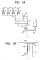
- Figs. 1A and 1B illustrate an example of the construction of a deposited-film formation apparatus according to the present invention.
- reference numeral 101 denotes a temperature sensor; 102, evacuation piping; 103, downstream-side evacuation piping; 104, a flange joint; 105, deposited-film-forming chamber; 106, a vacuum pump; 107, an exhaust gas treatment apparatus; 108, a high-frequency power source; 110, a gas introducing pipe; 111 to 114, gas flow meters; 115 to 118, valves; 119, electrodes; and 120, an aluminum tape.
- a thermocouple is used as the temperature sensor 101.
- the temperature sensor 101 is attached to the outer surface of the piping 103 in good contact so that the temperature of the evacuation piping 103 extending from the vacuum pump 106 to the exhaust gas treatment apparatus 107 can be measured.
- Deposited films are formed by means of this apparatus in the procedure as described below.
- the vacuum pump 106 is actuated to evacuate the inside of the chamber 105 to well remove any atmospheric components such as oxygen present in the chamber 105.
- valve 115 is opened to introduce into the chamber a dilute gas having been controlled at a desired flow rate through the gas flow meter 111.
- valves 116 and 117 are opened in the like procedure to introduce thereinto a material gas or gases and a doping gas.
- a desired high-frequency power which can well decompose the material gas or gases is applied by the high-frequency power source 108 to cause plasma (not shown) to form a deposited film on a substrate (not shown).
- any gas not decomposed by the high-frequency power is drawn out, as it is, to the vacuum pump 106 through the evacuation piping 102. Then, the gas is compressed and drawn out through the vacuum pump 106, which is thereafter led to the exhaust gas treatment apparatus 107.
- the gas is turned harmless and changed in quality into a stable state, which is then brought to disposal in a safe state.
- the high-frequency power source 108 is turned off to stop the formation of deposited film.
- valves 115 to 118 are opened or closed in the same procedure as the above to introduce into the chamber a gas or gases suited for the next deposited film, and a desired high-frequency power is again applied to form the deposited film.
- deposited films are further superposingly formed, the same procedure as the above may be repeated to form deposited films successively. Thereafter, the inside of the chamber 105 is well displaced with a purging gas (not shown), and then the vacuum pump 106 is stopped. On the substrate having the deposited films thus formed, for example a transparent conductive film is formed in the next step.
- the deposited films are formed in the above procedure.
- the material gases used to form the deposited films may contain at least one kind of gas reactive with atmosphere, such as spontaneously ignitable gas.
- Monosilane (SiH 4 ) and disilane (Si 2 H 6 ) are chief materials used when silicon films are formed, and are flowed at a high rate in the formation of deposited films and highly reactive with oxygen. Hence, monosilane (SiH 4 ) and disilane (Si 2 H 6 ) are particularly preferred when the leak is detected using the temperature sensor.
- monosilane (SiH 4 ), disilane (Si 2 H 6 ) or the like is used as the material gas.
- an element containing nitrogen atoms such as nitrogen (N 2 ) and ammonia (NH 3 ), oxygen (O 2 ), carbon monoxide (CO), carbon dioxide (CO 2 ), methane (CH 4 ), monogermane (GeH 4 ) or the like may also be added in order to change band gap width.
- a dopant gas such as diborane (B 2 H 6 ), boron trifluoride (BF 3 ) or phosphine (PH 3 ) may also simultaneously be introduced into the chamber for the purpose of doping.
- a gas reactive with atmosphere such as monogermane (GeH 4 ) or phosphine (PH 3 ) may be used as the dopant gas.
- thermocouple As the temperature sensor, a device which can effectively measure temperature of about room temperature is preferred. Also, a device which can well precisely measure temperature of about 0 to 150°C as exemplified by a thermocouple or a platinum resistance thermometer is more preferred. Depending on the part where the temperature is measured, a radiation type thermometer may also be used.
- thermocouple and a commonly available temperature indicator are used in combination
- the temperature indicator shows an abrupt rise in temperature upon any disconnection of the thermocouple, and hence there is a possibility that this is mistaken for the temperature rise due to a leak. Accordingly, in the case where the thermocouple and a commonly available temperature indicator are used in combination, any abrupt change in temperature within 10 to 30 seconds from the beginning of temperature rise may preferably be judged to be the disconnection of the thermocouple.
- thermocouples may also preferably be provided at one monitoring spot so that any temperature rise detected by a plurality of or all of thermocouples may be judged to be a leak. Also, a temperature rise detected by a plurality of thermocouples provided continuously in the direction of gas flow may also be judged to be a leak.
- leaks may also be judged by software processing using a computer.
- the occurrence of a leak may be judged using a program which can execute judgement of leaks or a computer-readable recording medium in which such a program has been recorded.
- the deposited-film formation apparatus or vacuum system may also have the above computer as a leak judgment means which judges the occurrence of a leak on the basis of a measured value of the temperature sensor. It may also have a feed-gas feed control means which stops the feeding of material gases upon detection of a leak by the leak judgment means.
- the occurrence of a leak may be judged, when done in a room, at 20°C to 50°C with respect to room temperature so as to prevent any miss-operation from being caused by any external disorder and also to ensure a good detection sensitivity.
- the temperature sensor may further be attached in the interior of piping. Such a case is effective for preventing miss-operation and improving detection sensitivity.
- the temperature sensor or the temperature sensor and the piping, may also be lagged with a heat insulator or the like so that the leak detection sensitivity does not lower even when part of the piping is provided outdoors and surrounding temperature may change greatly because of sunlight, wind and rain, atmospheric temperature and so forth.
- the temperature may also be monitored some frequently or always so that an average value of piping temperature can be found, and this value may be used as a reference value so that any variation from the reference value may be monitored. This brings about an improvement in detection precision. Also, a certain value of variation from a preset reference value may be set as a warning value so that any temperature changes due to seasonal variations can be taken into account. This brings about a more improvement in detection precision.
- the leak also tends to occur at piping connection flanges or at piping welded joints. Also, around the vacuum pump, the leak tends to occur because of any break of piping due to vibration or the like of the vacuum pump and because of any deterioration of O-rings due to oil mist.
- the temperature sensor may preferably be provided on the side downstream to such portions tending to cause a leak, bringing about an improvement in detection sensitivity. It may preferably be provided at a position about 5 to 20 cm downstream to the portion tending to cause a leak.
- Figs. 1A and 1B show an example of the deposited-film formation apparatus (vacuum system) (described previously) of the present invention.
- a thermocouple 101 was fixed as the temperature sensor 101 to the outer wall of a pipe attached directly to the vacuum pump 106 of the evacuation piping 103 extending between the vacuum pump 106 and the exhaust gas treatment apparatus 107.
- the temperature sensor (thermocouple) 101 was further covered with an aluminum tape 120 in order to more improve thermal contact.
- n-type layer At the time of formation of an n-type layer, fed were 250 ml/min ⁇ normal of monosilane (SiH 4 ), 3,000 ml/min ⁇ normal of hydrogen (H 2 ) and 20 ml/min ⁇ normal of phosphine (PH 3 ); at the time of formation of an i-type layer, 100 ml/min ⁇ normal of monosilane and 1,000 ml/min ⁇ normal of hydrogen; and at the time of formation of a p-type layer, 50 ml/min ⁇ normal of monosilane, 4,000 ml/min ⁇ normal of hydrogen and 2 ml/min ⁇ normal of boron trifluoride (BF 3 ).
- SiH 4 monosilane
- H 2 3,000 ml/min ⁇ normal of hydrogen
- PH 3 phosphine
- Example 1 amorphous silicon films were deposited on stainless steel substrates (not shown) in the manner as in the above embodiment, monitoring temperature indication of a temperature indicator (not shown) connected to the thermocouple 101.
- a temperature indicator (not shown) connected to the thermocouple 101.
- the deposited-film formation apparatus was continuously operated on and on, whereupon, in a certain batch, the temperature the thermocouple 101 kept to measure which was attached to the piping 103 extending between the vacuum pump 106 and the exhaust gas treatment apparatus 107 rose to 50°C from 30°C as shown in Fig. 2, in course of the formation of deposited films.
- Fig. 2 shows a change with deposition time lapsed, in the temperature the temperature sensor 101 indicates.
- the interior of the piping 103 was such that a by-product silicon oxide stood adhered only to the leaked portion and its vicinity, and hence it was immediately removable. Accordingly, the piping 103 having caused the leak was promptly exchanged. Also, all samples (deposited-film-formed substrates) were evaluated to find that samples on which deposited films were formed while the leak occurred showed faulty characteristics because of imperfect formation of deposited films, but samples obtained before the leak occurred did not show any lowering of characteristics.
- Fig. 3 shows an example of a conventional deposited-film formation apparatus (vacuum system).
- the same members or components as those in Figs. 1A and 1B are denoted by like reference numerals.
- Reference numeral 303 denotes evacuation piping.
- any temperature sensor 101 was not provided.
- fed were 250 ml/min ⁇ normal of monosilane (SiH 4 ), 3,000 ml/min ⁇ normal of hydrogen (H 2 ) and 20 ml/min ⁇ normal of phosphine (PH 3 ); at the time of formation of an i-type layer, 100 ml/min ⁇ normal of monosilane and 1,000 ml/min ⁇ normal of hydrogen; and at the time of formation of a p-type layer, 50 ml/min ⁇ normal of monosilane, 4,000 ml/min ⁇ normal of hydrogen and 2 ml/min ⁇ normal of boron trifluoride (BF 3 ).
- Comparative Example differs from Example 1 in that the piping temperature during the formation of deposited films was not monitored.
- Amorphous silicon films were deposited on stainless steel substrates in the manner as in the above embodiment. Deposited films formed by continuously operating the apparatus in this manner were evaluated as solar cells for each batch.
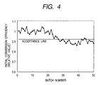
- Fig. 4 shows the relationship between batch number and initial conversion efficiency (relative value). As shown in Fig. 4, the conversion efficiency begins to lower at about batch number 23, and the lowering of characteristics is remarkable at about batch number 27 and the subsequent batches, where about 50% of the whole is seen to have low characteristics, resulting in defectives.
- silicon oxide which was a by-product of monosilane and oxygen had deposited and the silicon oxide had clogged the piping 303 by about 70% of its cross-sectional area. It took three days to remove this deposit. Also, with regard to unremovable portions, parts were replaced.
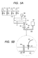
- Figs. 5A and 5B show another example of the construction of a deposited-film formation apparatus.
- Reference numeral 501 denotes a thermocouple; 503, evacuation piping; 504, a flange joint; and 521, a threaded joint.
- thermocouple 501 was fixed to evacuation piping 503 extending between the vacuum pump 106 and the exhaust gas treatment apparatus 107, at its position on 15 cm downstream side of the flange joint 504 of the piping and via the threaded joint 521.
- n-type layer At the time of formation of an n-type layer, fed were 250 ml/min ⁇ normal of monosilane (SiH 4 ), 3,000 ml/min ⁇ normal of hydrogen (H 2 ) and 20 ml/min ⁇ normal of phosphine (PH 3 ); at the time of formation of an i-type layer, 100 ml/min ⁇ normal of monosilane and 1,000 ml/min ⁇ normal of hydrogen; and at the time of formation of a p-type layer, 50 ml/min ⁇ normal of monosilane, 4,000 ml/min ⁇ normal of hydrogen and 2 ml/min ⁇ normal of boron trifluoride (BF 3 ).
- SiH 4 monosilane
- H 2 3,000 ml/min ⁇ normal of hydrogen
- PH 3 phosphine
- Example 2 amorphous silicon films were deposited on stainless steel substrates (not shown) in the manner as in the above embodiment, monitoring temperature indication of a temperature indicator (not shown) connected to the thermocouple 501.
- the deposited-film formation apparatus was continuously operated on and on, whereupon the temperature the thermocouple 501 kept to measure which was attached to the piping 503 extending between the vacuum pump 106 and the exhaust gas treatment apparatus 107 rose to 93°C from 31°C in course of the formation of deposited films.
- the formation of deposited films was immediately stopped to check the piping 503.
- the interior of the piping 503 was such that a by-product silicon oxide stood adhered only to the leaked portion and its vicinity, and hence it was immediately removable. The packing was also promptly exchanged. Also, all samples were evaluated to find that samples on which deposited films were formed while the leak occurred showed faulty characteristics because of imperfect formation of deposited films, but samples obtained before the leak occurred did not show any lowering of characteristics.
- Example 3 a deposited-film formation apparatus shown in Figs. 6A and 6B was used.
- Reference numeral 601 denotes a thermocouple; 603, evacuation piping; 622, a sight glass window; and 623, a heat insulator.
- the main part of the apparatus and the exhaust gas treatment apparatus 107 are provided at a large distance, and part of the evacuation piping 603, extending between the vacuum pump 106 and the exhaust gas treatment apparatus 107, is installed outdoors.
- This evacuation piping 603 is provided at its part exposed to the outdoor, with the sight glass window 622 so that its interior can be observed.
- the thermocouple 601 is provided at a position on 10 cm downstream side of the sight glass window 622. Also, the thermocouple 601 and its surrounding piping are kept covered with the heat insulator 623.
- Example 3 amorphous silicon films were deposited on stainless steel substrates (not shown) in the manner as in the above embodiment, monitoring temperature indication of a temperature indicator (not shown) connected to the thermocouple 601.
- the deposited-film formation apparatus was continuously operated on and on, whereupon, in a certain batch, the temperature the thermocouple 601 kept to measure which was attached to the piping 603 extending between the vacuum pump 106 and the exhaust gas treatment apparatus 107 rose to 24°C from 10°C in course of the formation of deposited films.
- the interior of the piping 603 was such that a by-product silicon oxide stood adhered only to the leaked portion and its vicinity, and hence it was immediately removable. Also, all samples were evaluated to find that samples on which deposited films were formed while the leak occurred showed faulty characteristics because of imperfect formation of deposited films, but samples obtained before the leak occurred did not show any lowering of characteristics.
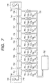
- Fig. 7 shows an example of a roll-to-roll type deposited-film formation apparatus (vacuum system) of the present invention.
- the apparatus shown in Fig. 7, usable for mass production of solar cells was used to continuously form amorphous silicon solar cells of n-i-p/n-i-p/n-i-p triple layer construction.
- thermocouples 701 to 709 denote thermocouples as temperature sensors; 711 to 719, evacuation piping; 720, main evacuation piping; 721 to 729, flexible tubes made of stainless steel; 730, a beltlike-substrate wind-off chamber; 741, slit-type passages; 731 to 739, deposited-film-forming chambers; 740, a beltlike-substrate wind-up chamber; 742, a beltlike-substrate; 751, vacuum pumps; and 752, an exhaust gas treatment apparatus.
- the thermocouples 701 to 709 are each provided at the part where each of the evacuation piping 711 to 719 is connected to the main evacuation piping 720.
- a deposited-film formation process is described with reference to Fig. 7.
- the insides of all the chambers 730 to 740 are brought to atmospheric pressure, and the insides of the chambers 730 to 740 are cleaned, where the beltlike substrate 742 wound in a roll is set in the substrate wind-off chamber 730.
- the roll-type substrate 742 is set by passing it through a plurality of deposited-film-forming chambers 731 to 739 and the slit-type passages 741 up to the substrate wind-up chamber 740.
- the insides of all the chambers 730 to 740 are evacuated by means of the vacuum pumps 751.
- the chambers 731 to 739 were heated by means of heaters (not shown) to effect baking sufficiently.
- fed from material gas feed piping were 250 ml/min ⁇ normal of monosilane (SiH 4 ), 3,000 ml/min ⁇ normal of hydrogen (H 2 ) and 20 ml/min ⁇ normal of phosphine (PH 3 ); at the time of formation of i-type layers, 100 ml/min ⁇ normal of monosilane and 1,000 ml/min ⁇ normal of hydrogen; and at the time of formation of p-type layers, 50 ml/min ⁇ normal of monosilane, 4,000 ml/min ⁇ normal of hydrogen and 2 ml/min ⁇ normal of boron trifluoride (BF 3 ).
- the material gases were thus fed and high-frequency power suited for the deposited-film-forming chambers 731 to 739 was supplied to form amorphous silicon solar cells of the triple layer construction, on the beltlike substrate 742 moving at a constant speed.
- thermocouple 705 In course of the formation of deposited films, the temperature measured with the thermocouple 705 rose to 78°C from 26°C. One minute later, the thermocouple 704 showed a temperature rise to 66°C from 26°C, and further one minute later, the thermocouple 703 a temperature rise to 51°C from 26°C. From this phenomenon, a leak was judged to have occurred at any of the flexible tube 725, the evacuation piping 715 and the main evacuation piping 720.
- the supply of high-frequency power, the feeding of material gases and the heaters which were heating the respective chambers were stopped, and, being kept evacuated, an inert gas helium (He) was continued to be fed through the respective chambers 730 to 740 to cool the deposited-film-forming chambers 731 to 739.
- an inert gas helium (He) was continued to be fed through the respective chambers 730 to 740 to cool the deposited-film-forming chambers 731 to 739.
- dry nitrogen was fed into the chambers 730 to 740 and the insides of the chambers 730 to 740 were returned to atmospheric pressure.
- the substrate wind-up chamber 740 was opened to take out a film-deposited beltlike substrate halfway wound up in a roll.
- the chambers 730 to 740 were again cleaned and a new beltlike substrate 742 wound in a roll was set in the substrate wind-off chamber 730 to continue film deposition under the like conditions.
- Fig. 8 shows the relationship between beltlike-substrate position in lengthwise direction and conversion efficiency.
- the flexible tube 725, the evacuation piping 715 and the main evacuation piping 720 which were considered to have caused a leak were checked to find that the leak has occurred at the stainless-steel flexible tube 725, provided on the evacuation piping 714 between the vacuum pump 751 and the main evacuation piping 720.
- the leak was presumed to be caused by an acid solution having stagnated in the flexible tube 725 and evacuation piping 715 and having corroded the stainless-steel flexible tube to make it brittle to cause a crack because of the vibration of the vacuum pump 751.
- the interior of the flexible tube 725 was such that a by-product silicon oxide stood adhered only to the leaked portion and its vicinity. Hence, the by-product was immediately removable and the tube was also promptly replaceable.
- the temperature sensor is provided on the chamber or at the evacuation piping, whereby any leak can be detected even when it occurs in the apparatus in course of the formation of deposited films.
- the detection is not affected at all by any condition inside the apparatus.
- the apparatus can also be set up at a low cost. In addition, because of a high reliability of leak detection, the apparatus can promptly be brought into a safe state.
- the present invention enables safe and stable formation of deposited films in a large quantity.
- a leak is detected on the basis of a measured value of a temperature sensor which detects the heat of reaction that is generated when the material gas fed into the chamber reacts with oxygen contained in air having entered from the outside, so as to be able to stop the material gas feeding.
- the leak can quickly be detected when air enters the chamber because of any unexpected accident such as a break of piping.
Landscapes
- Chemical & Material Sciences (AREA)
- Engineering & Computer Science (AREA)
- Physics & Mathematics (AREA)
- Chemical Kinetics & Catalysis (AREA)
- Analytical Chemistry (AREA)
- General Chemical & Material Sciences (AREA)
- Plasma & Fusion (AREA)
- Materials Engineering (AREA)
- Mechanical Engineering (AREA)
- Metallurgy (AREA)
- Organic Chemistry (AREA)
- General Physics & Mathematics (AREA)
- Chemical Vapour Deposition (AREA)
- Examining Or Testing Airtightness (AREA)
Abstract
Description
the deposited-film formation apparatus has a temperature sensor which detects the heat of reaction that is generated when the material gas fed into the chamber reacts with oxygen contained in air having entered from the outside of the deposited-film formation apparatus.
a leak is detected on the basis of a measured value of a temperature sensor which detects the heat of reaction that is generated when the material gas fed into the chamber reacts with oxygen contained in air having entered from the outside, so as to be able to stop the material gas feeding.
the deposited-film formation apparatus has at least one temperature sensor and a leak judgment means which judges the occurrence of a leak on the basis of a measured value of the temperature sensor.
the vacuum system has a temperature sensor which detects the heat of reaction that is generated when the material gas fed into the chamber reacts with oxygen contained in air having entered from the outside of the deposited-film formation apparatus.
the recorded program is a program for executing the step of totaling a plurality of measured values obtained by measuring temperature of the vacuum system at a plurality of spots thereof, and the step of judging the occurrence of a leak on the basis of a change with time of the plurality of measured values.
Claims (26)
- A deposited-film formation apparatus comprising:an inside-evacuatable chamber;a gas feed piping for feeding a material gas into the chamber;an evacuation means for evacuating the inside of the chamber;a first evacuation piping which connects the chamber and the evacuation means; anda second evacuation piping for guiding evacuation through the evacuation means, wherein,the deposited-film formation apparatus has a temperature sensor which detects the heat of reaction that is generated when the material gas fed into the chamber reacts with oxygen contained in air having entered from the outside of the deposited-film formation apparatus.
- The deposited-film formation apparatus according to claim 1, wherein the temperature sensor is provided on an outer wall surface of the chamber or at the evacuation piping.
- The deposited-film formation apparatus according to claim 1, wherein the temperature sensor is provided on the side downstream to the evacuation means.
- The deposited-film formation apparatus according to claim 1, wherein the first evacuation piping or the second evacuation piping has a piping connection part, and the temperature sensor is provided on the side downstream to the piping connection part.
- The deposited-film formation apparatus according to claim 1, which has a leak judgment means which judges the occurrence of a leak on the basis of a measured value of the temperature sensor, and a feed-gas feed control means which stops the feeding of material gases upon detection of a leak by the leak judgment means.
- The deposited-film formation apparatus according to claim 1, which has the chamber in plurality and a means for moving a beltlike member continuously through the insides of the chambers in their lengthwise direction.
- A deposited-film formation process comprising the steps of:evacuating the inside of an inside-evacuatable chamber through an evacuation piping by an evacuation means;feeding a material gas into the chamber while evacuating the inside of the chamber; andapplying a high-frequency power to form a deposited film on a substrate disposed inside the chamber, wherein,a leak is detected on the basis of a measured value of a temperature sensor which detects the heat of reaction that is generated when the material gas fed into the chamber reacts with oxygen contained in air having entered from the outside, so as to be able to stop the material gas feeding.
- The deposited-film formation process according to claim 7, wherein the leak is detected on the basis of an increase in a measured value of the temperature sensor.
- The deposited-film formation process according to claim 7, wherein the temperature sensor is provided on an outer wall surface of the chamber or at the evacuation piping.
- The deposited-film formation process according to claim 7, wherein the temperature sensor is provided on the side downstream to the evacuation means.
- The deposited-film formation process according to claim 7, wherein the evacuation piping has a piping connection part, and the temperature sensor is provided on the side downstream to the piping connection part.
- The deposited-film formation process according to claim 7, wherein the deposited film is formed on the substrate while the substrate is continuously moved in its lengthwise direction.
- A deposited-film formation apparatus comprising:a chamber;a gas feed piping for feeding a reactive material gas into the chamber; andan evacuation means and an evacuation piping by and through which the inside of the chamber is evacuated, wherein,the deposited-film formation apparatus has at least one temperature sensor and a leak judgment means which judges the occurrence of a leak on the basis of a measured value of the temperature sensor.
- The deposited-film formation apparatus according to claim 13, wherein the temperature sensor is provided in plurality, and the leak judgment means judges the leak to have occurred when the measured values of the temperature sensor provided in plurality increase.
- The deposited-film formation apparatus according to claim 14, wherein the temperature sensors are provided along the flow of gas, and the leak judgment means judges the leak to have occurred when the measured values of the temperature sensors increase along the flow of gas.
- A vacuum system comprising:a chamber;a gas feed means for feeding a gas into the chamber; andan evacuation means and an evacuation piping by and through which the inside of the chamber is evacuated, wherein,the vacuum system has a temperature sensor which detects the heat of reaction that is generated when the material gas fed into the chamber reacts with oxygen contained in air having entered from the outside of the deposited-film formation apparatus.
- A leak judgment method comprising the steps of:feeding a reactive gas to the inside of a vacuum system having a chamber and an evacuation piping;measuring temperature of the vacuum system at a plurality of spots thereof; andjudging the occurrence of a leak on the basis of a change with time of a plurality of measured values obtained by measuring the temperature.
- The leak judgment method according to claim 17, wherein the leak is judged to have occurred when the plurality of measured values increase.
- The leak judgment method according to claim 17, wherein the temperature of the vacuum system is measured at a plurality of spots thereof along the flow of gas in the vacuum system, and the leak is judged to have occurred when the plurality of measured values obtained by measuring the temperature increase along the flow of gas.
- The leak judgment method according to claim 17, wherein an average value of the temperature of the evacuation piping is found to regard it as a reference value, and the occurrence of a leak of the vacuum system is judged on the basis of a change with time with respect to the reference value, in the plurality of measured values.
- The leak judgment method according to claim 20, wherein a value greater than the reference value is set as a warning value in advance, and the leak is judged to have occurred when the plurality of measured values become greater than the warning value.
- A computer-readable recording medium with a recorded program which is able to execute judgment on the occurrence of a leak of a vacuum system having a chamber into which a reactive gas is to be fed and having an evacuation piping, wherein,
the recorded program is a program for executing the step of totaling a plurality of measured values obtained by measuring temperature of the vacuum system at a plurality of spots thereof, and the step of judging the occurrence of a leak on the basis of a change with time of the plurality of measured values. - The computer-readable recording medium with a recorded program according to claim 22, which judges the leak to have occurred when the plurality of measured values increase.
- The computer-readable recording medium with a recorded program according to claim 22, which judges the leak to have occurred when the plurality of measured values increase along the flow of gas.
- The computer-readable recording medium with a recorded program according to claim 22, wherein the recorded program is a program for executing the step of finding an average value of the temperature of the evacuation piping to regard it as a reference value, and the step of judging the occurrence of a leak of the vacuum system on the basis of a change with time with respect to the reference value, in the plurality of measured values.
- The computer-readable recording medium with a recorded program according to claim 25, wherein the recorded program is a program for executing the step of setting a value greater than the reference value as a warning value in advance, and the step of comparing the plurality of measured values with the warning value to judge the leak to have occurred when the plurality of measured values become greater than the warning value.
Applications Claiming Priority (2)
| Application Number | Priority Date | Filing Date | Title |
|---|---|---|---|
| JP2000131772 | 2000-04-28 | ||
| JP2000131772 | 2000-04-28 |
Publications (2)
| Publication Number | Publication Date |
|---|---|
| EP1150328A2 true EP1150328A2 (en) | 2001-10-31 |
| EP1150328A3 EP1150328A3 (en) | 2005-01-05 |
Family
ID=18640605
Family Applications (1)
| Application Number | Title | Priority Date | Filing Date |
|---|---|---|---|
| EP01110383A Withdrawn EP1150328A3 (en) | 2000-04-28 | 2001-04-26 | Vacuum system for film formation apparatus and process, leak judgement method, and computer-readable recording medium with recorded leak-judgment-executable program |
Country Status (3)
| Country | Link |
|---|---|
| US (2) | US20030207021A1 (en) |
| EP (1) | EP1150328A3 (en) |
| CN (1) | CN1291062C (en) |
Cited By (1)
| Publication number | Priority date | Publication date | Assignee | Title |
|---|---|---|---|---|
| CN106932431A (en) * | 2015-12-29 | 2017-07-07 | 北京有色金属研究总院 | A kind of online heat waste test system of slot type high-temperature vacuum heat-collecting tube and method |
Families Citing this family (14)
| Publication number | Priority date | Publication date | Assignee | Title |
|---|---|---|---|---|
| US20030207021A1 (en) * | 2000-04-28 | 2003-11-06 | Hiroshi Izawa | Deposited-film formation apparatus, deposited-film formation process, vacuum system, leak judgment method, and computer-readable recording medium with recorded leak-judgment- executable program |
| KR100863782B1 (en) * | 2002-03-08 | 2008-10-16 | 도쿄엘렉트론가부시키가이샤 | Substrate Processing Apparatus and Substrate Processing Method |
| US8288719B1 (en) * | 2006-12-29 | 2012-10-16 | Griffin Analytical Technologies, Llc | Analytical instruments, assemblies, and methods |
| US8205484B2 (en) * | 2009-02-17 | 2012-06-26 | Fukuda Co., Ltd. | Apparatus and method for leak testing |
| US8167484B2 (en) * | 2009-04-29 | 2012-05-01 | Solex High-Tech Co., Ltd. | Temperature indication pipe joint |
| KR20130112627A (en) * | 2012-04-04 | 2013-10-14 | 동부대우전자 주식회사 | Abnormal detecting apparatus and method of cooling cycle for refrigerator |
| US10269601B2 (en) * | 2015-10-20 | 2019-04-23 | Applied Materials, Inc. | Chamber leak and gas contaimination detection |
| JP6924775B2 (en) * | 2016-04-26 | 2021-08-25 | アプライド マテリアルズ インコーポレイテッドApplied Materials,Incorporated | Temperature-controlled remote plasma cleaning for removal of exhaust deposits |
| CN109781049A (en) * | 2019-01-22 | 2019-05-21 | 上海华虹宏力半导体制造有限公司 | The monitoring method of pollutant in ion injection machine table reaction chamber |
| KR102868514B1 (en) * | 2019-11-04 | 2025-10-02 | 허니웰 인터내셔널 인코포레이티드 | Method and system for detecting a false alarm event in gas detection |
| WO2021229787A1 (en) * | 2020-05-15 | 2021-11-18 | 株式会社日立ハイテク | Plasma processing apparatus inspection method |
| CN112572846A (en) * | 2020-11-23 | 2021-03-30 | 蓝箭航天技术有限公司 | Ignition device test method and system |
| CN113063547B (en) * | 2021-03-22 | 2021-12-07 | 攀钢集团攀枝花钢钒有限公司 | RH furnace vacuum system leakage searching method |
| US20250314549A1 (en) * | 2024-04-08 | 2025-10-09 | Edison Welding Institute, Inc. | Colorimetric gas leak detection |
Family Cites Families (35)
| Publication number | Priority date | Publication date | Assignee | Title |
|---|---|---|---|---|
| JPS50388B1 (en) * | 1970-05-12 | 1975-01-08 | ||
| US4356825A (en) * | 1978-08-21 | 1982-11-02 | United States Surgical Corporation | Method and system for measuring rate of occurrence of a physiological parameter |
| US4357113A (en) * | 1980-05-14 | 1982-11-02 | Brooks Wahner E | Liquid container leakage detection method and system |
| US4409817A (en) * | 1981-03-25 | 1983-10-18 | Edwards Jr David | Vacuum leak detector and method |
| US4602872A (en) * | 1985-02-05 | 1986-07-29 | Westinghouse Electric Corp. | Temperature monitoring system for an electric generator |
| US4791805A (en) * | 1985-06-07 | 1988-12-20 | Expertek, Inc. | Fuel tank leak detection apparatus |
| US4969749A (en) * | 1988-11-10 | 1990-11-13 | Hasselmann Detlev E M | Apparatus and method for measurement of average temperature change in a storage tank |
| JP2952894B2 (en) * | 1989-07-03 | 1999-09-27 | 富士通株式会社 | Vacuum apparatus and gas analysis method in process chamber |
| US5127365A (en) * | 1990-02-27 | 1992-07-07 | Kabushiki Kaisha Toshiba | Vertical heat-treatment apparatus for semiconductor parts |
| US5522957A (en) * | 1993-12-22 | 1996-06-04 | Vlsi Technology, Inc. | Method for leak detection in etching chambers |
| JPH08105812A (en) * | 1994-06-08 | 1996-04-23 | Takaoka Electric Mfg Co Ltd | Gas leak monitoring device for gas-insulated electrical equipment |
| JP3982844B2 (en) * | 1995-01-12 | 2007-09-26 | 株式会社日立国際電気 | Semiconductor manufacturing apparatus and semiconductor manufacturing method |
| US6273955B1 (en) | 1995-08-28 | 2001-08-14 | Canon Kabushiki Kaisha | Film forming apparatus |
| JP3591977B2 (en) * | 1996-03-18 | 2004-11-24 | キヤノン株式会社 | Film deposition method and film deposition apparatus using microwave plasma CVD |
| DE69732038T2 (en) * | 1996-07-18 | 2005-11-03 | Kao Corp. | FILLERS FOR PAPER |
| JP3748473B2 (en) * | 1996-12-12 | 2006-02-22 | キヤノン株式会社 | Deposited film forming equipment |
| JP4022954B2 (en) | 1997-01-29 | 2007-12-19 | ソニー株式会社 | COMPOSITE MATERIAL AND ITS MANUFACTURING METHOD, SUBSTRATE TREATING APPARATUS AND ITS MANUFACTURING METHOD, SUBSTRATE MOUNTING STAGE AND ITS MANUFACTURING METHOD, AND SUBSTRATE TREATING METHOD |
| US5979225A (en) * | 1997-08-26 | 1999-11-09 | Applied Materials, Inc. | Diagnosis process of vacuum failure in a vacuum chamber |
| US7194893B2 (en) * | 1997-10-02 | 2007-03-27 | Siemens Canada Limited | Temperature correction method and subsystem for automotive evaporative leak detection systems |
| DK0932034T3 (en) * | 1998-01-27 | 2004-10-04 | Michael Hesky Gmbh | Temperature measuring and monitoring device |
| JPH11345778A (en) * | 1998-05-29 | 1999-12-14 | Tokyo Electron Ltd | Method of cleaning film forming apparatus and cleaning mechanism thereof |
| CN1260599A (en) | 1998-12-22 | 2000-07-19 | 佳能株式会社 | Apparatus for treating backing and method thereof |
| US6286992B1 (en) * | 1999-02-12 | 2001-09-11 | Meritor Heavy Vehicle Systems, Llc | Axle temperature monitor |
| JP2000256856A (en) * | 1999-03-11 | 2000-09-19 | Tokyo Electron Ltd | Processing apparatus, vacuum exhaust system for processing apparatus, reduced pressure CVD apparatus, vacuum exhaust system for reduced pressure CVD apparatus, and trap apparatus |
| US6155289A (en) * | 1999-05-07 | 2000-12-05 | International Business Machines | Method of and system for sub-atmospheric gas delivery with backflow control |
| US20030207021A1 (en) * | 2000-04-28 | 2003-11-06 | Hiroshi Izawa | Deposited-film formation apparatus, deposited-film formation process, vacuum system, leak judgment method, and computer-readable recording medium with recorded leak-judgment- executable program |
| JP3594235B2 (en) * | 2000-05-22 | 2004-11-24 | インターナショナル・ビジネス・マシーンズ・コーポレーション | Heat treatment furnace with gas leakage prevention function |
| US7001640B2 (en) * | 2000-05-31 | 2006-02-21 | Canon Kabushiki Kaisha | Apparatus and method for forming deposited film |
| US6354140B1 (en) * | 2000-09-18 | 2002-03-12 | The Boeing Company | Fluid leakage detector for vacuum applications |
| JP2002350925A (en) * | 2001-05-30 | 2002-12-04 | Fuji Photo Film Co Ltd | Diaphragm switching device for camera |
| WO2003027587A1 (en) * | 2001-09-19 | 2003-04-03 | Kabushiki Kaisha Toshiba | Refrigerator-freezer, controller of refrigerator-freezer, and method for determination of leakage of refrigerant |
| EP1394835A1 (en) * | 2002-08-29 | 2004-03-03 | STMicroelectronics S.r.l. | A method and apparatus for detecting a leak of external air into a plasma reactor |
| TW577124B (en) * | 2002-12-03 | 2004-02-21 | Mosel Vitelic Inc | Method for estimating the forming thickness of the oxide layer and determining whether the pipes occur leakages |
| JP5063340B2 (en) * | 2005-02-18 | 2012-10-31 | パナソニック株式会社 | Fuel cell system and operation method thereof |
| KR100816453B1 (en) * | 2006-06-28 | 2008-03-27 | (주)쎄미시스코 | Real-time leak detection system of process chamber |
-
2001
- 2001-04-19 US US09/837,459 patent/US20030207021A1/en not_active Abandoned
- 2001-04-26 EP EP01110383A patent/EP1150328A3/en not_active Withdrawn
- 2001-04-28 CN CNB01117434XA patent/CN1291062C/en not_active Expired - Fee Related
-
2005
- 2005-11-10 US US11/270,563 patent/US7641382B2/en not_active Expired - Fee Related
Cited By (1)
| Publication number | Priority date | Publication date | Assignee | Title |
|---|---|---|---|---|
| CN106932431A (en) * | 2015-12-29 | 2017-07-07 | 北京有色金属研究总院 | A kind of online heat waste test system of slot type high-temperature vacuum heat-collecting tube and method |
Also Published As
| Publication number | Publication date |
|---|---|
| US20030207021A1 (en) | 2003-11-06 |
| CN1291062C (en) | 2006-12-20 |
| EP1150328A3 (en) | 2005-01-05 |
| US7641382B2 (en) | 2010-01-05 |
| CN1323917A (en) | 2001-11-28 |
| US20060068081A1 (en) | 2006-03-30 |
Similar Documents
| Publication | Publication Date | Title |
|---|---|---|
| US7641382B2 (en) | Leak judgment method, and computer-readable recording medium with recorded leak-judgment-executable program | |
| KR100391872B1 (en) | Moisture monitoring apparatus and semiconductor manufacturing apparatus having same | |
| KR100260957B1 (en) | A thin plate-shaped substrate transfer method and transfer device | |
| US10663336B2 (en) | Processing chamber gas detection system and operation method thereof | |
| US8384902B2 (en) | Optical gas-analysis system and a gas flow cell | |
| JP3895326B2 (en) | Control of thermal oxidation process by controlling partial pressure of oxidant | |
| WO2004036173A2 (en) | Fourier transform infrared (ftir) spectrometric toxic gas monitoring system and method | |
| US12259297B2 (en) | Method for box leak detection and leak detection system | |
| CN119685807A (en) | Calibration method of mass flow controller and chemical vapor deposition machine | |
| KR100572700B1 (en) | A method and apparatus for detecting a vacuum leakage | |
| JP2002012974A (en) | Deposited film forming apparatus, deposited film forming method, vacuum apparatus, leak determination method, and program capable of executing leak determination | |
| JP3289190B2 (en) | Semiconductor process gas supply system | |
| TWI636253B (en) | Measuring device using spectrometer to measure gas dissociation state | |
| CN113113332A (en) | Method for detecting leakage of semiconductor process cavity | |
| US6699603B1 (en) | Stainless steel having passive fluoride film formed thereon and equipment manufactured therefrom | |
| Sarver-Verhey | Extended testing of xenon ion thruster hollow cathodes | |
| JPH11204511A (en) | Silicon thermal oxide film forming equipment | |
| JP3413711B2 (en) | Gas leak detection system | |
| US7001640B2 (en) | Apparatus and method for forming deposited film | |
| KR200489281Y1 (en) | Contamination sensor for process gas line | |
| CN220602634U (en) | Flame arrester ventilation experimental device | |
| US20250123174A1 (en) | Thermocouple leak detection | |
| JP2003115516A (en) | Wafer for moisture measurement, method for calibrating moisture meter, and method for evaluating condition of heat treatment furnace | |
| JP2019099871A (en) | Leak detection method of deposition film forming device and deposition film forming method | |
| JP2008266711A (en) | Vacuum deposition equipment |
Legal Events
| Date | Code | Title | Description |
|---|---|---|---|
| PUAI | Public reference made under article 153(3) epc to a published international application that has entered the european phase |
Free format text: ORIGINAL CODE: 0009012 |
|
| AK | Designated contracting states |
Kind code of ref document: A2 Designated state(s): AT BE CH CY DE DK ES FI FR GB GR IE IT LI LU MC NL PT SE TR |
|
| AX | Request for extension of the european patent |
Free format text: AL;LT;LV;MK;RO;SI |
|
| PUAL | Search report despatched |
Free format text: ORIGINAL CODE: 0009013 |
|
| AK | Designated contracting states |
Kind code of ref document: A3 Designated state(s): AT BE CH CY DE DK ES FI FR GB GR IE IT LI LU MC NL PT SE TR |
|
| AX | Request for extension of the european patent |
Extension state: AL LT LV MK RO SI |
|
| AKX | Designation fees paid |
Designated state(s): DE FR GB IT NL |
|
| STAA | Information on the status of an ep patent application or granted ep patent |
Free format text: STATUS: THE APPLICATION IS DEEMED TO BE WITHDRAWN |
|
| 18D | Application deemed to be withdrawn |
Effective date: 20050706 |