JP6924775B2 - Temperature-controlled remote plasma cleaning for removal of exhaust deposits - Google Patents
Temperature-controlled remote plasma cleaning for removal of exhaust deposits Download PDFInfo
- Publication number
- JP6924775B2 JP6924775B2 JP2018555590A JP2018555590A JP6924775B2 JP 6924775 B2 JP6924775 B2 JP 6924775B2 JP 2018555590 A JP2018555590 A JP 2018555590A JP 2018555590 A JP2018555590 A JP 2018555590A JP 6924775 B2 JP6924775 B2 JP 6924775B2
- Authority
- JP
- Japan
- Prior art keywords
- exhaust system
- temperature
- downstream
- remote plasma
- cleaning gas
- Prior art date
- Legal status (The legal status is an assumption and is not a legal conclusion. Google has not performed a legal analysis and makes no representation as to the accuracy of the status listed.)
- Active
Links
Images

Classifications
-
- B—PERFORMING OPERATIONS; TRANSPORTING
- B08—CLEANING
- B08B—CLEANING IN GENERAL; PREVENTION OF FOULING IN GENERAL
- B08B7/00—Cleaning by methods not provided for in a single other subclass or a single group in this subclass
- B08B7/0035—Cleaning by methods not provided for in a single other subclass or a single group in this subclass by radiant energy, e.g. UV, laser, light beam or the like
-
- B—PERFORMING OPERATIONS; TRANSPORTING
- B01—PHYSICAL OR CHEMICAL PROCESSES OR APPARATUS IN GENERAL
- B01D—SEPARATION
- B01D53/00—Separation of gases or vapours; Recovering vapours of volatile solvents from gases; Chemical or biological purification of waste gases, e.g. engine exhaust gases, smoke, fumes, flue gases, aerosols
- B01D53/32—Separation of gases or vapours; Recovering vapours of volatile solvents from gases; Chemical or biological purification of waste gases, e.g. engine exhaust gases, smoke, fumes, flue gases, aerosols by electrical effects other than those provided for in group B01D61/00
-
- C—CHEMISTRY; METALLURGY
- C30—CRYSTAL GROWTH
- C30B—SINGLE-CRYSTAL GROWTH; UNIDIRECTIONAL SOLIDIFICATION OF EUTECTIC MATERIAL OR UNIDIRECTIONAL DEMIXING OF EUTECTOID MATERIAL; REFINING BY ZONE-MELTING OF MATERIAL; PRODUCTION OF A HOMOGENEOUS POLYCRYSTALLINE MATERIAL WITH DEFINED STRUCTURE; SINGLE CRYSTALS OR HOMOGENEOUS POLYCRYSTALLINE MATERIAL WITH DEFINED STRUCTURE; AFTER-TREATMENT OF SINGLE CRYSTALS OR A HOMOGENEOUS POLYCRYSTALLINE MATERIAL WITH DEFINED STRUCTURE; APPARATUS THEREFOR
- C30B25/00—Single-crystal growth by chemical reaction of reactive gases, e.g. chemical vapour-deposition growth
- C30B25/02—Epitaxial-layer growth
- C30B25/14—Feed and outlet means for the gases; Modifying the flow of the reactive gases
-
- C—CHEMISTRY; METALLURGY
- C30—CRYSTAL GROWTH
- C30B—SINGLE-CRYSTAL GROWTH; UNIDIRECTIONAL SOLIDIFICATION OF EUTECTIC MATERIAL OR UNIDIRECTIONAL DEMIXING OF EUTECTOID MATERIAL; REFINING BY ZONE-MELTING OF MATERIAL; PRODUCTION OF A HOMOGENEOUS POLYCRYSTALLINE MATERIAL WITH DEFINED STRUCTURE; SINGLE CRYSTALS OR HOMOGENEOUS POLYCRYSTALLINE MATERIAL WITH DEFINED STRUCTURE; AFTER-TREATMENT OF SINGLE CRYSTALS OR A HOMOGENEOUS POLYCRYSTALLINE MATERIAL WITH DEFINED STRUCTURE; APPARATUS THEREFOR
- C30B29/00—Single crystals or homogeneous polycrystalline material with defined structure characterised by the material or by their shape
- C30B29/02—Elements
- C30B29/06—Silicon
-
- H—ELECTRICITY
- H01—ELECTRIC ELEMENTS
- H01J—ELECTRIC DISCHARGE TUBES OR DISCHARGE LAMPS
- H01J37/00—Discharge tubes with provision for introducing objects or material to be exposed to the discharge, e.g. for the purpose of examination or processing thereof
- H01J37/32—Gas-filled discharge tubes
- H01J37/32009—Arrangements for generation of plasma specially adapted for examination or treatment of objects, e.g. plasma sources
- H01J37/32357—Generation remote from the workpiece, e.g. down-stream
-
- H—ELECTRICITY
- H01—ELECTRIC ELEMENTS
- H01J—ELECTRIC DISCHARGE TUBES OR DISCHARGE LAMPS
- H01J37/00—Discharge tubes with provision for introducing objects or material to be exposed to the discharge, e.g. for the purpose of examination or processing thereof
- H01J37/32—Gas-filled discharge tubes
- H01J37/32431—Constructional details of the reactor
- H01J37/32798—Further details of plasma apparatus not provided for in groups H01J37/3244 - H01J37/32788; special provisions for cleaning or maintenance of the apparatus
- H01J37/32816—Pressure
- H01J37/32834—Exhausting
-
- H—ELECTRICITY
- H01—ELECTRIC ELEMENTS
- H01J—ELECTRIC DISCHARGE TUBES OR DISCHARGE LAMPS
- H01J37/00—Discharge tubes with provision for introducing objects or material to be exposed to the discharge, e.g. for the purpose of examination or processing thereof
- H01J37/32—Gas-filled discharge tubes
- H01J37/32917—Plasma diagnostics
- H01J37/32935—Monitoring and controlling tubes by information coming from the object and/or discharge
- H01J37/32963—End-point detection
-
- B—PERFORMING OPERATIONS; TRANSPORTING
- B01—PHYSICAL OR CHEMICAL PROCESSES OR APPARATUS IN GENERAL
- B01D—SEPARATION
- B01D2259/00—Type of treatment
- B01D2259/80—Employing electric, magnetic, electromagnetic or wave energy, or particle radiation
- B01D2259/818—Employing electrical discharges or the generation of a plasma
-
- H—ELECTRICITY
- H01—ELECTRIC ELEMENTS
- H01J—ELECTRIC DISCHARGE TUBES OR DISCHARGE LAMPS
- H01J2237/00—Discharge tubes exposing object to beam, e.g. for analysis treatment, etching, imaging
- H01J2237/32—Processing objects by plasma generation
- H01J2237/33—Processing objects by plasma generation characterised by the type of processing
- H01J2237/335—Cleaning
Description
本開示の態様は概して、エピタキシャルシリコンを形成するためのプロセスチャンバと共に使用される排気システムといった排気システムを洗浄するための、方法及び装置に関する。 Aspects of the present disclosure generally relate to methods and equipment for cleaning an exhaust system, such as an exhaust system used with a process chamber for forming epitaxial silicon.
関連技術の説明
エピタキシャルシリコンは、ケイ素含有前駆体ガスを使用して、プロセスチャンバ内で堆積される。プロセスチャンバ内での所定の回数の堆積サイクルの後に、プロセスチャンバは、塩素含有ガスを使用して洗浄される。塩素含有ガスからの塩素ラジカルは、ケイ素と反応してクロロシランを形成し、このクロロシランはプロセスチャンバから排気される。クロロシランは、排気システムの内表面に堆積する可燃性物質であり、定期的に除去される必要がある。クロロシランを除去するための洗浄時間は、必要とされる除去の度合いに応じて、半日から最大1か月までの期間にわたりうる。加えて、クロロシランは、排気システムの解体時に周囲環境の酸素と反応することによって、接触爆発性のクロロシロキサンを形成しうる。クロロシロキサンの形成により、担当者が一層の注意を払うことになるため、洗浄及びメンテナンスに必要な時間は更に長くなる。
Description of Related Techniques Epitaxial silicon is deposited in a process chamber using a silicon-containing precursor gas. After a predetermined number of deposition cycles in the process chamber, the process chamber is cleaned with chlorine-containing gas. Chlorine radicals from the chlorine-containing gas react with silicon to form chlorosilane, which is exhausted from the process chamber. Chlorosilane is a flammable substance that deposits on the inner surface of the exhaust system and needs to be removed on a regular basis. The wash time to remove chlorosilane can range from half a day to a maximum of one month, depending on the degree of removal required. In addition, chlorosilane can form contact-explosive chlorosiloxanes by reacting with oxygen in the ambient environment when the exhaust system is dismantled. The formation of chlorosiloxane requires the person in charge to pay more attention, which further increases the time required for cleaning and maintenance.
したがって、排気システムを洗浄するための、改良型の方法及び装置が必要とされている。 Therefore, there is a need for improved methods and equipment for cleaning the exhaust system.
一態様では、処理システムは、プロセスチャンバと、プロセスチャンバに連結された排気システムとを備える。排気システムは、プロセスチャンバの下流で排気システムにイオン化洗浄ガスを供給するための、遠隔プラズマ源と、排気システムの一又は複数の場所において排気システムの温度を測定するための、一又は複数のセンサとを備える。 In one aspect, the processing system comprises a process chamber and an exhaust system connected to the process chamber. The exhaust system is a remote plasma source for supplying ionized cleaning gas to the exhaust system downstream of the process chamber and one or more sensors for measuring the temperature of the exhaust system at one or more locations in the exhaust system. And.
別の態様では、処理システムは、プロセスチャンバと、プロセスチャンバに連結された排気システムとを備える。排気システムは、プロセスチャンバの下流で排気システムにイオン化洗浄ガスを供給するための、遠隔プラズマ源と、排気システムの一又は複数の場所において排気システムの温度を測定するための、遠隔プラズマ源の下流にある一又は複数のセンサと、一又は複数のセンサの下流にある終点検出システムと、終点検出システムの下流にある真空ポンプとを、備える。 In another aspect, the processing system comprises a process chamber and an exhaust system connected to the process chamber. The exhaust system is a remote plasma source for supplying ionized cleaning gas to the exhaust system downstream of the process chamber and downstream of the remote plasma source for measuring the temperature of the exhaust system at one or more locations in the exhaust system. It comprises one or more sensors in, an end point detection system downstream of one or more sensors, and a vacuum pump downstream of the end point detection system.
別の実施形態では、排気システムを洗浄するためのプロセスは、プロセスチャンバの下流で排気システムに一又は複数のイオン化ガスを導入することと、排気システムの中の温度をモニタすることと、モニタされた温度に基づいて、一又は複数のイオン化ガスの流量を調整することとを、含む。 In another embodiment, the process for cleaning the exhaust system is monitored by introducing one or more ionized gases into the exhaust system downstream of the process chamber and monitoring the temperature inside the exhaust system. It includes adjusting the flow rate of one or more ionized gases based on the temperature.
本開示の上述の特徴を詳しく理解しうるように、上記で簡単に要約した本開示のより詳細な説明が、態様を参照することによって得られる。一部の態様は、付随する図面に示されている。しかし、付随する図面は例示的な態様のみを示すものであり、したがって、本開示の範囲を限定すると見なすべきではなく、本開示は他の等しく有効な態様も許容しうることに、留意されたい。 A more detailed description of the present disclosure, briefly summarized above, is obtained by reference to aspects so that the above-mentioned features of the present disclosure can be understood in detail. Some aspects are shown in the accompanying drawings. However, it should be noted that the accompanying drawings show only exemplary embodiments and should therefore not be considered limiting the scope of the present disclosure, and the present disclosure may tolerate other equally valid embodiments. ..
理解を容易にするために、可能な場合には、複数の図に共通する同一の要素を指し示すのに同一の参照番号を使用した。一態様の要素及び特徴は、更なる記述がなくとも、他の態様に有益に組み込まれうると想定される。 For ease of understanding, the same reference numbers were used to point to the same elements that are common to multiple figures, where possible. It is assumed that the elements and features of one aspect can be beneficially incorporated into another aspect without further description.
本開示の態様は概して、エピタキシャルシリコンを形成するためのプロセスチャンバと共に使用される排気システムといった排気システムを洗浄するための、方法及び装置に関する。排気システムは、排気システムを通るイオン化ガスを供給するための遠隔プラズマ源と、遠隔プラズマ源の下流に配置された一又は複数の温度センサとを含む。本書に記載の方法及び装置の使用は、その他のエッチングなどのプロセス、又は、エピタキシャルシリコン以外の物質の堆積のためのものでもあると想定されることに、留意されたい。 Aspects of the present disclosure generally relate to methods and equipment for cleaning an exhaust system, such as an exhaust system used with a process chamber for forming epitaxial silicon. The exhaust system includes a remote plasma source for supplying ionized gas through the exhaust system and one or more temperature sensors located downstream of the remote plasma source. It should be noted that the use of the methods and equipment described herein is also assumed to be for other processes such as etching or for the deposition of substances other than epitaxial silicon.
図1は、本開示の一態様による処理システム100の概略図である。処理システム100は、排気システム102に連結されたプロセスチャンバ101(エピタキシャル堆積リアクタなど)を含む。排気システム102は、排気システム102の下流に配置されたスクラバー122に排出物を流すことを容易にするために、排気システム102の下流側端部で真空ポンプ103に連結される。排気システム102は、ベローズ105を介して排気システム102に連結された、終点検出システム104を含みうる。排気システム102及びベローズ105は、洗浄工程の終点の判定を容易にするために、真空ポンプ103の上流に配置されうる。
FIG. 1 is a schematic view of a
洗浄ガス、パージガス、キャリアガス、又はその他のプロセスガスをイオン化するため、及び、排気システム102にイオン化ガスを提供するために、遠隔プラズマ源(RPS)106が、排気システム102に連結される。例えば、アルゴンなどの不活性ガス又は非反応性ガスを提供するために、第1ガス供給源107が、RPS106に、そしてこれを通じて排気システム102に、連結されうる。加えて、NF3などの洗浄ガスを提供するために、第2ガス供給源108が、RPS106に、そしてこれを通じて排気システム102に、連結されうる。これ以外の想定される洗浄ガスは、NF2H、CHF3、CF4などを含む。その他の洗浄ガス及び非反応性ガスも想定されることに、留意されたい。イオン化ガスにより、排気システム102の内部からの蓄積堆積物の除去が容易になり、ひいては、洗浄のために排気システム102を解体する必要性が減少するか、又はなくなる。
A remote plasma source (RPS) 106 is coupled to the
排気システム102は、プロセスチャンバ101内への排気の逆流を防止する、第1分離バルブ109を含む。プロセスチャンバ101は、壁120によって真空ポンプ103から分離されうる。RPS106は、ガス通路110を介して、第1分離バルブ109の下流で排気システム102に連結される。ガス通路110は、ガス通路110を通るガス流を制御するための、ひいては、RPS106から排気システム102へのガス流を制御するための、ガス通路110に配置された第2分離バルブ111を含む。分離バルブ109及び111は、コントローラ(図示せず)によって制御されうる。
The
排気システム102は、温度を検知するための一又は複数のセンサ112a〜112g(7つを図示している)も含む。第1温度センサ112aは、分離バルブ109及び111の下流の、圧力制御バルブ113の上流に配置されている。残りのセンサ112b〜112gは、圧力制御バルブ113の下流の、ベローズ105の上流に配置されている。センサ112a〜112gにより、排気システム102の種々の場所における排気温度のモニタリングが容易になる。一態様では、センサ112a〜112gは、排気システム102内の排出物質の堆積が増大しやすい場所に配置される。例えば、バルブ、肘状部、T型部品などでは、物質の堆積が増大しやすい。一例では、センサ112a〜112gは熱電対でありうる。一例では、温度センサ112e及び112fは床121の下に配置される。
The
温度センサ112a〜112gにより、排気システム102における洗浄工程のモニタリングが容易になる。洗浄ガスからのフッ素ラジカルとクロロシラン堆積物との反応は、発熱性である。ゆえに、温度測定を通じて、反応の度合いが概括的に認定されうる。例えば、排気システム102内の温度を追跡することによって、洗浄工程の終点検出がモニタされうる。センサ112a〜112gにおいて高温であることは、洗浄ガスと堆積物質とが反応していることを示す一方、温度が、周囲温度(又は、RPS106から出る洗浄ガスの温度)とほぼ等しいこと、又はかかる温度に接近していることは、反応/堆積物質の除去が完了したことにより、洗浄工程が実質的に完了したことを示す。
The
追加的又は代替的には、センサ112a〜112gは、洗浄工程のモニタリング及び制御を容易にするために利用されうる。例えば、排気システム内での発熱性暴走反応を防止するために、センサ112a〜112gが温度をモニタしうる。ある特定のセンサ112a〜112gで測定された温度が所定の限界値に接近すると、信号がコントローラに中継されうる。コントローラは次いで、RPS106から出る洗浄ガスの流量を調整し(かつ/又は、流量を停止させ)うる。洗浄ガスの量を減少させることで、排気システム102内での反応の度合いが制限され、ひいては、温度が望ましいレベルに維持される。
Additional or alternative,
センサ112a〜112gの各々には同一の又は別々の温度限界値がプログラムされうると、想定される。例えば、圧力制御バルブ113は温度による影響を受けやすいことがあり、ゆえに、圧力制御バルブ113に隣接したセンサ112a及び112bは、相対的に低い温度(例えば、摂氏約70度〜摂氏約80度)に制限されうる。センサ112c〜112gは、温度による影響を受けにくい、T型部品や肘状部などの構成要素に隣接して配置されうる。かかる例では、センサ112c〜112gのフィードバック信号は、相対的に高い温度(例えば、摂氏約110度〜摂氏約130度)に設定されうる。
It is assumed that the same or different temperature limits can be programmed for each of the
コントローラが、温度センサ112a〜112gうちの2つ以上のものの測定値に基づいて応答しうるということも、想定される。例えば、コントローラは、温度センサ112a〜112gのうちの1つだけが高い温度を記録しても、一又は複数の追加の温度センサ112a〜112gが高い温度を記録するまでは応答しないよう、設定されうる。
It is also envisioned that the controller may respond based on the measurements of two or more of the
別の例では、センサ112a〜112gの各々は二段階の限界値を含みうる。例えば、第1限界値に到達すると、洗浄ガスの流れを減少させるよう信号が中継されうる。より高温の第2限界値に到達すると、排気システム102内のあらゆる反応を抑制するために、洗浄ガスの流れが完全に停止しうる。情報の伝達又はガス流の制御を容易にするために、センサ112a〜112gは任意の好適な中継回線又は通信回線に連結されうると、想定される。一例では、排気システム102内でガス流を制御するために、スナップスイッチ及び/又は連動スイッチが利用されうる。スナップスイッチ及び/又は連動スイッチは、センサ112a〜112gのそれぞれに隣接して配置されうるか、又は、センサ112a〜112gのそれぞれに連結されうる。
In another example, each of the
別の例では、コントローラは、センサ112a〜112gのうちの一又は複数における温度上昇の速度が限界値を上回った場合に応答するよう、設定されうる。コントローラは、設定された時間間隔でセンサ112a〜112gからの温度測定値をサンプリングし、温度変化を確認するためにセンサ112a〜112gの次回測定値を比較し、かつ、この温度変化と限界値とを比較しうる。限界値は、センサ112a〜112gの全てで同じでありうるか、又は、センサ112a〜112gの一部若しくは全てで異なっていることもある。温度変化の一部又は全てがそれぞれの限界値を上回った場合には、コントローラが洗浄ガスの流れを調整しうる。
In another example, the controller may be configured to respond when the rate of temperature rise in one or more of the
洗浄工程は、所定の時間間隔を置いて(例えば、プロセスチャンバ101内で特定の数の基板を処理した後に)、排気システム内で実施されうる。洗浄プロセスにおいては、プロセスチャンバ内への洗浄ガスの逆流を防止するために、分離バルブ109は閉ざされる。分離バルブに漏れがないこと、ゆえに、プロセスチャンバへの洗浄ガスの望ましくない進入が不可能であることを確実にするために、プロセスチャンバ101の中の圧力はモニタされうる。その後、RPS106によってイオン化されたガスが排気システム102を通って移動することを可能にするために、第2分離バルブ111が開放され、それに加えて、圧力制御バルブ113が、プラズマストライクに適した圧力(例えば、約0.5torr〜約1.5torr)を付与する位置に設定される。次いで、アルゴンが、約500標準立方センチメートル/分(sccm)〜約3000sccmの範囲内の流量で、RPS106を通って流れることが可能になる。次いでプラズマは、RPS106内で着火され、例えば約5秒〜約10秒間にわたり安定化することが可能になる。
The cleaning steps can be performed in the exhaust system at predetermined time intervals (eg, after processing a certain number of substrates in the process chamber 101). In the cleaning process, the
プラズマが安定化すると、NF3などの洗浄ガスは、100sccm〜約500sccmの範囲内の流量でRPS106に提供され、かつ、排気システム102を通って流れて、排気システム102の内部から蓄積物質を除去することが可能になる。一又は複数のセンサ112a〜112gに連結された制御システムが、排気構成要素の温度をモニタする。排気構成要素が所定の閾値に到達すると、排気システム102の冷却を可能にするよう、洗浄ガスの流れは減少するか、又は停止される。温度が所定の設定点まで下降すると、洗浄ガス流は再開されるか、又は増大する。このプロセスは、排気システム102が十分に洗浄されるまで反復されうる。温度を継続的にモニタすることで、洗浄終点の特定が容易になる。構成要素の温度が周囲温度に接近することにより、洗浄終点が示される。あるいは、洗浄プロセスの終点検出は、例えば非分散型赤外線センサでありうる、終点検出システム104を使用して判定されうる。
When the plasma stabilizes, a cleaning gas such as NF 3 is provided to the
洗浄工程において、排気システム内の温度は、洗浄ガスに対するキャリアガスの可変流量比率を使用して制御されうる。例えば、洗浄工程の開始時に、RPS106内で、アルゴンとNF3が、約2:1〜約4:1という流量比率を使用してイオン化されうる。具体的な一態様では、約1標準リットル/分(slm)のアルゴンがRPS106に提供されると共に、250sccmのNF3もこのRPSに提供される。洗浄工程が継続するにつれ、NF3の流量は、NF3に対するアルゴンの比率が1:1になるまで(温度に照らしてそれが可能であれば)増大しうる。流量比率の変化により、プロセスパラメータに照らして可能な限り安全に、洗浄プロセスが促進されることが可能になる。
In the cleaning process, the temperature in the exhaust system can be controlled using the variable flow rate ratio of the carrier gas to the cleaning gas. For example, at the beginning of the cleaning step, argon and NF 3 can be ionized in the
別の代替例では、NF3ガスの流れは、望ましいデューティサイクルにしたがってパルス化されうる。NF3ガスをパルス化することで、排気システム102内での温度上昇の速度が緩和されうると、想定される。別の代替例としては、温度閾値に到達した場合に、洗浄ガスの流れを減少又は停止させるのではなく、RPS106内のプラズマが消火され(extinguished)うることが、想定される。かかる態様では、洗浄ガス流の反応性がRPS106によってイオン化されていない時には低いため、洗浄ガス流が継続的に流れることが可能になりうる。あるいは、プラズマが消火されると、NF3ガスの流れも停止されうる。
In another alternative, the NF 3 gas flow can be pulsed according to the desired duty cycle. It is assumed that the rate of temperature rise in the
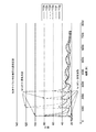
図2は、洗浄サイクル中の排気システムの温度応答を示すグラフである。センサ112b〜112gの各々(例えば、圧力制御バルブ113の下流にあるセンサ)において測定された温度が示されている。温度の相対スパイクは、イオン化洗浄ガスが堆積物質と反応する際の発熱性反応による温度の上昇、及び、閾値温度に到達したことに応じて洗浄ガスの流れが低減又は停止された際の温度の下降を、示している。温度が所定の設定点まで下降すると、後続の温度上昇によって示されているように、洗浄ガスの流れは再開する。図2に示しているように、約500秒のところで、センサ112cにおいて摂氏約100度という閾値温度に到達したことにより、洗浄ガス流量の低減が開始される。洗浄ガスの流量は、センサ112cにおける温度が摂氏30度に接近すると再開される。その後、およそ1100秒のところで、センサ112dにおいて約120度という閾値温度に到達したことにより、洗浄ガス流の低減が開始される。類似したピークイベントが、およそ1900秒、2500秒、3200秒、4000秒、5000秒、及び6000秒のところに図示されている。
FIG. 2 is a graph showing the temperature response of the exhaust system during the cleaning cycle. The temperature measured at each of the
上述のように、洗浄ガス流のサイクルは、排気システムが十分に洗浄されるまで継続する。ピーク振幅の継続的な低減は、排気システム内の堆積物質の減少(例えば、クロロシランなどの反応体の減少)を示している。図示しているように、約7000秒のところで、全てのセンサの排気システム内温度が周囲温度に接近しており、このことはプロセス終点を示す。 As mentioned above, the cleaning gas flow cycle continues until the exhaust system is thoroughly cleaned. A continuous reduction in peak amplitude indicates a reduction in sediment in the exhaust system (eg, a reduction in reactants such as chlorosilane). As shown, at about 7000 seconds, the temperature inside the exhaust system of all sensors approaches the ambient temperature, which indicates the end of the process.
排気システム102が上述のように洗浄された後、洗浄ガスや反応副生成物を排気システム102から全て除去するために、排気システム102はパージされうる。一例では、排気システム102は、洗浄プロセスのキャリアガス(アルゴンなど)を使用して、フラッシュ洗浄されうる。別の態様では、排気システム102は、分離バルブ109及び111が閉鎖位置にある状態で、窒素で再充填(backfill)され、かつフラッシュ洗浄されうる。排気システム102は、複数回(例えばおよそ5〜10回)にわたり、再充填され、フラッシュ洗浄されうる。
After the
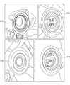
図3は、本書に記載の態様による、洗浄後の排気システムの諸セクションの内部図を示す。詳細には、図3は、圧力制御バルブ113の内部図を示している。図示しているように、本書に記載の態様により、圧力制御バルブ113は十分に洗浄されており、堆積物は見当たらない。洗浄は、圧力制御バルブ113に熱損傷を与えることなく行われている。
FIG. 3 shows an internal view of the sections of the exhaust system after cleaning according to the aspects described herein. In detail, FIG. 3 shows an internal view of the
本書に記載の態様の利点は、排気システムをより安全かつ迅速に洗浄することを含む。本書に記載の態様により、洗浄時間は、最大1か月から100分以下程度まで低減されうる。加えて、時間も費用もかかる予防保守の間の期間が延長されうる。更に、本書に記載の態様により、排気システムを解体する必要性が低減するか、又はなくなる(もし解体すれば、クロロシランが周囲酸素に暴露され、クロロシロキサンを形成することになる)。たとえ解体が必要になっても、この開示の態様によって洗浄された後であれば、露出される構成要素に存在するクロロシランは大幅に少なくなる。 Advantages of the embodiments described herein include cleaning the exhaust system more safely and quickly. Depending on the aspects described in this document, the cleaning time can be reduced from a maximum of 1 month to about 100 minutes or less. In addition, the time between time-consuming and costly preventive maintenance can be extended. In addition, the aspects described herein reduce or eliminate the need to dismantle the exhaust system (if dismantled, chlorosilane would be exposed to ambient oxygen to form chlorosiloxane). Even if disassembly is required, the amount of chlorosilane present in the exposed components will be significantly reduced after cleaning according to this disclosed aspect.
一例では、排気システムは、本書に記載の態様により洗浄される。解体時に、周囲環境において、1.5ppmという濃度の塩酸(クロロシランが周囲酸素と反応する際にガス放出される)が測定されるが、これは、5ppmという閾値よりも低い。対照的に、洗浄のために解体される従来型の排気システムは、周囲環境に暴露されると、5ppmというHCI濃度を超過することが多い。 In one example, the exhaust system is cleaned according to the aspects described herein. At the time of dismantling, hydrochloric acid at a concentration of 1.5 ppm (outgassing when chlorosilane reacts with ambient oxygen) is measured in the ambient environment, which is lower than the threshold of 5 ppm. In contrast, conventional exhaust systems that are dismantled for cleaning often exceed an HCI concentration of 5 ppm when exposed to the surrounding environment.
以上の説明は本開示の態様を対象としているが、本開示の基本的な範囲を逸脱しなければ、本開示の他の態様及び更なる態様が考案されてよく、本開示の範囲は以下の特許請求の範囲によって決まる。 Although the above description is intended for aspects of the present disclosure, other aspects and further aspects of the present disclosure may be devised as long as they do not deviate from the basic scope of the present disclosure, and the scope of the present disclosure is as follows. It depends on the scope of claims.
Claims (9)
前記プロセスチャンバに連結された排気システムと、を備える処理システムであって、前記排気システムが、
前記プロセスチャンバの下流で前記排気システムにイオン化洗浄ガスを供給するための遠隔プラズマ源、ここで前記遠隔プラズマ源は、洗浄ガスを前記遠隔プラズマ源へと流す入口を備える、
前記プロセスチャンバの下流にある第1分離バルブ、
前記遠隔プラズマ源の下流にある第2分離バルブ、
前記第1分離バルブ及び前記第2分離バルブの下流にある、圧力制御バルブ、
前記第1分離バルブ及び前記第2分離バルブの下流、及び前記圧力制御バルブの上流において前記排気システムの温度を測定するように構成された第1のセンサ、
前記圧力制御バルブの下流において前記排気システムの温度を測定するように構成された第2のセンサ、並びに
前記第1のセンサと前記第2のセンサから温度データを受け取り、前記排気システムの温度が所定の限界値を超えたとコントローラが判定したときに、前記遠隔プラズマ源から出るイオン化洗浄ガスの流量を低減するように構成されたコントローラ、を備える、処理システム。 A process chamber that processes the substrate internally,
A processing system comprising an exhaust system coupled to the process chamber, wherein the exhaust system
A remote plasma source for supplying an ionized cleaning gas to the exhaust system downstream of the process chamber , wherein the remote plasma source comprises an inlet for the cleaning gas to flow into the remote plasma source .
A first separation valve located downstream of the process chamber,
A second separation bulb downstream of the remote plasma source,
A pressure control valve located downstream of the first separation valve and the second separation valve.
A first sensor configured to measure the temperature of the exhaust system downstream of the first separation valve and the second separation valve, and upstream of the pressure control valve.
A second sensor configured to measure the temperature of the exhaust system downstream of the pressure control valve, as well as
When temperature data is received from the first sensor and the second sensor and the controller determines that the temperature of the exhaust system exceeds a predetermined limit value, the flow rate of the ionized cleaning gas emitted from the remote plasma source is reduced. A processing system , comprising a controller, which is configured to.
前記排気システムの測定された温度が第1の温度を超え、且つ第2の温度を下回ったときに、イオン化洗浄ガスの前記排気システムへの流れが減り、 When the measured temperature of the exhaust system exceeds the first temperature and falls below the second temperature, the flow of ionized cleaning gas to the exhaust system is reduced.
前記排気システムの測定された温度が前記第2の温度を超えたときに、前記イオン化洗浄ガスの前記排気システムへの流れを止める When the measured temperature of the exhaust system exceeds the second temperature, the flow of the ionized cleaning gas to the exhaust system is stopped.
ように前記遠隔プラズマ源から出るイオン化洗浄ガスの流量を制御するように構成されている、請求項1に記載の処理システム。The processing system according to claim 1, which is configured to control the flow rate of the ionized cleaning gas emitted from the remote plasma source.
前記プロセスチャンバに連結された排気システムと、を備える処理システムであって、前記排気システムが、
前記プロセスチャンバの下流で前記排気システムにイオン化洗浄ガスを供給するための、遠隔プラズマ源、ここで前記遠隔プラズマ源は、洗浄ガスを前記遠隔プラズマ源へと流す入口を備える、
前記プロセスチャンバの下流にある第1分離バルブ、
前記遠隔プラズマ源の下流にある第2分離バルブ、
前記第1分離バルブ及び前記第2分離バルブの下流にある、圧力制御バルブ、
前記第1分離バルブ及び前記第2分離バルブの下流、及び前記圧力制御バルブの上流において前記排気システムの温度を測定するように構成された第1のセンサ、
前記圧力制御バルブの下流において前記排気システムの温度を測定するように構成された第2のセンサ、
前記第1のセンサと前記第2のセンサから温度データを受け取り、前記排気システムの温度が所定の限界値を超えたとコントローラが判定したときに、前記遠隔プラズマ源から出るイオン化洗浄ガスの流量を低減するように構成されたコントローラ、
前記圧力制御バルブの下流にある終点検出システム、並びに
前記終点検出システムの下流にある真空ポンプ、を備える、処理システム。 A process chamber that processes the substrate internally,
A processing system comprising an exhaust system coupled to the process chamber, wherein the exhaust system
A remote plasma source for supplying an ionized cleaning gas to the exhaust system downstream of the process chamber , wherein the remote plasma source comprises an inlet for the cleaning gas to flow into the remote plasma source .
A first separation valve located downstream of the process chamber,
A second separation bulb downstream of the remote plasma source,
A pressure control valve located downstream of the first separation valve and the second separation valve.
A first sensor configured to measure the temperature of the exhaust system downstream of the first separation valve and the second separation valve, and upstream of the pressure control valve.
A second sensor configured to measure the temperature of the exhaust system downstream of the pressure control valve.
When temperature data is received from the first sensor and the second sensor and the controller determines that the temperature of the exhaust system exceeds a predetermined limit value, the flow rate of the ionized cleaning gas emitted from the remote plasma source is reduced. Controllers configured to
Endpoint detection system downstream of the pressure control valve, and comprises a vacuum pump, downstream of the endpoint detection system, processing system.
前記排気システムの測定された温度が第1の温度を超え、且つ第2の温度を下回ったときに、イオン化洗浄ガスの前記排気システムへの流れが減り、 When the measured temperature of the exhaust system exceeds the first temperature and falls below the second temperature, the flow of ionized cleaning gas to the exhaust system is reduced.
前記排気システムの測定された温度が前記第2の温度を超えたときに、前記イオン化洗浄ガスの前記排気システムへの流れを止める When the measured temperature of the exhaust system exceeds the second temperature, the flow of the ionized cleaning gas to the exhaust system is stopped.
ように前記遠隔プラズマ源から出るイオン化洗浄ガスの流量を制御するように構成されている、請求項6に記載の処理システム。The processing system according to claim 6, which is configured to control the flow rate of the ionized cleaning gas emitted from the remote plasma source.
Applications Claiming Priority (3)
| Application Number | Priority Date | Filing Date | Title |
|---|---|---|---|
| US201662327870P | 2016-04-26 | 2016-04-26 | |
| US62/327,870 | 2016-04-26 | ||
| PCT/US2017/025999 WO2017189194A1 (en) | 2016-04-26 | 2017-04-04 | Temperature controlled remote plasma clean for exhaust deposit removal |
Publications (3)
| Publication Number | Publication Date |
|---|---|
| JP2019518327A JP2019518327A (en) | 2019-06-27 |
| JP2019518327A5 JP2019518327A5 (en) | 2020-05-14 |
| JP6924775B2 true JP6924775B2 (en) | 2021-08-25 |
Family
ID=60089372
Family Applications (1)
| Application Number | Title | Priority Date | Filing Date |
|---|---|---|---|
| JP2018555590A Active JP6924775B2 (en) | 2016-04-26 | 2017-04-04 | Temperature-controlled remote plasma cleaning for removal of exhaust deposits |
Country Status (6)
| Country | Link |
|---|---|
| US (1) | US10500614B2 (en) |
| JP (1) | JP6924775B2 (en) |
| KR (1) | KR102194085B1 (en) |
| CN (1) | CN109069990B (en) |
| TW (1) | TWI702093B (en) |
| WO (1) | WO2017189194A1 (en) |
Families Citing this family (3)
| Publication number | Priority date | Publication date | Assignee | Title |
|---|---|---|---|---|
| US11332824B2 (en) * | 2016-09-13 | 2022-05-17 | Lam Research Corporation | Systems and methods for reducing effluent build-up in a pumping exhaust system |
| KR20210009428A (en) * | 2018-06-14 | 2021-01-26 | 엠케이에스 인스트루먼츠 인코포레이티드 | Radical Output Monitor and How to Use for Remote Plasma Sources |
| JP7374158B2 (en) | 2021-10-15 | 2023-11-06 | 株式会社荏原製作所 | Product removal device, treatment system and product removal method |
Family Cites Families (16)
| Publication number | Priority date | Publication date | Assignee | Title |
|---|---|---|---|---|
| DE19922960C2 (en) * | 1999-05-19 | 2003-07-17 | Daimler Chrysler Ag | Emission control system with internal ammonia production for nitrogen oxide reduction |
| US6592817B1 (en) * | 2000-03-31 | 2003-07-15 | Applied Materials, Inc. | Monitoring an effluent from a chamber |
| US20030207021A1 (en) * | 2000-04-28 | 2003-11-06 | Hiroshi Izawa | Deposited-film formation apparatus, deposited-film formation process, vacuum system, leak judgment method, and computer-readable recording medium with recorded leak-judgment- executable program |
| JP2006004962A (en) * | 2004-06-15 | 2006-01-05 | Canon Inc | Deposited film forming device and its cleaning method |
| JP2006086156A (en) * | 2004-09-14 | 2006-03-30 | Canon Inc | Method for removing product |
| TWI279260B (en) * | 2004-10-12 | 2007-04-21 | Applied Materials Inc | Endpoint detector and particle monitor |
| US7819981B2 (en) * | 2004-10-26 | 2010-10-26 | Advanced Technology Materials, Inc. | Methods for cleaning ion implanter components |
| US20060211253A1 (en) * | 2005-03-16 | 2006-09-21 | Ing-Shin Chen | Method and apparatus for monitoring plasma conditions in an etching plasma processing facility |
| US20060266288A1 (en) * | 2005-05-27 | 2006-11-30 | Applied Materials, Inc. | High plasma utilization for remote plasma clean |
| US7210338B2 (en) * | 2005-07-29 | 2007-05-01 | Honda Motor Co., Ltd. | Valve testing device having integrated purge circuit and method of valve testing |
| WO2007041454A2 (en) * | 2005-10-03 | 2007-04-12 | Advanced Technology Materials, Inc. | Systems and methods for determination of endpoint of chamber cleaning processes |
| JP4876242B2 (en) * | 2005-12-16 | 2012-02-15 | 国立大学法人静岡大学 | Crystal growth method and crystal growth apparatus |
| KR101213689B1 (en) * | 2006-06-12 | 2012-12-18 | 주식회사 테라텍 | Apparatus for cleaning exhaust portion and vacuum pump of the semiconductor and LCD process reaction chamber |
| JP2011111655A (en) * | 2009-11-27 | 2011-06-09 | Sharp Corp | Method for cleaning plasma cvd apparatus, method for forming semiconductor thin film, method for manufacturing photoelectric conversion element, and plasma cvd apparatus |
| CN102758669A (en) * | 2011-04-26 | 2012-10-31 | 陈温乐 | Neutralization temperature reduction treatment device for exhaust waste gas of vehicle |
| KR101427726B1 (en) * | 2011-12-27 | 2014-08-07 | 가부시키가이샤 히다치 고쿠사이 덴키 | Substrate processing apparatus and method of manufacturing semiconductor device |
-
2017
- 2017-04-04 WO PCT/US2017/025999 patent/WO2017189194A1/en active Application Filing
- 2017-04-04 KR KR1020187033749A patent/KR102194085B1/en active IP Right Grant
- 2017-04-04 JP JP2018555590A patent/JP6924775B2/en active Active
- 2017-04-04 CN CN201780025125.1A patent/CN109069990B/en active Active
- 2017-04-05 US US15/479,609 patent/US10500614B2/en active Active
- 2017-04-19 TW TW106113035A patent/TWI702093B/en active
Also Published As
| Publication number | Publication date |
|---|---|
| TW201801813A (en) | 2018-01-16 |
| CN109069990A (en) | 2018-12-21 |
| TWI702093B (en) | 2020-08-21 |
| JP2019518327A (en) | 2019-06-27 |
| US10500614B2 (en) | 2019-12-10 |
| KR102194085B1 (en) | 2020-12-22 |
| KR20180128082A (en) | 2018-11-30 |
| CN109069990B (en) | 2021-11-16 |
| WO2017189194A1 (en) | 2017-11-02 |
| US20170304877A1 (en) | 2017-10-26 |
Similar Documents
| Publication | Publication Date | Title |
|---|---|---|
| JP6924775B2 (en) | Temperature-controlled remote plasma cleaning for removal of exhaust deposits | |
| TW202108818A (en) | Method for in-situ cleaning a reaction chamber and semiconductor film deposition system | |
| KR100887906B1 (en) | High pressure wafer-less auto clean for etch applications | |
| US9970112B2 (en) | Substrate processing apparatus and method of manufacturing semiconductor device | |
| KR100767804B1 (en) | A method and device for controlling a cleaning cycle | |
| KR100881045B1 (en) | Duo-step plasma cleaning of chamber residues | |
| JP5780695B2 (en) | Thin film forming apparatus cleaning method, thin film forming method, and thin film forming apparatus | |
| US20130133697A1 (en) | Prevention of post-pecvd vacuum and abatement system fouling using a fluorine containing cleaning gas chamber | |
| JPH1174258A (en) | Method and device for obtaining final point in plasma cleaning process | |
| KR100806041B1 (en) | An apparatus for fabricating semiconductor device and a method of fabricating semiconductor device using the same | |
| JP5166138B2 (en) | Semiconductor device manufacturing method and semiconductor device manufacturing apparatus | |
| KR20210009366A (en) | Techniques to enable high temperature cleaning for rapid processing of wafers | |
| CN112020766A (en) | Apparatus for gas byproduct abatement and foreline cleaning | |
| KR100611612B1 (en) | Method and apparatus for determining cleaning process end point using throttle valve position | |
| KR20130105308A (en) | Deposition chamber cleaning using in situ activation of molecular fluorine | |
| JP2011058033A (en) | Method for suppressing deposition of ammonium silicofluoride in exhaust gas treatment system piping | |
| US20090041925A1 (en) | System and Method for Endpoint Detection of a Process in a Chamber | |
| TWI794194B (en) | Virtual sensor for chamber cleaning endpoint | |
| JP2005108932A (en) | Semiconductor manufacturing apparatus | |
| US20150187562A1 (en) | Abatement water flow control system and operation method thereof | |
| US20180330929A1 (en) | In-situ removal of accumulated process byproducts from components of a semiconductor processing chamber | |
| JP2003051452A (en) | Method of manufacturing semiconductor device and substrate processing apparatus | |
| JPH10163116A (en) | Semiconductor device | |
| JP2007287935A (en) | Vapor phase epitaxy device, and method for manufacturing semiconductor device using it | |
| CN108114585B (en) | Method for operating a plasma gas scrubber |
Legal Events
| Date | Code | Title | Description |
|---|---|---|---|
| A521 | Written amendment |
Free format text: JAPANESE INTERMEDIATE CODE: A523 Effective date: 20200403 |
|
| A621 | Written request for application examination |
Free format text: JAPANESE INTERMEDIATE CODE: A621 Effective date: 20200403 |
|
| A977 | Report on retrieval |
Free format text: JAPANESE INTERMEDIATE CODE: A971007 Effective date: 20210412 |
|
| A131 | Notification of reasons for refusal |
Free format text: JAPANESE INTERMEDIATE CODE: A131 Effective date: 20210420 |
|
| TRDD | Decision of grant or rejection written | ||
| A01 | Written decision to grant a patent or to grant a registration (utility model) |
Free format text: JAPANESE INTERMEDIATE CODE: A01 Effective date: 20210706 |
|
| A61 | First payment of annual fees (during grant procedure) |
Free format text: JAPANESE INTERMEDIATE CODE: A61 Effective date: 20210802 |
|
| R150 | Certificate of patent or registration of utility model |
Ref document number: 6924775 Country of ref document: JP Free format text: JAPANESE INTERMEDIATE CODE: R150 |