EP1148954B1 - Auftragen einer auftragsschicht auf einen dünnwandigen behälter - Google Patents
Auftragen einer auftragsschicht auf einen dünnwandigen behälter Download PDFInfo
- Publication number
- EP1148954B1 EP1148954B1 EP99965393A EP99965393A EP1148954B1 EP 1148954 B1 EP1148954 B1 EP 1148954B1 EP 99965393 A EP99965393 A EP 99965393A EP 99965393 A EP99965393 A EP 99965393A EP 1148954 B1 EP1148954 B1 EP 1148954B1
- Authority
- EP
- European Patent Office
- Prior art keywords
- application
- roller
- layer
- process according
- peripheral
- Prior art date
- Legal status (The legal status is an assumption and is not a legal conclusion. Google has not performed a legal analysis and makes no representation as to the accuracy of the status listed.)
- Expired - Lifetime
Links
- 239000011247 coating layer Substances 0.000 title abstract description 5
- 239000002184 metal Substances 0.000 claims abstract description 81
- 238000000034 method Methods 0.000 claims abstract description 40
- 230000002093 peripheral effect Effects 0.000 claims abstract description 33
- 230000000295 complement effect Effects 0.000 claims abstract description 5
- 239000003973 paint Substances 0.000 claims description 60
- 230000008569 process Effects 0.000 claims description 36
- 239000004922 lacquer Substances 0.000 claims description 21
- 230000033001 locomotion Effects 0.000 claims description 12
- 230000001360 synchronised effect Effects 0.000 claims description 11
- 230000008859 change Effects 0.000 claims description 9
- 230000003247 decreasing effect Effects 0.000 claims description 7
- 238000005096 rolling process Methods 0.000 claims description 4
- 238000004519 manufacturing process Methods 0.000 claims description 3
- 238000006243 chemical reaction Methods 0.000 claims description 2
- 230000007774 longterm Effects 0.000 claims description 2
- 239000010410 layer Substances 0.000 abstract description 95
- 238000000576 coating method Methods 0.000 abstract description 11
- 239000011248 coating agent Substances 0.000 abstract description 10
- 238000009877 rendering Methods 0.000 abstract 1
- 238000009826 distribution Methods 0.000 description 17
- 230000005540 biological transmission Effects 0.000 description 13
- 239000002966 varnish Substances 0.000 description 6
- 230000007423 decrease Effects 0.000 description 5
- 230000000694 effects Effects 0.000 description 4
- 239000002516 radical scavenger Substances 0.000 description 4
- ATJFFYVFTNAWJD-UHFFFAOYSA-N Tin Chemical compound [Sn] ATJFFYVFTNAWJD-UHFFFAOYSA-N 0.000 description 3
- 238000009825 accumulation Methods 0.000 description 3
- 230000035508 accumulation Effects 0.000 description 3
- 235000013361 beverage Nutrition 0.000 description 3
- 238000003860 storage Methods 0.000 description 3
- 230000015572 biosynthetic process Effects 0.000 description 2
- 230000008878 coupling Effects 0.000 description 2
- 238000010168 coupling process Methods 0.000 description 2
- 238000005859 coupling reaction Methods 0.000 description 2
- 230000002123 temporal effect Effects 0.000 description 2
- 208000012886 Vertigo Diseases 0.000 description 1
- 238000002679 ablation Methods 0.000 description 1
- 238000005299 abrasion Methods 0.000 description 1
- 239000000853 adhesive Substances 0.000 description 1
- 230000001070 adhesive effect Effects 0.000 description 1
- 230000001427 coherent effect Effects 0.000 description 1
- 238000011109 contamination Methods 0.000 description 1
- 230000006866 deterioration Effects 0.000 description 1
- 238000005516 engineering process Methods 0.000 description 1
- 238000005530 etching Methods 0.000 description 1
- 239000012530 fluid Substances 0.000 description 1
- 230000001788 irregular Effects 0.000 description 1
- 239000000314 lubricant Substances 0.000 description 1
- 230000007257 malfunction Effects 0.000 description 1
- 230000003287 optical effect Effects 0.000 description 1
- 238000010422 painting Methods 0.000 description 1
- 238000007639 printing Methods 0.000 description 1
- 238000000926 separation method Methods 0.000 description 1
- 238000010008 shearing Methods 0.000 description 1
- 239000013589 supplement Substances 0.000 description 1
- 230000007704 transition Effects 0.000 description 1
- 238000009736 wetting Methods 0.000 description 1
Images


Classifications
-
- B—PERFORMING OPERATIONS; TRANSPORTING
- B05—SPRAYING OR ATOMISING IN GENERAL; APPLYING FLUENT MATERIALS TO SURFACES, IN GENERAL
- B05D—PROCESSES FOR APPLYING FLUENT MATERIALS TO SURFACES, IN GENERAL
- B05D1/00—Processes for applying liquids or other fluent materials
- B05D1/28—Processes for applying liquids or other fluent materials performed by transfer from the surfaces of elements carrying the liquid or other fluent material, e.g. brushes, pads, rollers
-
- B—PERFORMING OPERATIONS; TRANSPORTING
- B05—SPRAYING OR ATOMISING IN GENERAL; APPLYING FLUENT MATERIALS TO SURFACES, IN GENERAL
- B05C—APPARATUS FOR APPLYING FLUENT MATERIALS TO SURFACES, IN GENERAL
- B05C1/00—Apparatus in which liquid or other fluent material is applied to the surface of the work by contact with a member carrying the liquid or other fluent material, e.g. a porous member loaded with a liquid to be applied as a coating
- B05C1/02—Apparatus in which liquid or other fluent material is applied to the surface of the work by contact with a member carrying the liquid or other fluent material, e.g. a porous member loaded with a liquid to be applied as a coating for applying liquid or other fluent material to separate articles
- B05C1/022—Apparatus in which liquid or other fluent material is applied to the surface of the work by contact with a member carrying the liquid or other fluent material, e.g. a porous member loaded with a liquid to be applied as a coating for applying liquid or other fluent material to separate articles to the outer surface of hollow articles
Definitions
- the invention relates to a method for applying an application or top layer, in particular a white lacquer layer, to beverage cans as a representative representative of a thin-walled metal can.
- a method for applying an application or top layer, in particular a white lacquer layer, to beverage cans as a representative representative of a thin-walled metal can.
- Such a method is usually referred to in the prior art as "white coating" because the lacquer layer which is applied to the metal can is the primer layer in order to apply other layers of color to the can later, cf. also EP-B 050 269 (Schmalbach-Lubeca).
- the solution is based on the idea of applying, i.e. transferring the No application layer from a transfer roller to the thin-walled metal can Differential speed to provide and practically no slip for the temporal Let the section of the application take effect.
- the transfer roller already has the ability to apply evenly Application device a different on their surface (different thick) applied layer in the form of successive repeat lengths of Application layer sections that are non-slip - without the slip mentioned on the thin-walled box is transferred, with two circumferential sections on the overlap metallic tin in opposite directions to create a uniformly strong one To result in total layer or layer layer.
- Two layer sections are for the opposite addition needed, so that the sum of the layer thicknesses such Sections on the transfer roller, one on top of the other, on the metallic can lie together, an order equally strong over the circumference of the metal can result.
- the non-slip transmission of the on a much larger scale temporarily stored paint layer course in the form of several repeat lengths, with a repeat length assigned to a can ensures that the preselected one and previously certain paint thickness is transferred very precisely to the metal can, which is carried out in the application process on the transfer roller, in which Completing two paint layers sections complement each other on the metal can come to lie on top of each other while they are still on the transfer roller were arranged side by side (circumferentially).
- the paint layer applied on the outside was still “misused” as a lubricant, which briefly absorbed the considerable differential speed from the faster rotating can to the slower rotating transfer roller, but was also required to prevent a paint jam from occurring in the feed area
- the predetermined coating thickness distribution due to the predetermined coating thickness distribution, it can be ensured already on the transfer roller and the practically the same rotational speed that the application layer is applied directly and gently to the inside of the metal can without the formation of jams.
- a control of the speed difference during the Order process is no longer necessary because it is also in the end area of the order process only exactly that amount is transferred to the metal body without slipping that at the respective extensive position for complementary addition and formation of a extensive constant order layer is required. It therefore arises In addition, a simplification of the control technology in that different Speeds of the thin-walled metal cans during the order are unnecessary.
- the preparatory application of the different layer thicknesses is carried out by one further roller, which is connected to the transmission device, in particular compared to the area in which the thickness distribution is predetermined Application layer is transferred from the transfer roller to the metal cans (Claim 5, 6, 7 and 9).
- the first roller has the layer thickness circumferentially determines a surface which has trough regions arranged along strips, which troughs in accordance with the predetermined layer thickness distribution Circumferential direction run deeper or flatter to change accordingly take up more or less varnish, which after application to the first roller of a surface-mounted doctor blade or slide is leveled on the surface, in particular is removed entirely above the depressions.
- Another removal device can be in the form of a small roller on the circumference of the Transfer roller be arranged in the area after the application area on the Metal cans and in front of the area where the first roller applied the thickness controlled varnish transfers to the application device (transfer roller). So it can be achieved that remaining paint residues are removed from the application device before a new thickness-controlled layer is applied to the application device.
- the Removal device in the form of a roller can also add another doctor blade own that works similar to the squeegee or slide that works on the circumference of the first roller was provided. The removal of remaining paint volume ensures to ensure that the new order always remains evenly distributed.
- the remaining residues may be due to the fact that the varnish is either not was completely transferred to the metal cans that the metal cans may not were supplied and the entire paint layer was still left or irregular remnants due to incorrect feeding or incorrect transmission remain. All possible errors in the order strip are the same switched off.
- the rollers in contact with each other can be synchronized with each other.
- a Synchronization ensures that the respective starting points of repeat lengths, i.e. one such length, which is assigned to a single can and the circumference the application roller are arranged one after the other, again and again in the course of Rotating motion collide. It doesn't matter if the starting points are integer multiples of repeat lengths after a complete rotation change if the circumferential lengths are coordinated so that the Start of repeat lengths of opposite and touching In the long term, rollers always meet such starting points. A drift away of color thicknesses within a repeat length, especially an uncontrolled one Changes in the color thickness in these application strips can thus be avoided.
- the synchronization can affect the speed if the circumferential lengths in one fixed predetermined ratio so that a respective integer of Repeat lengths can be found on any circumference, for example when the Diameter in a ratio of 1: 2: 4 (take-off roller, application roller, Transfer roller).
- the term integer is understood in the sense of a Integer number (claim 17).
- the process of applying the application layer can be kept in balance, if, in the absence of cans, the repeat lengths of Application layers, working in opposite directions, an abrasion roller to the transfer roller is employed. This can be done with a slight delay, depending on how many Containers are still present on the spoke wheel and are able to Repeat pattern lengths to be removed from the application roller. With that the renewed Switching on improved because the order thickness of the repeat lengths is not uncontrolled drifts. Likewise, the build-up of too thick application layers on the Transfer roller can be prevented. You can also use several removal rollers successively be provided by more than 50% ( ⁇ 10%) from the applicator roll to decrease. In a subsequent start-up, only a few cans are considered "Starting cans" needed, usually no more than ten, that did not have an acceptable paint application have.
- the holding devices on which the thin-walled metal containers sit and on which they are held so by axial or radial forces that they are in the Application process are able to provide the necessary reaction forces apply anyway due to the chosen speed when applying are very small, rotatable mandrels (claim 12, 13).
- These thorns are there on a spoke wheel, the diameter of which is significantly larger than the diameter of the Transfer roller can be and on which - at the respective ends of the spokes - the thin-walled held on the rotatable holding devices (thorns) Store metal container.
- the force to hold the metal container can be achieved by vacuum or can also be applied to the bottom of the respective can by magnetic force, so that driving the respective domes before touching and forming one striped application area causes the differential speed especially at the time of the first touch and especially at the time of loosening is practically zero and preferred for the entire duration of the training a striped order area, i.e. the entire duration of the application practically no difference speed exists.
- the layer on the layer that begins at a practically zero coating thickness cylindrical transmission device ensures avoiding initial paint jams when transferring a steadily thicker one becoming layer section on the same speed as that Transmission device rotating metal cans (claim 4, 8).
- the thickness of the varnish layer can be controlled as coherent color layer or as a structured lacquer layer with still existing paint strips and areas that do not carry paint his.
- the layer is only structureless after it has been transferred to the metal cans and uniform.
- the stripe areas are a result of the troughed, surface engraved especially in the first section of a roto-engraving process the first roller (claim 5).
- This textured surface has a period that begins their scope remains the same and is in a respective period section a trough that changes either in width or in depth at the perimeter to prepare a changing volume on this first roller, the then onto the transfer roller - especially in the second section of the roto-engraving process - is transmitted rotatively, where the structure is not preserved and especially at higher speeds and larger coating volumes per peripheral unit here already a steady course of the shift becomes.
- the application layer which is arranged in a circumferentially distributed manner can also be understood in this way be that a volume of paint per unit volume is on the surface of the transfer roller changes, in particular at least in sections steadily increasing or steadily decreasing or also constant for intermediate sections (claim 8).
- pulse duration modulation here spatial, not temporal
- trough depth or trough width for one That gives a constant circumferential distance that defines the period Volume per circumferential element, for example per distance R before that on the Transmission device is transmitted.
- the described period of the troughs is the small period.
- the big period is that of the repeat lengths.
- the grid guides or strips along those Troughs are not perpendicular and not parallel to the axis, rather inclined to the circumferential direction, usually at an angle between 30 ° and 60 °.
- the troughs are embedded in two sets of strips that cross and the have said angles to the axis, so that these strips are preferred cut at an angle of 90 °.
- the sequence of depths or sizes of the troughs are provided so that along a parallel to the axis there is the same trough size or trough depth. Change in the circumferential direction Trough size or trough depth.
- the procedure for defining these troughs can be galvanic, mechanical with a Graver (diamond-shaped) or optically with a laser.
- Dome shapes are preferred in galvanic production.
- the optical design of the troughs with a laser offers the most extensive designs of the wells, in which the inclined flanks are practical can have any shape and the basic shape does not necessarily have one polygonal base must be on the surface of the roller.
- the start area of a job section on the transmission device for transfer to a hollow body is advantageous because it can be avoided may cause a build-up of paint when first applied and therefore the same Application speeds of both the target object and the cylindrical one Transmission device is possible.
- the then constantly changing layer thickness when applying and the later complementary second layer thickness at two Order shifts (repeatable in corresponding shift pairs on the target object) result in a uniformly well-developed circumferentially on the target object Application layer, especially top or lacquer layer.
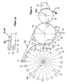
- FIG. 1 shows a spoke wheel 60 known in the prior art, which has a plurality of spokes 60a, 60b, 60c which extend radially and at whose respective ends a short cylindrical holding piece 21 which extends parallel to the axis 60z of the spoke wheel, on the cylindrical container body, in particular thin-walled beverage cans, for example according to DE 28 05 271 C2 (Schmalbach-Lubeca).
- the cans 20, which can only be seen here in section with their thin wall thickness, are held by magnetic forces or suction forces that act on the bottom of the can so that they cannot be easily rotated circumferentially relative to the rotatably mounted cylinder holder 21, rather are rotatable together with this during a rotation.
- the spoke wheel moves in the circumferential direction at the circumferential speed v 60 , shown here clockwise.
- a transfer roller 30 with an axis of rotation 30a is shown, the diameter of which is significantly smaller than that of the length of the spokes of the spoke wheel and which comes into contact with the metallic cans 20 in an application area 22, which will be explained in more detail later.
- the transfer roller 30 receives a circumferentially thickness-controlled predetermined layer of applied lacquer from a surface-structured applicator roller 40 rotating about an axis 40a as a gravure roller, which is fed by a lacquer storage 51 and, after application, carries a certain amount of lacquer per peripheral unit.
- the surface of the lacquer layer is removed from a transverse doctor arm 50 arranged behind the ink application 51, so that lacquer only remains in the structures of the application roller 40 (gravure roller).
- the directions of rotation of the transfer roller 30 and the application roller 40 are such that all three elements, the metal cans 20, the transfer roller 30 and the application roller 40 have the same speeds in the contact area, in particular are synchronized.
- a take-off roller 52 is arranged below the transfer roller 30, namely in the intermediate area after the order area 22 between the metal can 20 and transfer roller 30 and in front of the application roller 40.
- the surface of the transfer roller which is mostly called a blanket cylinder will be trained.
- Remaining paint residue or paint residue on the Surface of the transfer cylinder 30 can be faulty or incomplete Transmission in the order area 22 can be traced back to the metal cans. If no such metal cans are supplied, practically the complete one remains predetermined paint on the surface of the transfer roller and is from the Removal roller 52 at least partially removed before a new one Transfer the paint thickness profile from the applicator roller 40 to the blanket cylinder 30 becomes. Adhesive forces ensure that between 40% and 60% of the paint is removed by the rotating small roller 52, which itself has another doctor blade 52a can, similar to the doctor blade 50 on the applicator roller 40.
- the cylindrical holding devices also called “mandrels” 21, can be rotated according to FIG. 1a about the axis 21a at the end of a respective spoke of the spoke wheel.
- the rotary movement is initiated by a conveyor belt 31 shown here, which runs from the transfer roller 30 via a coupling roller 32 and then engages extensively on a plurality of holding devices 21 and thus brings the cans sitting on them into a predetermined rotational movement.
- a transfer roller 30 can also be provided with a rubber ring 31a fixedly arranged thereon via a connecting section 33, which acts on a respective mandrel 21 with pressure force, so that slippage can be avoided and the drive at the same speed on the peripheries of the can 20 and the application roller 30 takes place.
- the cans 20 have a slight drop in the direction of the spokes 60a, 60b, 60c when the metal containers touch the circumference of the transfer roller 30, usually a blanket roller with a superficially arranged printing blanket which is arranged on a soft rubber base is stronger than the blanket on top.
- the cans experience a slight inward movement as a "pitch", directed essentially in the radial direction towards the axis 60z of the spoke wheel.
- the smaller this vertical runout the less complex the mechanical precautions on the spoked wheel 60.
- the contact angle shown in FIG. 1 is the area of rotation V 60 in which the vertical runout is controlled, for example, by cams. In the contact angle range, the contact pressure is thus the same, with the speed of the respective surfaces in the contact area 22, which is already existing, in the contact area 22, which will be explained later.
- the area 22 at which the metal cans 20 begin to come into contact with the transfer roller 30 is of greater importance, which is shown here in the area in which the speeds v A and v B are shown. These speeds are indicated at the point of contact of the clockwise rotating spoke wheel with the likewise clockwise rotating holding devices 21 and metal cans 20 and the counterclockwise transfer roller 30.
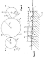
- This narrow strip region 22 which is formed becomes clearer in the schematic illustration in FIG .
- the transfer roller 30 is shown with a larger diameter than the metal cans 20.
- the speeds v A and v B are the same and a strip-shaped application area 22 is formed between these two cylinders, which enables the transfer of the transfer roller 30 in one given the thickness distribution of the existing color layer on the surface of the metal can 20.
- a similar strip area 22a is formed between the application roller 40 and the transfer roller 30 on the left in FIG. 2 (on the right in FIG. 1). In this strip 22a too, v A and v C are the same.
- the transfer of lacquer in the strip area 22a is to be illustrated with reference to FIG. 1b .
- the surface of the application roller 40 is unwound and shown in a greatly enlarged section.
- the surface W of the application roller 40 contains wells which are defined in a punctiform manner from many parallel lines, which lines do not extend parallel to the axis of the application roller 40, but rather run at an oblique angle of between preferably 30 ° to 60 ° or 120 ° to 150 °.
- the depth t as a function along the circumference changes in accordance with the desired thickness of the lacquer along the circumference of the transfer roller 30.
- the troughs in the example shown become ever deeper with a constant period R, so that increasingly greater depths t a , t b , t c and thus form a correspondingly larger volume of lacquer-receiving troughs 41a, 41b, 41c.
- These troughs and thus the design of the surface of the application roller 40 can be created optically by laser or by engraving or exposure and etching. They allow the thickness (the volume) to be controlled along the circumference, which can be specified more precisely, the finer the grid R and the shorter a period of the trough sequence, into which a respective land area S, in which the original cylinder jacket remains without removal.
- a constant change in depth or width along the circumference ensures at least in sections for a steady increase in the amount of paint per Circumferential section and thus for a correspondingly increasing or falling paint thickness on the transfer roller 30.
- Figure 1c is a plan view of the surface W of Figure 1b, indicated as a section of the surface of the applicator roller 40.
- the troughs 41a, 41b, 41c (short: 41) are shown increasing in the direction of movement V c here, with a grid of auxiliary lines 46, which are perpendicular to each other and enclose an angle of 45 ° or 135 ° with an axis parallel.
- the grid R can be seen, in which the sequence of the troughs is arranged.
- the land areas S are also included, which in FIG. 1b come to lie in cross section between two neighboring troughs.
- the angle of 45 ° drawn in for the auxiliary lines can be in a range between 30 ° and 60 °, while maintaining the vertical orientation of the auxiliary lines, which are only indicated in FIG. 1c, in order to clarify the course of the trough depths and their arrangement.
- Troughs 41a each have the same depth or size in the axial direction 40a. In the direction V c , the troughs become deeper or larger if an increasing paint thickness is desired. The same applies to a thickness of paint that decreases in thickness. If the paint thickness remains the same in one section, the sizes or depths of the depressions 41a, 41b or 41c do not change in the circumferential direction either.
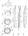
- FIG. 4a Such a thickness distribution is shown in FIG. 4a as an averaged course in the unwound state.
- the paint volume transferred initially increases from a starting point 12 over an angle of 180 ° - based on the circumference of the metal can 20 according to FIG. 3a - to a point 13.
- the thickness of the applied lacquer from the application roller 40 to the transfer roller 30 remains unchanged, i.e. remains constant during 180 ° again - based on the circumference of the metal can 20 held by the mandrel 21 from FIG. 3 - and then drops between points 14 and 15 in Figure 3b to a lower thickness value.
- Varnish is explained here as an example of a paint or other layer application; any fluid that is to hold onto the hollow body can be transferred in a predetermined thickness.
- the "dots" 12, 13, 14, 15 of FIG. 4 are lines perpendicular to the paper plane. A repeat length is intended for a container and extends from 12 to 15 in FIGS. 4.
- the constant layer height d 1 again meets the initially applied layer thickness d 0 ( ⁇ ), which increases linearly from zero, because the can has covered a complete revolution.
- a second layer 11b which is steadily reducing in thickness, is applied in order to obtain an extensively constant application thickness, which corresponds to the thickness d 1 in the range between 13 and 14, an overlap region u being created, which leads to FIG. 3c and there is shown as d 2 ( ⁇ ).
- the layer d 0 ( ⁇ ) of FIG. 3a which grows continuously over the circumference, and the layer d 2 ( ⁇ ) of FIG.
- An application layer is thus applied to the metal can 20, which in its extensively controlled course before application already on the transfer roller 30 was specified and after application without slip and with the same Speed in the strip area 22 of FIG. 2 has a constant thickness distribution a total layer 10 generated over the entire can surface.
- FIG. 4b This is illustrated in FIG. 4b , in which the striped area represents the layers transferred to the metal can 20 and the non-striped lower area illustrates the remaining “rest” on the transfer roller 30.
- the first transferred area d 0 ( ⁇ ) which changes continuously in thickness, is overlapped in the overlap area ü by the layer layer d 2 ( ⁇ ) that was applied last and is continuously reduced in thickness, and forms a constant lacquer thickness in the overlap area ü, which was previously used the layer thickness d 1 was applied in the intermediate area. Part of the rest is removed from the surface of the transfer cylinder with the take-off roller 52.
- the volume distribution of the ink layer according to FIG. 4c on the application roller 40 is required. It is - since it also does not correspond in diameter to the diameter of the can 20 - so distributed around the circumference that a plurality of color layer thickness distributions (repeat lengths) arranged one behind the other can be provided for several metal cans and are correspondingly transferred successively to the larger transfer roller 30, before they are then placed on individual cans one after the other and provided with an overlap area "ü". It can be seen from FIG. 4c that even the entire volume that is waiting for transfer over the entire circumference in the strip-shaped depressions of FIG.
- the surface of the metal can 20 and the strip area 22 to the transfer roller 30 have no different speeds so that the forces acting on the metal can 20 are minimal. These minimal forces can be easily applied by the holding device 21 and this prevents the metal can 20 from slipping on the cylindrical holding device 21 and the inside of the metal can 20 being damaged.
- High speeds in the strip area 22 can be achieved in this way, from 8 m / sec up to 10 m / sec and 12 m / sec, the strip area 22 apparently running around the axis 21a of the rotatable holding device on the spoke wheel 60, but actually in opposite directions between them rotating cylinder bodies that come into contact in this strip area and remain locally in practically the same place if a small circumferential segment is neglected during the rotational movement of the spoke wheel 60, which can be seen in FIG. 1 between the spokes 60a and 60c. This very short segment results from the slow rotation of the spoke wheel and the very fast rotation of the metal can.
- the strip area is possibly structured on the application device 30 in circumferentially spaced strips of paint layer uniformized and a continuous layer on the metal body 20 without, however, inner To be subjected to shear effects in the paint layer thickness, which only at various circumferential speeds of the order area colliding cylinders that roll against each other.
- the after the separation of the rolling bodies on the applicator roller 30 still remaining residual paint is preferably followed by the following at an angle of 90 ° Pickup 52 in the form of a roller with a small diameter compared to the Application roller at least partially removed from its surface and with a Doctor blade 52a removed from the take-off roller 52, possibly again the lacquer storage 51 again fed.
- the transfer roller 30 and the engraving roller 40 are in a certain one Circumferential relationship to each other. It is ensured that there is always a starting point the engraving cylinder, where an ink application starts with its minimum (beginning of a Rapports), falls on such a place on the transfer cylinder, which is also a place minimal color thickness. That can be an integer multiple of the circumferential lengths be, e.g. so that the engraving cylinder has a given first circumferential length and the Transfer cylinder two, three or four of these circumferential lengths. For larger ones Differences in the diameters can also result in fractions.
- a synchronous operation ensures that there are none even with missing doses impermissible ink accumulation or ink accumulation on the transfer cylinder forms. If the can inlet stops, the scavenger roller 50 is on the peripheral surface the transfer cylinder 30 created and replaced the effect of the cans by approximately 50% (40% ... 60%) of the current color strength value decreases continuously. For uniformity, it is then advantageous that the Scavenger-Roller runs synchronously and always the same places on these two Circumferential surfaces coincide, based on the period of a repeat length, the defines the circumferential length on the transfer roller 30, which its top layer on the Transfers tin cans.
- the synchronous running of the two or three rollers 30, 40, 52 is to be understood such that on the one hand the same speeds of the engraving roller, of the transfer roller and are also chosen from the sheet metal containers, on the other hand is a synchronous run also a "repeat synchronous run", with precise starting positions on the circumference always falling on each other, in the pattern of the repeat length.
- the take-off roller (Scavenger-Roller) is also synchronized and has a circumferential length that is in one is fixed ratio to the circumferential length of the transfer roller, so that a respective At the beginning of a repeat length on the transfer roller also a corresponding line the take-off roller hits.
- the take-off roller can be controlled in such a way that it is in contact with the Transfer roller is turned on when at the actual take-off point on the a metal can to take the paint off, not a can that takes the paint off was fed more. This means that no impermissibly high paint or paint thickness builds up the transfer cylinder on; the take-off roller takes off the color that the Can not decrease. It practically replaces the can (not supplied).
- a corresponding control can take place electronically or mechanically. Will the The supply of cans at the entrance of the spoked wheel is interrupted, it is determined how many cans are still on the bike and need to be painted, mostly five to ten. Thereafter, the scavenger roller 52 is transferred to the transfer roller 30 hired.
- the opposite control of color acceptance by the coating cans and a line of the removal roller (52) to the Transfer roller - in case of missing cans - in combination with the Position synchronization of the take-off roller and the transfer cylinder creates permanent control of the amount of paint or ink on the transfer roller, regardless of the operating state and any faults that may occur. That comes Accuracy of the color or varnish changed over the repeat length in the course of the thickness on the transfer roller and ultimately also the accuracy of the Coating of thin-walled cans in regular continuous operation.
- applicator roller engraving cylinder
- transfer roller designed as a respective cylinder or hollow cylinder.
- the circumferential length is to accommodate an integer number of repeat lengths Avoid ink offset permanently.
- FIGS. 3 and 4 can be transferred directly to the sequence of figures 5, 5a and 5b.
- the area of overlap ü is the area between the lines 13 and 14 on the surface parallel to the axis 21a, in which area of overlap ü a color layer d 3 ( ⁇ ), which is gradually increasing between lines 12 and 13, is a (circumferentially) thinning layer of paint d 4 ( ⁇ ) is applied.
- FIG. 5a shows the application of the first color layer 11a according to a circumferential course of thickness d 3 ( ⁇ ) between the lines 12 and 13, which in FIG. 5a fall over one another after a 360 ° rotation. This is followed by the second layer 11b shown in FIG.
- the speeds and diameters of the Spoked wheel 60 and the transfer roller 30 are coordinated so that the corresponding number of color layers 11 just during the period is transmitted between the spokes 60a, 60b and 60c, that is for the duration of the Existence of a strip area 22 between the transfer cylinder 30 and Metal can 20 the order according to Figure 4b or Figure 6b.
- the circulating belt 31 couples the rotary movement of the application cylinder 30 to the Rotary movement of the dome 21 (with the metal cans 20), so that a same Speed in the transmission strip 22 already due to constructive Conditions can be ensured.
Landscapes
- Application Of Or Painting With Fluid Materials (AREA)
- Coating Apparatus (AREA)
- Laminated Bodies (AREA)
Description
- Figur 1
- zeigt eine schematische Gesamtansicht der Auftragsvorrichtung mit einem Speichenrad 60, auf dem umfänglich verteilte Dorne 21 angeordnet sind, die sich um eine zentrale Achse 60z des Speichenrades und gleichzeitig um die jeweilige Dornenachse 21a drehen und jeweils einen dünnwandigen Metallkörper 20 tragen, der hier nicht näher dargestellt ist, als mit seiner umfänglichen Wand.
- Figur 1 a
- ist eine Ausschnittsvergrößerung aus dem Antriebsbereich eines jeweiligen Dornes 21 als zylindrische Haltevorrichtung des dünnwandigen Metallkörpers 20, der in einem Streifenbereich 22 mit dem Übertragungszylinder 30 in Berührung steht.
- Figur 1b
- ist eine Ausschnittsvergrößerung der Oberfläche W einer Tiefdruck-Auftragwalze 40 (gravure roller), die einen umfänglich vorverteilten Lackstärke-Verlauf auf den Übertragungszylinder 30 in einem umfänglichen Berührungsbereich überträgt, wobei diese Figur in abgewickeltem Zustand und stark vergrößert die Oberfläche W der Auftragwalze repräsentiert.
- Figur 1 c
- veranschaulicht eine Aufsicht auf einen abgewickelten Abschnitt der Oberfläche W der Auftragswalze 40 von Figur 1 b.
- Figur 2
- ist eine schematische Darstellung der drei miteinander über Berührungsbereiche in Verbindung stehenden Zylinder, so der Auftragwalze 40 mit einem ersten Durchmesser D40 der Übertragungswalze 30 mit einem zweiten Durchmesser D30 und einem dargestellten Metallbehälter 20 auf einem Dorn 21, welcher Metallbehälter einen dritten Durchmesser D20 aufweist.
- Figur 3, Figur 3a, Figur 3b,Figur 3c
- zeigen die umfängliche Lackstärke in drei stark vergrößerten Darstellungen, die auf dem Behälter 20 erhalten wird, jeweils in einer um 180° weiter gedrehten Stellung des Metallkörpers 20 von Figur 3.
- Figur 4a
- ist eine Darstellung der Verteilung der Lackdicke auf der Übertragungswalze, wobei der umfängliche Verlauf hier abgewickelt dargestellt ist.
- Figur 4b
- ist der in den Figuren 3a, 3b und 3c dargestellte Lackstärken-Verlauf in abgewickeltem Zustand, der auf den Metallkörper übertragen worden ist.
- Figur 4c
- veranschaulicht die Volumenverteilung der Farbe auf der Auftragswalze 40, die den Übertragungszylinder in einem zweiten Streifenbereich 22a berührt.
- Figur 5, Figur 5a, Figur 5b
- entspricht den Figuren 3 und zeigt eine umfängliche Lackstärke-Verteilung auf einer Metalldose mit einem längeren Überlappungsbereich, aber einer insgesamt zwei Umdrehungen dauemden Übertragungsphase.
- Figur 6a
- ist eine der Figur 4a entsprechende Darstellung der Dickenverteilung der Schicht auf der Übertragungswalze in abgewickeltem Zustand.
- Figur 6b
- veranschaulicht entsprechend der Figur 4b die auf den Metallbehälter aufgetragene Schichtdicken-Verteilung in abgewickeltem Zustand.
- Figur 6c
- zeigt die Volumenverteilung des Lacks entlang des Umfangs der Auftragwalze 40 für den umfänglichen Abschnitt, der zwei Umfangslängen des Metallkörpers entspricht.
Claims (23)
- Verfahren zum Auftragen von einer umfänglich gleichbleibend starken, insbesondere weißen, Auftrags- oder Deckschicht (10) von einer Übertragungswalze (30) auf eine jeweilige einer Mehrzahl von zylindrischen Metalldosen (20), insbesondere dünnwandigen Dosen, wie Getränkedosen, bei dem(a) die jeweilige Metalldose (20) auf einem jeweiligen Dorn (21) nicht rutschend gehalten ist und mit einer umfänglichen Auftragsgeschwindigkeit (vA) gedreht wird;(b) die Übertragungswalze (30) während des Auftragens der Schicht (10) mit im wesentlichen derseiben Umfangsgeschwindigkeit (vB) gedreht wird und eine bereits auf ihrer Oberfläche in Umfangsrichtung unterschiedlich starke (dicke) Auftragsschicht (11;11a,11b,11c) so auf die jeweilige Metalldose (20) in einem Berührungsbereich rutschfrei, insbesondere ohne Differenzgeschwindigkeit (vA-vB) zwischen der Umfangsgeschwindigkeit der jeweiligen Metalldose und der Auftragswalze, übertragen wird, daß sich auf der Metalldose (20) zwei umfänglich aufgetragene Auftragsschicht-Abschnitte gegensinnig ergänzend überlagern (überlappen).
- Verfahren nach Anspruch 1, bei dem die Metalldose (20) in 1½ oder in zwei Umdrehungen oder mit einem jeweiligen Vielfachen davon mit einer Mehrlagen-Auftragsschicht beschichtet wird (11a,11b), wobei sich ein Überlappungsbereich (ü) bildet, in welchem sich zwei übereinander liegende Auftragsschichten zu einer Deckschicht von in Umfangsrichtung praktisch gleichbleibender Stärke entlang des Überlappungsbereiches (ü) ergänzen.
- Verfahren nach einem der vorigen Ansprüche, bei dem der Übertagerungs- bzw. Überlappungsbereich (ü;11a, 11b) zumindest 45° (π/4) beträgt.
- Verfahren nach einem der vorigen Ansprüche, bei dem das Auftragen der nächsten Auftragsschicht dort beginnt (13;12,14), wo die Stärke (Dicke) der vorherigen Auftragsschicht (11a) am geringsten ist.
- Verfahren nach einem der vorigen Ansprüche, bei dem die umfänglich unterschiedlich dicke Auftragsschicht (11a,11b,11c), insbesondere ein sich in dem ersten Auftragsschicht-Abschnitt (11a) im wesentlichen stetig verstärkendes und in dem zweiten Auftragsschicht-Abschnitt (11b) im wesentlichen stetig abnehmendes Rapport-Segment (12 bis 14;12 bis 15), auf die Übertragungswalze (30) von einer ersten Walze (40) abgegeben wird, insbesondere nach dem Roto-Gravur-Verfahren.
- Verfahren nach Anspruch 5, bei dem die erste Walze (40) umfänglich verteilt unterschiedlich tiefe (t; ta,tb,tc, ...) Mulden, Näpfchen oder Streifen (41a,41b,41c,...,kurz: 41) aufweist, in die Lack - insbesondere Farbe - aufgetragen (51) und beim Drehen oberflächlich abgerakeit (50) wird.
- Verfahren nach Anspruch 6, bei dem die Periode der umfänglich auf der ersten Walze verteilt angeordneten Vertiefungen (41) konstant ist, insbesondere die Tiefe oder Breite der Vertiefungen sich entsprechend der umfänglich unterschiedlich starken Auftragsschicht (11) zumindest abschnittsweise stetig verändert, jedoch die Periode der Vertiefungen als gleichmäßiger umfänglicher Abstand (R) vorgegeben ist.
- Verfahren nach einem der vorigen Ansprüche, bei dem die umfängliche Veränderung der Farbauftragsstärke als Rapportlänge (12 bis 15) einen ersten, in seiner Stärke stetig anwachsenden Abschnitt (11a,d0(α)); einen zweiten in seiner Farbstärke stetig abnehmenden Abschnitt (11b,d2(α)), gegenläufig zum ersten Abschnitt (11a); und insbesondere einen dritten Zwischenabschnitt (11c,d1) von konstanter Stärke aufweist, dessen radiale Stärke (Dicke) an jedem seiner Umfangspunkte der Summe der Stärken von erstem und zweitem Abschnitt (11a,11b) an der jeweils selben Umfangsposition der Metalldose (20) entspricht.
- Verfahren nach Anspruch 1, bei dem auf der Übertragungswalze bzw. der Auftragseinrichtung (30) die umfänglich unterschiedlich starke Auftragsschicht (11) strukturiert, insbesondere streifenförmig, vorliegt, um erst nach Übertragung auf den Behälter (20) strukturlos vergleichmäßigt zu sein.
- Verfahren zum Auftragen von Deckschichten, insbesondere Lackschichten (10) auf dünnwandige metallische Behälter (20), bei dem zumindest eine Auftragsschicht - durch Abrollen des Behälters auf einer zylindrischen Auftragseinrichtung (30) mit gegenüber dem jeweiligen Behälter (deutlich) größerem Durchmesser (D30) - auf den jeweils abrollenden Behälter (20) übertragen wird; wobei(a) der jeweilige dem Auftrag unterliegende und von einer um eine erste Achse (21a) drehbaren zylindrischen Halteeinrichtung (21) innen gehaltene Behälter (20) und die um eine zweite Achse drehende Auftragseinrichtung (30) sich in einem Streifenbereich berühren, der parallel zu den Achsen (21a,30a) verläuft, eine umfängliche Breite von bis zu im wesentlichen 1,5 cm und eine der Behälterhöhe entsprechende Länge aufweist (Auftragsbereich; 22);(b) während der ganzen Abrollbewegung des jeweiligen Behälters (20) auf der Auftragseinrichtung (30) im Auftragsbereich (22) praktisch kein Schlupf zwischen den Umfangsgeschwindigkeiten der Auftragseinrichtung (30) und des Behälters (20) entsteht;(c) die Umfangsgeschwindigkeit oder Drehzahl der Auftragseinrichtung (30) und des Behälters (20) so gewählt wird, daß der Auftragsbereich (22) eine relative Umfangsgeschwindigkeit oberhalb 8 m/sec gegenüber der (drehenden) Achse der Halteeinrichtung hat, ohne daß ein Schlupf zwischen einer Oberfläche der Halteeinrichtung (21) und einer Innenfläche des Behälters (20) ausgebildet wird.
- Verfahren nach Anspruch 10, bei dem insbesondere im Zeitpunkt des ersten und letzten Berührens von Auftragseinrichtung (30) und jeweiligem Behälter (20) kein Schlupf bzw. keine Differenzdrehzahl bzw. keine Differenz-Umfangsgeschwindigkeit besteht.
- Verfahren nach Anspruch 10, bei dem eine Vielzahl von Behältern (20) auf einer speichenartigen Trägereinrichtung (60) jeweils individuell auf einer als drehbaren Dorn ausgebildeten Halteeinrichtung (21) drehbar gehalten sind, um sie schon vor dem Berühren der Auftragseinrichtung (30) in eine solche Drehung zu versetzen, daß kein Schlupf bei der Berührung entsteht.
- Verfahren nach Anspruch 12, bei dem die Halteeinrichtungen (21) für die Behälter (20) zumindest solche Haltekräfte in Umfangsrichtung des Metallbehälters - insbesondere durch Unterdruck oder Magnetkraft - erzeugen, daß ein Rutschen der Behälter beim Auftragen verhindert wird und auch durch die umfänglich wirkenden Reaktionskräfte des Lackauftragens kein Schlupf zwischen Behälter und Halteeinrichtung (20,21) entsteht.
- Verfahren nach Anspruch 10, bei dem die sich umfänglich verändernde Dicke der Auftragsschicht auf der Auftragseinrichtung (30) gemäß einem Verfahren der Ansprüche 1 bis 9 gewählt ist, um eine im Volumen pro Umfangselement sich zumindest bereichsweise stetig verändernde Schicht im Auftragsbereich (22) zu übertragen.
- Verfahren nach Anspruch 5, bei der von der Übertragungswalze (30) noch verbliebene Farb- oder Lackreste abgenommen werden (52), bevor die erste Walze (40) einen neuen, dickengesteuerten Verlauf von Auftragsschichtstärken (11) auf die Übertragungswalze überträgt.
- Verfahren nach Anspruch 1, bei dem die Übertragungswalze (30) und eine die Auftragsschicht-Abschnitte (11a,11b,11c) darauf durch Berührung übertragende erste Walze (40) miteinander synchronisiert sind, insbesondere umfangsgeschwindigkeitssynchronisiert.
- Verfahren nach Anspruch 16, bei dem die Anzahl von Rapportlängen (als Auftragsschicht-Abschnitte) auf der ersten Walze und der Übertragungswalze (40,30) ganzzahlig sind, so daß die Umfangslängen dieser beiden Walzen im wesentlichen in einem festen Verhältnis von zwei Ganzzahlen stehen.
- Verfahren nach Anspruch 1 oder 10, wobei eine Übertragung von Auftragsschichten von einer Übertragungswalze (30) auf zylindrische Behälter (20) erfolgt, dadurch gekennzeichnet, daß
eine Abnahmewalze (52) an die Übertragungswalze (30) berührend und ohne Differenz-Umfangsgeschwindigkeit (VB-VD) angestellt wird, zum umfänglichen Abnehmen von zumindest Teilen der Auftragsschichten (11a,11b,11c) auf der Übertragungswalze durch ein umfängliches Berühren, wobei das Anstellen zeitlich koordiniert mit einem Ausbleiben von Behältern (20) zur Abnahme der Auftragsschichten erfolgt - Verfahren nach Anspruch 18, bei dem die Übertragungs- oder Auftragswalze (30) und die Abnahme- oder Abtragswalze (52) eine ganzzahlige Anzahl von Rapportlängen (12 bis 15; 12 bis 14) als Auftragsschicht-Abschnitte umfänglich aufnehmen.
- Verfahren nach Anspruch 19, bei dem die beiden Walzen (30,52) miteinander synchronisiert drehen (VB,VD).
- Verfahren nach einem der vorigen Ansprüche, bei welchem Rapportlängen (12 bis 15; 12 bis 14) von Auftragsschichten in einer ganzen Zahl auf der ersten Walze (40), der Übertragungswalze (30) und der Abtragswalze (52) umfänglich vorgesehen sind, wobei insbesondere die Drehungen (VB,VC,VD) dieser drei Walzen (40,30,52) synchronisiert sind, um Beginnstellen (12) von Rapportlängen (12 bis 15) an einander berührenden bzw. gegenüberliegenden Walzen auch langfristig immer wieder auf solche treffen zu lassen.
- Verfahren nach Anspruch 5, bei dem das Roto-Gravur-Verfahren zwei Abschnitte besitzt, eine Herstellung der ersten Walze (40) und ein Auftragen der Auftragsschicht-Abschnitte auf die Übertragungswalze (40).
- Verfahren nach Anspruch 6, bei dem zwischen den Vertiefungen (41a,41b,41c) Stegbereiche (S) vorgesehen sind, die gegenüber einer zylindrischen Umfangsfläche der ersten Walze (40) vor dem Einbringen der Vertiefungen keine Höhenveränderung aufweisen.
Applications Claiming Priority (3)
| Application Number | Priority Date | Filing Date | Title |
|---|---|---|---|
| DE19856379 | 1998-12-07 | ||
| DE19856379 | 1998-12-07 | ||
| PCT/DE1999/003899 WO2000033973A1 (de) | 1998-12-07 | 1999-12-06 | Auftragen einer auftragsschicht auf einen dünnwandigen behälter |
Publications (2)
| Publication Number | Publication Date |
|---|---|
| EP1148954A1 EP1148954A1 (de) | 2001-10-31 |
| EP1148954B1 true EP1148954B1 (de) | 2003-07-23 |
Family
ID=7890240
Family Applications (1)
| Application Number | Title | Priority Date | Filing Date |
|---|---|---|---|
| EP99965393A Expired - Lifetime EP1148954B1 (de) | 1998-12-07 | 1999-12-06 | Auftragen einer auftragsschicht auf einen dünnwandigen behälter |
Country Status (4)
| Country | Link |
|---|---|
| EP (1) | EP1148954B1 (de) |
| AT (1) | ATE245494T1 (de) |
| DE (2) | DE19982593D2 (de) |
| WO (1) | WO2000033973A1 (de) |
Families Citing this family (1)
| Publication number | Priority date | Publication date | Assignee | Title |
|---|---|---|---|---|
| JP4682428B2 (ja) * | 2001-01-30 | 2011-05-11 | Nokクリューバー株式会社 | 円柱状基材の表面に被膜を成膜する方法、および、被覆層成形機 |
Family Cites Families (3)
| Publication number | Priority date | Publication date | Assignee | Title |
|---|---|---|---|---|
| DE3039812C2 (de) * | 1980-10-22 | 1988-12-01 | Schmalbach-Lubeca Gmbh, 3300 Braunschweig | Verfahren und Vorrichtung zum Rundumlackieren von zylindrischen Hohlkörpern, wie Dosenrümpfen |
| US4491613A (en) * | 1983-08-22 | 1985-01-01 | Adolph Coors Company | Base coat applicator |
| DE4203643A1 (de) * | 1992-02-08 | 1993-08-12 | Herberts Gmbh | Verfahren und vorrichtung zum lackieren von zylindrischen hohlkoerpern |
-
1999
- 1999-12-06 DE DE19982593T patent/DE19982593D2/de not_active Expired - Fee Related
- 1999-12-06 WO PCT/DE1999/003899 patent/WO2000033973A1/de not_active Ceased
- 1999-12-06 AT AT99965393T patent/ATE245494T1/de not_active IP Right Cessation
- 1999-12-06 DE DE59906399T patent/DE59906399D1/de not_active Expired - Fee Related
- 1999-12-06 EP EP99965393A patent/EP1148954B1/de not_active Expired - Lifetime
Also Published As
| Publication number | Publication date |
|---|---|
| DE19982593D2 (de) | 2001-03-29 |
| WO2000033973A1 (de) | 2000-06-15 |
| DE59906399D1 (de) | 2003-08-28 |
| EP1148954A1 (de) | 2001-10-31 |
| ATE245494T1 (de) | 2003-08-15 |
Similar Documents
| Publication | Publication Date | Title |
|---|---|---|
| EP3169521B1 (de) | Vorrichtung zum bedrucken von hohlkörpern | |
| DE2355926A1 (de) | Abziehdruckmaschine fuer das bedrucken von gegenstaenden | |
| EP3169520B1 (de) | Vorrichtung mit mehreren druckwerken jeweils zum bedrucken von hohlkörpern | |
| EP3169519B1 (de) | Druckwerk mit einem plattenzylinder und plattenwechsler | |
| DE102016201140B4 (de) | Verfahren zum Betrieb einer ein Segmentrad aufweisenden Vorrichtung zum Bedrucken von Hohlkörpern | |
| DE3430333A1 (de) | Farbdruckmaschine | |
| DE102016213214A1 (de) | Vorrichtung und Verfahren zum Bedrucken von Hohlkörpern | |
| DE102016201137B4 (de) | Vorrichtung zum Bedrucken von Hohlkörpern | |
| DE1761474A1 (de) | Vorrichtung zum kontinuierlichen Bedrucken von Dosen | |
| DE2406847A1 (de) | Tiefdruckmaschine zum ueberziehen kontinuierlicher oberflaechen | |
| DE1294909B (de) | Vorrichtung zum Herstellen von Drahtschrauben | |
| DE4332498C2 (de) | Verfahren und Vorrichtung zum Bedrucken von flachen Einzelobjekten | |
| WO2018149654A1 (de) | Verfahren zum bedrucken von hohlkörpern | |
| EP1148954A1 (de) | Auftragen einer auftragsschicht auf einen dünnwandigen behälter | |
| WO2016008701A1 (de) | Farbwerk eines druckwerks | |
| DE102014213813B4 (de) | Vorrichtung zum Bedrucken jeweils einer Mantelfläche von Hohlkörpern | |
| DE102014213805B3 (de) | Farbwerk eines Druckwerks | |
| EP0555730A1 (de) | Verfahren und Vorrichtung zum Lackieren von zylindrischen Hohlkörpern | |
| WO2018149652A1 (de) | Verfahren zum bedrucken von hohlkörpern | |
| EP0050269B1 (de) | Verfahren und Vorrichtung zum Rundumlackieren von zylindrischen Hohlkörpern, wie Dosenrümpfe | |
| DE4314426A1 (de) | Verfahren zur Farbmengeneinstellung bei Heberfarbwerken von Druckmaschinen, insbesondere Bogenoffsetdruckmaschinen, sowie entsprechend ausgebildetes Heberfarbwerk | |
| DE102016201139B4 (de) | Vorrichtung zum Bedrucken von Hohlkörpern | |
| DE102014213812B3 (de) | Vorrichtung zur Anordnung eines Druckformzylinders und eines Farbwerks eines Druckwerks | |
| DE102014213807B4 (de) | Vorrichtung zum Bedrucken von jeweils eine Mantelfläche aufweisenden Hohlkörpern | |
| EP3582969A1 (de) | Verfahren zum betrieb einer vorrichtung zum bedrucken von hohlkörpern |
Legal Events
| Date | Code | Title | Description |
|---|---|---|---|
| PUAI | Public reference made under article 153(3) epc to a published international application that has entered the european phase |
Free format text: ORIGINAL CODE: 0009012 |
|
| 17P | Request for examination filed |
Effective date: 20010720 |
|
| AK | Designated contracting states |
Kind code of ref document: A1 Designated state(s): AT BE CH CY DE DK ES FI FR GB GR IE IT LI LU MC NL PT SE |
|
| AX | Request for extension of the european patent |
Free format text: AL;LT;LV;MK;RO;SI |
|
| GRAH | Despatch of communication of intention to grant a patent |
Free format text: ORIGINAL CODE: EPIDOS IGRA |
|
| GRAH | Despatch of communication of intention to grant a patent |
Free format text: ORIGINAL CODE: EPIDOS IGRA |
|
| GRAA | (expected) grant |
Free format text: ORIGINAL CODE: 0009210 |
|
| AK | Designated contracting states |
Designated state(s): AT BE CH CY DE DK ES FI FR GB GR IE IT LI LU MC NL PT SE |
|
| PG25 | Lapsed in a contracting state [announced via postgrant information from national office to epo] |
Ref country code: IE Free format text: LAPSE BECAUSE OF FAILURE TO SUBMIT A TRANSLATION OF THE DESCRIPTION OR TO PAY THE FEE WITHIN THE PRESCRIBED TIME-LIMIT Effective date: 20030723 Ref country code: FI Free format text: LAPSE BECAUSE OF FAILURE TO SUBMIT A TRANSLATION OF THE DESCRIPTION OR TO PAY THE FEE WITHIN THE PRESCRIBED TIME-LIMIT Effective date: 20030723 Ref country code: ES Free format text: LAPSE BECAUSE OF FAILURE TO SUBMIT A TRANSLATION OF THE DESCRIPTION OR TO PAY THE FEE WITHIN THE PRESCRIBED TIME-LIMIT Effective date: 20030723 |
|
| RAP1 | Party data changed (applicant data changed or rights of an application transferred) |
Owner name: BALL PACKAGING EUROPE GMBH |
|
| REG | Reference to a national code |
Ref country code: GB Ref legal event code: FG4D Free format text: NOT ENGLISH |
|
| REG | Reference to a national code |
Ref country code: CH Ref legal event code: EP |
|
| REG | Reference to a national code |
Ref country code: IE Ref legal event code: FG4D Free format text: GERMAN |
|
| REF | Corresponds to: |
Ref document number: 59906399 Country of ref document: DE Date of ref document: 20030828 Kind code of ref document: P |
|
| PG25 | Lapsed in a contracting state [announced via postgrant information from national office to epo] |
Ref country code: SE Free format text: LAPSE BECAUSE OF FAILURE TO SUBMIT A TRANSLATION OF THE DESCRIPTION OR TO PAY THE FEE WITHIN THE PRESCRIBED TIME-LIMIT Effective date: 20031023 Ref country code: GR Free format text: LAPSE BECAUSE OF FAILURE TO SUBMIT A TRANSLATION OF THE DESCRIPTION OR TO PAY THE FEE WITHIN THE PRESCRIBED TIME-LIMIT Effective date: 20031023 Ref country code: DK Free format text: LAPSE BECAUSE OF FAILURE TO SUBMIT A TRANSLATION OF THE DESCRIPTION OR TO PAY THE FEE WITHIN THE PRESCRIBED TIME-LIMIT Effective date: 20031023 |
|
| GBT | Gb: translation of ep patent filed (gb section 77(6)(a)/1977) |
Effective date: 20031030 |
|
| PG25 | Lapsed in a contracting state [announced via postgrant information from national office to epo] |
Ref country code: LU Free format text: LAPSE BECAUSE OF NON-PAYMENT OF DUE FEES Effective date: 20031206 Ref country code: CY Free format text: LAPSE BECAUSE OF FAILURE TO SUBMIT A TRANSLATION OF THE DESCRIPTION OR TO PAY THE FEE WITHIN THE PRESCRIBED TIME-LIMIT Effective date: 20031206 Ref country code: AT Free format text: LAPSE BECAUSE OF NON-PAYMENT OF DUE FEES Effective date: 20031206 |
|
| PG25 | Lapsed in a contracting state [announced via postgrant information from national office to epo] |
Ref country code: PT Free format text: LAPSE BECAUSE OF FAILURE TO SUBMIT A TRANSLATION OF THE DESCRIPTION OR TO PAY THE FEE WITHIN THE PRESCRIBED TIME-LIMIT Effective date: 20031223 |
|
| LTIE | Lt: invalidation of european patent or patent extension |
Effective date: 20030723 |
|
| PG25 | Lapsed in a contracting state [announced via postgrant information from national office to epo] |
Ref country code: MC Free format text: LAPSE BECAUSE OF NON-PAYMENT OF DUE FEES Effective date: 20031231 Ref country code: LI Free format text: LAPSE BECAUSE OF NON-PAYMENT OF DUE FEES Effective date: 20031231 Ref country code: CH Free format text: LAPSE BECAUSE OF NON-PAYMENT OF DUE FEES Effective date: 20031231 Ref country code: BE Free format text: LAPSE BECAUSE OF NON-PAYMENT OF DUE FEES Effective date: 20031231 |
|
| REG | Reference to a national code |
Ref country code: IE Ref legal event code: FD4D |
|
| ET | Fr: translation filed | ||
| PLBE | No opposition filed within time limit |
Free format text: ORIGINAL CODE: 0009261 |
|
| STAA | Information on the status of an ep patent application or granted ep patent |
Free format text: STATUS: NO OPPOSITION FILED WITHIN TIME LIMIT |
|
| BERE | Be: lapsed |
Owner name: *BALL PACKAGING EUROPE G.M.B.H. Effective date: 20031231 |
|
| 26N | No opposition filed |
Effective date: 20040426 |
|
| REG | Reference to a national code |
Ref country code: CH Ref legal event code: PL |
|
| PGFP | Annual fee paid to national office [announced via postgrant information from national office to epo] |
Ref country code: GB Payment date: 20051207 Year of fee payment: 7 |
|
| PGFP | Annual fee paid to national office [announced via postgrant information from national office to epo] |
Ref country code: FR Payment date: 20051209 Year of fee payment: 7 |
|
| PGFP | Annual fee paid to national office [announced via postgrant information from national office to epo] |
Ref country code: NL Payment date: 20051219 Year of fee payment: 7 |
|
| PGFP | Annual fee paid to national office [announced via postgrant information from national office to epo] |
Ref country code: DE Payment date: 20060223 Year of fee payment: 7 |
|
| PGFP | Annual fee paid to national office [announced via postgrant information from national office to epo] |
Ref country code: IT Payment date: 20061231 Year of fee payment: 8 |
|
| PG25 | Lapsed in a contracting state [announced via postgrant information from national office to epo] |
Ref country code: NL Free format text: LAPSE BECAUSE OF NON-PAYMENT OF DUE FEES Effective date: 20070701 |
|
| PG25 | Lapsed in a contracting state [announced via postgrant information from national office to epo] |
Ref country code: DE Free format text: LAPSE BECAUSE OF NON-PAYMENT OF DUE FEES Effective date: 20070703 |
|
| GBPC | Gb: european patent ceased through non-payment of renewal fee |
Effective date: 20061206 |
|
| NLV4 | Nl: lapsed or anulled due to non-payment of the annual fee |
Effective date: 20070701 |
|
| REG | Reference to a national code |
Ref country code: FR Ref legal event code: ST Effective date: 20070831 |
|
| PG25 | Lapsed in a contracting state [announced via postgrant information from national office to epo] |
Ref country code: GB Free format text: LAPSE BECAUSE OF NON-PAYMENT OF DUE FEES Effective date: 20061206 |
|
| PG25 | Lapsed in a contracting state [announced via postgrant information from national office to epo] |
Ref country code: FR Free format text: LAPSE BECAUSE OF NON-PAYMENT OF DUE FEES Effective date: 20070102 |
|
| PG25 | Lapsed in a contracting state [announced via postgrant information from national office to epo] |
Ref country code: IT Free format text: LAPSE BECAUSE OF NON-PAYMENT OF DUE FEES Effective date: 20071206 |