EP1148319A2 - Füllstandsensor mit einer Stellungserfassungseinrichting - Google Patents
Füllstandsensor mit einer Stellungserfassungseinrichting Download PDFInfo
- Publication number
- EP1148319A2 EP1148319A2 EP01105225A EP01105225A EP1148319A2 EP 1148319 A2 EP1148319 A2 EP 1148319A2 EP 01105225 A EP01105225 A EP 01105225A EP 01105225 A EP01105225 A EP 01105225A EP 1148319 A2 EP1148319 A2 EP 1148319A2
- Authority
- EP
- European Patent Office
- Prior art keywords
- level sensor
- lever
- lever arm
- sensor according
- detection device
- Prior art date
- Legal status (The legal status is an assumption and is not a legal conclusion. Google has not performed a legal analysis and makes no representation as to the accuracy of the status listed.)
- Withdrawn
Links
Images

Classifications
-
- G—PHYSICS
- G01—MEASURING; TESTING
- G01F—MEASURING VOLUME, VOLUME FLOW, MASS FLOW OR LIQUID LEVEL; METERING BY VOLUME
- G01F23/00—Indicating or measuring liquid level or level of fluent solid material, e.g. indicating in terms of volume or indicating by means of an alarm
- G01F23/30—Indicating or measuring liquid level or level of fluent solid material, e.g. indicating in terms of volume or indicating by means of an alarm by floats
- G01F23/32—Indicating or measuring liquid level or level of fluent solid material, e.g. indicating in terms of volume or indicating by means of an alarm by floats using rotatable arms or other pivotable transmission elements
-
- G—PHYSICS
- G01—MEASURING; TESTING
- G01F—MEASURING VOLUME, VOLUME FLOW, MASS FLOW OR LIQUID LEVEL; METERING BY VOLUME
- G01F23/00—Indicating or measuring liquid level or level of fluent solid material, e.g. indicating in terms of volume or indicating by means of an alarm
- G01F23/30—Indicating or measuring liquid level or level of fluent solid material, e.g. indicating in terms of volume or indicating by means of an alarm by floats
- G01F23/32—Indicating or measuring liquid level or level of fluent solid material, e.g. indicating in terms of volume or indicating by means of an alarm by floats using rotatable arms or other pivotable transmission elements
- G01F23/38—Indicating or measuring liquid level or level of fluent solid material, e.g. indicating in terms of volume or indicating by means of an alarm by floats using rotatable arms or other pivotable transmission elements using magnetically actuated indicating means
Definitions
- the invention relates to a level sensor for a Liquid container, in particular a fuel container for a motor vehicle with a float Lever arm, with one for fastening in the liquid container provided carrier for storage of the lever arm and with a detection device for detection the position of the swimmer.
- Such level sensors are in fuel tanks today's motor vehicles are used and are from practice known. To raise and lower the floor of the To balance the fuel tank, the carrier of the known level sensor at a against the bottom of the Fuel tank prestressed component such as attached to a baffle. This is to ensure that the position of the swimmer is the Level in the liquid container corresponds.
- a disadvantage of the known level sensor is that by the large distance between the one against the ground preloaded area and the swivel range of the float a zero position of the lever arm is not reliable can be determined.
- the acquisition of the zero position of the swimmer is also complicated by the fact that Component on which the carrier is attached can tilt or that when the floor is warped, the angle of inclination changes of the component holding the carrier changes. Therefore can the level in the liquid container with not reliably determine the known level sensor.
- Fuel tanks can expand and expand deform strongly depending on the level.
- the invention is based on the problem of a level sensor of the type mentioned at the beginning that he has the level in particular in a fuel tank can capture particularly precisely.
- this problem is solved by a second, for prestressing against a bottom of the liquid container lever arm provided in the area of the float and a detection device for determining the position of the second lever arm released.
- This design allows the fill level in the liquid container by determining the difference in positions the lever arms with a particularly high accuracy determine. Because the second lever arm the location of the floor determined in the area of the float, performs a slightly tilted arrangement of the carrier only to insignificant Adulteration of the determined level. This allows the level in the fuel tank to be checked record particularly precisely. Another advantage of this Designing means that the wearer no longer likes in the known level sensor on one against the floor preloaded component must be attached. The carrier can thereby directly on the wall of the liquid container be attached. This leads in particular in the case of fuel tanks designed as multi-chamber tanks to a significant simplification of the assembly, since this each of the chambers requires a level sensor.
- the detection device for the second lever arm could for example have a potentiometer.
- Such potentiometers are difficult compared to the chemical ones Protect influences of the liquid and are therefore very prone to failure.
- Electrical contacts of the detection device can, however, according to an advantageous Development of the invention simply compared to Encapsulate liquid in the liquid container when the second lever arm for adjusting at least one magnet is designed and if the detection device Has magnetic sensor.
- a magnetic sensor passive magnetic position sensors as in DE 196 48 539 A1 are used.
- Hall elements reed contacts or similar sensors possible. These sensors have that The advantage that they are diagnosable.
- By an appropriate Design of electronics of the detection device reference points can also be queried, for example or match.
- the level sensor according to the invention could, for example a second detection device for detecting the Have deflection of the second lever arm.
- the invention Level sensor only requires one only detection device if the detection device to determine the difference in deflections the lever arms are designed.
- the detection device for determining the difference the deflections of the lever arms are designed according to a other advantageous development of the invention constructively particularly easy if of the two lever arms adjustable magnets each with opposite one another Facing polarization and if between the range of motion of the magnets of the magnetic sensor is.
- the level sensor according to the invention requires particularly few components to be assembled if the second lever arm one to form a bearing axis of the bearing in the Carrier has angled lever wire.
- the second lever arm can be used according to another simply avoid advantageous further development of the invention, when the lever wire in his to rest on the floor intended area has a bend.
- the bottom of the The liquid container can additionally have a slideway.
- the liquid container especially the fuel container, is often a complex shaped container is the relationship between fill level and fill quantity in the Container not linear.
- the determination of the filling quantity with the level sensor according to the invention requires a special one little effort if the second lever arm a Has cam for adjusting the magnet.
- Level sensor can be kept particularly low, if the magnet of the second lever arm acts as a cam is trained.
- Level sensor helps if the wearer has a usable in an opening of the fuel tank Flange and guides for the magnets of the lever arms and one sealed from the fuel tank Has recess for receiving the magnetic sensor. Furthermore, this helps to simplify the assembly of the Level sensor according to the invention in the liquid container at.
- the assembly of the level sensor according to the invention is designed itself particularly easy when the lever wire is in the area the cam has a bend and if the cam disc is clipped to the lever wire.
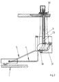
- Figure 1 shows one in a fuel tank 1 Motor vehicle mounted level sensor 2.
- the level sensor 2 has a carrier 3 for mounting two lever arms 4, 5 and for receiving a detection device 6 for the position of the lever arms 4, 5.
- a flange 7 of the Carrier 3 is in an opening 8 of a wall 9 of the Fuel tank 1 attached.
- One of the lever arms 4 carries a float 10, while the second lever arm 5 biased against the bottom of the fuel tank 1 is.
- the float 10 follows a fuel level in the fuel tank 1.
- the lever arms 4, 5 each have a lever wire 11, 12 with which they are in storage 13, 14 of the carrier 3 penetrate.
- On the lever wires 11, 12 cam discs 15, 16 are attached. Magnets are supported on the cams 15, 16 17, 18 in guides 19, 20 of the carrier 3 shifting Ram 21, 22 off.
- the magnets 17, 18 are opposed to each other Opposite polarities.
- the detection device 6 has one arranged between the two magnets 17, 18 Magnetic sensor 23.
- the magnetic sensor 23 determines the Sum of the magnetic field strengths of the magnets 17, 18 and forwards electronic signals to the outside of the Fuel contacts 1 arranged connection contacts 24th
- the electronic signals of the magnetic sensor 23 correspond thus the difference in the positions of the lever arms 4, 5 and thus with a corresponding geometric design of the cams 15, 16 of the amount of fuel in the fuel tank 1.
- the magnetic sensor 23 is in a position opposite the fuel tank 1 encapsulated recess 25 arranged.
- Within the guides 19, 20 of the magnets 17, 18 are springs 26, 27 arranged. Of course they can Magnets 17, 18 also directly and therefore without interposition the plunger 21, 22 on the cams 15, 16 issue.
- the lever wire 12 of the second lever arm 5 has in his resting on the bottom of the fuel tank 1 Area a bend 28. The bottom has in this Area of a slideway 29.
- FIG 2 shows a level sensor 30 in another Embodiment.
- This level sensor 30 differentiates differs from that of Figure 1 mainly in that the lever arms 4, 5 have magnetic cams 31, 32.
- the cams 31, 32 face each other Polarity on.
- the magnetic sensor 23 is between the Cam discs 31, 32 arranged and determines the sum the magnetic field strengths and thus the difference of the Positions of the lever arms 4, 5.
Landscapes
- Physics & Mathematics (AREA)
- Fluid Mechanics (AREA)
- General Physics & Mathematics (AREA)
- Cooling, Air Intake And Gas Exhaust, And Fuel Tank Arrangements In Propulsion Units (AREA)
- Level Indicators Using A Float (AREA)
Abstract
Description
- Fig.1
- einen erfindungsgemäßen, in einem Kraftstoff- behälter montierten Füllstandsensor,
- Fig.2
- eine weitere Ausführungsform des erfindungs- gemäßen Füllstandsensors.
Claims (11)
- Füllstandsensor für einen Flüssigkeitsbehälter, insbesondere einen Kraftstoffbehälter für ein Kraftfahrzeug, mit einem einen Schwimmer tragenden Hebelarm, mit einem zur Befestigung in dem Flüssigkeitsbehälter vorgesehenen Träger zur Lagerung des Hebelarms und mit einer Erfassungseinrichtung zur Erfassung der Stellung des Schwimmers, gekennzeichnet durch einen zweiten, zur Vorspannung gegen einen Boden des Flüssigkeitsbehälters im Bereich des Schwimmers (10) vorgesehenen Hebelarm (5) und einer Erfassungseinrichtung (6) zur Ermittlung der Stellung des zweiten Hebelarms (5).
- Füllstandsensor nach Anspruch 1, dadurch gekennzeichnet, dass der zweite Hebelarm (5) zur Verstellung zumindest eines Magneten (18) gestaltet ist und dass die Erfassungseinrichtung (6) einen Magnetsensor (23) aufweist.
- Füllstandsensor nach Anspruch 1 oder 2, dadurch gekennzeichnet, dass die Erfassungseinrichtung (6) zur Ermittlung der Differenz der Auslenkungen der Hebelarme (4, 5) gestaltet ist.
- Füllstandsensor nach zumindest einem der vorhergehenden Ansprüche, dadurch gekennzeichnet, dass von den beiden Hebelarmen (4, 5) verstellbare Magnete (17, 18) jeweils einander mit entgegengesetzter Polarisation gegenüberstehen und dass zwischen dem Bewegungsbereich der Magnete (17, 18) der Magnetsensor (23) angeordnet ist.
- Füllstandsensor nach zumindest einem der vorhergehenden Ansprüche, dadurch gekennzeichnet, dass der zweite Hebelarm (5) einen zur Bildung einer Lagerachse der Lagerung (14) in dem Träger (3) abgewinkelten Hebeldraht (12) hat.
- Füllstandsensor nach zumindest einem der vorhergehenden Ansprüche, dadurch gekennzeichnet, dass der Hebeldraht (12) in seinem zur Anlage an dem Boden vorgesehenen Bereich eine Biegung (28) hat.
- Füllstandsensor nach zumindest einem der vorhergehenden Ansprüche, dadurch gekennzeichnet, dass der zweite Hebelarm (5) eine Kurvenscheibe (16) zur Verstellung des Magneten (18) aufweist.
- Füllstandsensor nach zumindest einem der vorhergehenden Ansprüche, dadurch gekennzeichnet, dass der Magnet (18) des zweiten Hebelarms (5) mittelbar oder unmittelbar gegen die Kurvenscheibe (16) vorgespannt ist.
- Füllstandsensor nach zumindest einem der vorhergehenden Ansprüche, dadurch gekennzeichnet, dass der Magnet des zweiten Hebelarms (5) als Kurvenscheibe (32) ausgebildet ist.
- Füllstandsensor nach zumindest einem der vorhergehenden Ansprüche, dadurch gekennzeichnet, dass der Träger (3) einen in einer Öffnung (8) des Kraftstoffbehälters (1) einsetzbaren Flansch (7) und jeweils Führungen (19, 20) für die Magnete (17, 18) der Hebelarme (4, 5) und eine gegenüber dem Kraftstoffbehälter (1) abgedichtete Ausnehmung (25) zur Aufnahme des Magnetsensors (23) aufweist.
- Füllstandsensor nach zumindest einem der vorhergehenden Ansprüche, dadurch gekennzeichnet, dass der Hebeldraht (11, 12) im Bereich der Kurvenscheibe (15, 16, 31, 32) eine Abwinklung aufweist und dass die Kurvenscheibe (15, 16, 31, 32) mit dem Hebeldraht (11, 12) verklipst ist.
Applications Claiming Priority (2)
| Application Number | Priority Date | Filing Date | Title |
|---|---|---|---|
| DE10019666 | 2000-04-19 | ||
| DE10019666A DE10019666A1 (de) | 2000-04-19 | 2000-04-19 | Füllstandssensor |
Publications (2)
| Publication Number | Publication Date |
|---|---|
| EP1148319A2 true EP1148319A2 (de) | 2001-10-24 |
| EP1148319A3 EP1148319A3 (de) | 2002-03-06 |
Family
ID=7639498
Family Applications (1)
| Application Number | Title | Priority Date | Filing Date |
|---|---|---|---|
| EP01105225A Withdrawn EP1148319A3 (de) | 2000-04-19 | 2001-03-03 | Füllstandsensor |
Country Status (3)
| Country | Link |
|---|---|
| US (1) | US6508121B2 (de) |
| EP (1) | EP1148319A3 (de) |
| DE (1) | DE10019666A1 (de) |
Cited By (1)
| Publication number | Priority date | Publication date | Assignee | Title |
|---|---|---|---|---|
| EP1690068A4 (de) * | 2003-11-17 | 2007-10-17 | Nartron Corp | Kraftstoffpegelsensor |
Families Citing this family (17)
| Publication number | Priority date | Publication date | Assignee | Title |
|---|---|---|---|---|
| US6990862B2 (en) * | 2002-02-26 | 2006-01-31 | Rudolph Bergsma Trust | Hermetic fuel level sender having tank bottom referencing |
| JP4112971B2 (ja) * | 2002-12-27 | 2008-07-02 | 株式会社日立製作所 | 燃料供給装置 |
| US20040261525A1 (en) * | 2003-06-24 | 2004-12-30 | Jack Chen | Device for measuring the volume of fluid in a tank |
| US7165450B2 (en) * | 2004-07-01 | 2007-01-23 | Mohammad Ali Jamnia | Variable position sensor employing magnetic flux and housing therefore |
| EP1628115A1 (de) | 2004-08-16 | 2006-02-22 | Key Safety Systems, Inc. | Magnetisches Fühlersystem |
| US7204143B1 (en) * | 2005-09-20 | 2007-04-17 | Delaware Capital Formation, Inc. | Liquid level controller |
| GB2467661B (en) | 2007-09-20 | 2013-02-13 | Bradley Fixtures Corp | Lavatory system |
| US8424381B1 (en) | 2009-06-05 | 2013-04-23 | Liquid Measurement Systems, Inc. | Fluid level measuring device |
| WO2011044247A1 (en) | 2009-10-07 | 2011-04-14 | Bradley Fixtures Corporation | Lavatory system with hand dryer |
| US9267736B2 (en) | 2011-04-18 | 2016-02-23 | Bradley Fixtures Corporation | Hand dryer with point of ingress dependent air delay and filter sensor |
| US9170148B2 (en) | 2011-04-18 | 2015-10-27 | Bradley Fixtures Corporation | Soap dispenser having fluid level sensor |
| EP2589507A1 (de) * | 2011-11-07 | 2013-05-08 | Inergy Automotive Systems Research (Société Anonyme) | Eichmethode für einen Kraftstoffbehälter aus Plastik eines Hybridfahrzeugs |
| CA2873015C (en) | 2012-03-21 | 2018-11-13 | Bradley Fixtures Corporation | Basin and hand drying system |
| US10100501B2 (en) | 2012-08-24 | 2018-10-16 | Bradley Fixtures Corporation | Multi-purpose hand washing station |
| US11015329B2 (en) | 2016-06-08 | 2021-05-25 | Bradley Corporation | Lavatory drain system |
| US10041236B2 (en) | 2016-06-08 | 2018-08-07 | Bradley Corporation | Multi-function fixture for a lavatory system |
| DE102016222849B4 (de) * | 2016-11-21 | 2024-03-14 | Audi Ag | Verfahren zur Kalibrierung einer Anzeige eines Füllstands |
Family Cites Families (15)
| Publication number | Priority date | Publication date | Assignee | Title |
|---|---|---|---|---|
| US1902933A (en) * | 1930-09-29 | 1933-03-28 | Ac Spark Plug Co | Electric gasoline gauge |
| US3348413A (en) * | 1964-12-10 | 1967-10-24 | Gen Motors Corp | Linear fuel level gauge means |
| US3449955A (en) * | 1967-03-24 | 1969-06-17 | Chrysler Corp | Fuel level sending unit |
| US3925747A (en) * | 1974-10-11 | 1975-12-09 | Ford Motor Co | Fuel sender mechanism for a motor vehicle |
| US4107998A (en) * | 1975-04-30 | 1978-08-22 | Stewart-Warner Corporation | Petrol tank gauges |
| US3968896A (en) * | 1975-06-20 | 1976-07-13 | General Motors Corporation | Fuel tank |
| US4481389A (en) * | 1982-08-02 | 1984-11-06 | Liquid Level Lectronics, Inc. | Magnetic control device |
| DE3310704C2 (de) * | 1983-03-24 | 1989-03-16 | Audi AG, 8070 Ingolstadt | Flüssigkeitsstandmesseinrichtung |
| US4928526A (en) * | 1988-11-29 | 1990-05-29 | Stewart Warner Instrument Corporation | Universal fuel sender |
| US4939932A (en) * | 1989-03-28 | 1990-07-10 | Vdo Adolf Schindling Ag | Level measuring device |
| DE4035321A1 (de) * | 1989-11-16 | 1991-05-23 | Volkswagen Ag | Fuellstandsmesseinrichtung fuer einen fluessigkeitsbehaelter, insbesondere den kraftstoffbehaelter eines kraftfahrzeugs |
| JP2548427Y2 (ja) * | 1991-03-07 | 1997-09-24 | 富士重工業株式会社 | 自動車用合成樹脂製燃料タンクの底面基準式液位検出装置 |
| US5272918A (en) * | 1993-06-30 | 1993-12-28 | Ford Motor Company | Pivotal liquid level sensor assembly |
| GB2293013A (en) * | 1994-08-27 | 1996-03-13 | Ford Motor Co | Liquid level sender device |
| US6000913A (en) * | 1998-08-24 | 1999-12-14 | Ford Motor Company | Low profile fuel delivery module |
-
2000
- 2000-04-19 DE DE10019666A patent/DE10019666A1/de not_active Withdrawn
-
2001
- 2001-03-03 EP EP01105225A patent/EP1148319A3/de not_active Withdrawn
- 2001-03-20 US US09/813,403 patent/US6508121B2/en not_active Expired - Fee Related
Cited By (1)
| Publication number | Priority date | Publication date | Assignee | Title |
|---|---|---|---|---|
| EP1690068A4 (de) * | 2003-11-17 | 2007-10-17 | Nartron Corp | Kraftstoffpegelsensor |
Also Published As
| Publication number | Publication date |
|---|---|
| US6508121B2 (en) | 2003-01-21 |
| EP1148319A3 (de) | 2002-03-06 |
| DE10019666A1 (de) | 2001-10-25 |
| US20010032507A1 (en) | 2001-10-25 |
Similar Documents
| Publication | Publication Date | Title |
|---|---|---|
| EP1148319A2 (de) | Füllstandsensor mit einer Stellungserfassungseinrichting | |
| EP1656268B1 (de) | Kugelgelenk mit schwenkwinkelsensor | |
| EP1503912B1 (de) | Gummilager mit einfederungssensor | |
| DE69003019T2 (de) | Kraftstoffniveaumessvorrichtung in einem Behälter eines Kraftfahrzeuges. | |
| EP2304274B1 (de) | Verfahren zum kalibrieren eines positionssensors in einem kraftfahrzeuggetriebe | |
| DE69019897T2 (de) | Flüssigkeits-Messschwimmer und Schwimmergestänge. | |
| DE19842336C2 (de) | Kraftstoffbehälter für ein Kraftfahrzeug | |
| EP3308056B1 (de) | Vorrichtung zur erfassung der position eines fahrstufenwählhebels, kraftfahrzeug | |
| EP1085304A1 (de) | Füllstandssensor | |
| DE102007008155A1 (de) | Vorrichtung zur Erfassung von Relativbewegungen von Fahrwerkskomponenten | |
| WO2000063650A1 (de) | Messvorrichtung zur berührungslosen erfassung eines drehwinkels | |
| EP1312898B1 (de) | Berührungslose Füllstandssensorik | |
| DE10101174B4 (de) | Sensorvorrichtung zur Ermittlung eines Lenkwinkels und eines Lenkmoments | |
| DE3730900C2 (de) | Antrieb für Wischeranlagen an Kraftfahrzeugen | |
| DE102008053197A1 (de) | Sensorschalteinheit | |
| EP1452832B1 (de) | Magnetisch passiver Positions-Sensor, Verfahren zur Fertigung des magnetisch passiven Positions-Sensors | |
| DE102016218029A1 (de) | Kugelgelenk für ein Fahrzeug | |
| DE19956143B4 (de) | Zur Montage in einem Kraftstoffbehälter vorgesehene Fördereinrichtung | |
| EP1732781B1 (de) | Verbindungselement zur positionierung einer magnetfeldsensorik | |
| EP1613931A2 (de) | Füllstandssensor für einen kraftstoffbehälter | |
| DE4033885A1 (de) | Beschleunigungssensor | |
| DE102017128509A1 (de) | Gekapselter Magnetpositionsschalter | |
| DE102009032558A1 (de) | Schalteinheit eines Kraftfahrzeugschaltgetriebes | |
| EP0726449B1 (de) | Tragbare Messvorrichtung zur Gewichtsbestimmung von Fahrzeugen | |
| DE102024210206B3 (de) | Kugelgelenk |
Legal Events
| Date | Code | Title | Description |
|---|---|---|---|
| PUAI | Public reference made under article 153(3) epc to a published international application that has entered the european phase |
Free format text: ORIGINAL CODE: 0009012 |
|
| AK | Designated contracting states |
Kind code of ref document: A2 Designated state(s): DE ES FR GB SE Kind code of ref document: A2 Designated state(s): AT BE CH CY DE DK ES FI FR GB GR IE IT LI LU MC NL PT SE TR |
|
| AX | Request for extension of the european patent |
Free format text: AL;LT;LV;MK;RO;SI |
|
| RAP1 | Party data changed (applicant data changed or rights of an application transferred) |
Owner name: SIEMENS AKTIENGESELLSCHAFT |
|
| PUAL | Search report despatched |
Free format text: ORIGINAL CODE: 0009013 |
|
| AK | Designated contracting states |
Kind code of ref document: A3 Designated state(s): AT BE CH CY DE DK ES FI FR GB GR IE IT LI LU MC NL PT SE TR |
|
| AX | Request for extension of the european patent |
Free format text: AL;LT;LV;MK;RO;SI |
|
| 17P | Request for examination filed |
Effective date: 20020204 |
|
| AKX | Designation fees paid |
Free format text: DE ES FR GB SE |
|
| 17Q | First examination report despatched |
Effective date: 20070430 |
|
| STAA | Information on the status of an ep patent application or granted ep patent |
Free format text: STATUS: THE APPLICATION IS DEEMED TO BE WITHDRAWN |
|
| 18D | Application deemed to be withdrawn |
Effective date: 20070910 |