EP1148189A1 - Electromagnetic actuated locking mechanism - Google Patents
Electromagnetic actuated locking mechanism Download PDFInfo
- Publication number
- EP1148189A1 EP1148189A1 EP01105194A EP01105194A EP1148189A1 EP 1148189 A1 EP1148189 A1 EP 1148189A1 EP 01105194 A EP01105194 A EP 01105194A EP 01105194 A EP01105194 A EP 01105194A EP 1148189 A1 EP1148189 A1 EP 1148189A1
- Authority
- EP
- European Patent Office
- Prior art keywords
- core
- locking mechanism
- locking
- mechanism according
- electromagnet
- Prior art date
- Legal status (The legal status is an assumption and is not a legal conclusion. Google has not performed a legal analysis and makes no representation as to the accuracy of the status listed.)
- Granted
Links
Images


Classifications
-
- E—FIXED CONSTRUCTIONS
- E05—LOCKS; KEYS; WINDOW OR DOOR FITTINGS; SAFES
- E05B—LOCKS; ACCESSORIES THEREFOR; HANDCUFFS
- E05B47/00—Operating or controlling locks or other fastening devices by electric or magnetic means
- E05B47/06—Controlling mechanically-operated bolts by electro-magnetically-operated detents
- E05B47/0611—Cylinder locks with electromagnetic control
- E05B47/0638—Cylinder locks with electromagnetic control by disconnecting the rotor
- E05B47/0642—Cylinder locks with electromagnetic control by disconnecting the rotor axially, i.e. with an axially disengaging coupling element
-
- E—FIXED CONSTRUCTIONS
- E05—LOCKS; KEYS; WINDOW OR DOOR FITTINGS; SAFES
- E05B—LOCKS; ACCESSORIES THEREFOR; HANDCUFFS
- E05B47/00—Operating or controlling locks or other fastening devices by electric or magnetic means
- E05B2047/0082—Induction for charging or current transformation
-
- E—FIXED CONSTRUCTIONS
- E05—LOCKS; KEYS; WINDOW OR DOOR FITTINGS; SAFES
- E05B—LOCKS; ACCESSORIES THEREFOR; HANDCUFFS
- E05B47/00—Operating or controlling locks or other fastening devices by electric or magnetic means
-
- E—FIXED CONSTRUCTIONS
- E05—LOCKS; KEYS; WINDOW OR DOOR FITTINGS; SAFES
- E05B—LOCKS; ACCESSORIES THEREFOR; HANDCUFFS
- E05B47/00—Operating or controlling locks or other fastening devices by electric or magnetic means
- E05B47/0001—Operating or controlling locks or other fastening devices by electric or magnetic means with electric actuators; Constructional features thereof
- E05B47/0002—Operating or controlling locks or other fastening devices by electric or magnetic means with electric actuators; Constructional features thereof with electromagnets
- E05B47/0006—Operating or controlling locks or other fastening devices by electric or magnetic means with electric actuators; Constructional features thereof with electromagnets having a non-movable core; with permanent magnet
-
- G—PHYSICS
- G07—CHECKING-DEVICES
- G07C—TIME OR ATTENDANCE REGISTERS; REGISTERING OR INDICATING THE WORKING OF MACHINES; GENERATING RANDOM NUMBERS; VOTING OR LOTTERY APPARATUS; ARRANGEMENTS, SYSTEMS OR APPARATUS FOR CHECKING NOT PROVIDED FOR ELSEWHERE
- G07C9/00—Individual registration on entry or exit
- G07C9/00174—Electronically operated locks; Circuits therefor; Nonmechanical keys therefor, e.g. passive or active electrical keys or other data carriers without mechanical keys
- G07C2009/00634—Power supply for the lock
- G07C2009/00642—Power supply for the lock by battery
-
- G—PHYSICS
- G07—CHECKING-DEVICES
- G07C—TIME OR ATTENDANCE REGISTERS; REGISTERING OR INDICATING THE WORKING OF MACHINES; GENERATING RANDOM NUMBERS; VOTING OR LOTTERY APPARATUS; ARRANGEMENTS, SYSTEMS OR APPARATUS FOR CHECKING NOT PROVIDED FOR ELSEWHERE
- G07C9/00—Individual registration on entry or exit
- G07C9/00174—Electronically operated locks; Circuits therefor; Nonmechanical keys therefor, e.g. passive or active electrical keys or other data carriers without mechanical keys
- G07C2009/00753—Electronically operated locks; Circuits therefor; Nonmechanical keys therefor, e.g. passive or active electrical keys or other data carriers without mechanical keys operated by active electrical keys
- G07C2009/00769—Electronically operated locks; Circuits therefor; Nonmechanical keys therefor, e.g. passive or active electrical keys or other data carriers without mechanical keys operated by active electrical keys with data transmission performed by wireless means
- G07C2009/00793—Electronically operated locks; Circuits therefor; Nonmechanical keys therefor, e.g. passive or active electrical keys or other data carriers without mechanical keys operated by active electrical keys with data transmission performed by wireless means by Hertzian waves
-
- G—PHYSICS
- G07—CHECKING-DEVICES
- G07C—TIME OR ATTENDANCE REGISTERS; REGISTERING OR INDICATING THE WORKING OF MACHINES; GENERATING RANDOM NUMBERS; VOTING OR LOTTERY APPARATUS; ARRANGEMENTS, SYSTEMS OR APPARATUS FOR CHECKING NOT PROVIDED FOR ELSEWHERE
- G07C9/00—Individual registration on entry or exit
- G07C9/00174—Electronically operated locks; Circuits therefor; Nonmechanical keys therefor, e.g. passive or active electrical keys or other data carriers without mechanical keys
- G07C2009/00968—Electronically operated locks; Circuits therefor; Nonmechanical keys therefor, e.g. passive or active electrical keys or other data carriers without mechanical keys shape of the data carrier
- G07C2009/00992—Electronically operated locks; Circuits therefor; Nonmechanical keys therefor, e.g. passive or active electrical keys or other data carriers without mechanical keys shape of the data carrier mechanical key
-
- G—PHYSICS
- G07—CHECKING-DEVICES
- G07C—TIME OR ATTENDANCE REGISTERS; REGISTERING OR INDICATING THE WORKING OF MACHINES; GENERATING RANDOM NUMBERS; VOTING OR LOTTERY APPARATUS; ARRANGEMENTS, SYSTEMS OR APPARATUS FOR CHECKING NOT PROVIDED FOR ELSEWHERE
- G07C9/00—Individual registration on entry or exit
- G07C9/00174—Electronically operated locks; Circuits therefor; Nonmechanical keys therefor, e.g. passive or active electrical keys or other data carriers without mechanical keys
- G07C9/00182—Electronically operated locks; Circuits therefor; Nonmechanical keys therefor, e.g. passive or active electrical keys or other data carriers without mechanical keys operated with unidirectional data transmission between data carrier and locks
Definitions
- the invention relates to an electromagnetically activatable Locking mechanism, especially for a lock cylinder a mortise lock for optional blocking or release one arranged in a housing movable core, with a structural unit with an anchor, in the path of movement of the core feasible locking bolt, with an open position to the bracket of the anchor in one movement of the core the electromagnet designed to release the locking bolt, with a in the locked position for biasing the Locking bolt in a block the movement of the core Position designed locking spring and with control electronics to control the electromagnet.
- Such locking mechanisms are particularly common in modern Access control systems for buildings are often used and are known for example from EP 0 600 194 B1.
- This document describes a locking cylinder with next to arranged the electromagnetically activatable locking mechanism, mechanical pin tumblers.
- a key for turning the core has a data memory, which at Insert the key into the lock cylinder from the Control electronics is read out.
- a control center controls the electromagnet depending on the read out Data. Moved when activated by the control center the electromagnet the pin-shaped locking bolt from a position locking the core to the housing against the force of the locking spring in a rotation of the Kern's enabling position.
- This locking mechanism requires a high level of cabling for each individual Lock cylinder and high power consumption at the Movement of the locking bolt.
- the control electronics constantly on standby, leading to another Contributes to increasing electricity consumption.
- the invention is based on the problem of an electromagnetic activatable locking mechanism of the input mentioned kind so that he is a special enables simple activation of the control electronics and is as simple as possible.
- this problem is solved by the detection an electromagnetic pulse of the electromagnet when inserting a key or movement caused by the initial rotation of the core the locking bolt and by activating the control electronics by means of the impulse.
- This impulse comes by arranging such electromagnets always have a certain remanence, if this not deliberately suppressed by special precautions becomes. As a result of this remanence, it occurs in external Actions to an induction, which according to the invention as Wake-up pulse is used.
- control electronics can be switched off and thus be without power consumption if none Key inserted into the locking channel or the core is not rotated. This will make the control electronics automatically activated when using the locking mechanism. Constant electricity consumption when ready the control electronics is avoided.
- the invention Locking mechanism has a special low power consumption. The control electronics needed no switch to activate them. Because the electromagnet and the locking bolt are present anyway the locking mechanism according to the invention no additional components to be assembled and is therefore special simply set up. With a knob cylinder can be activated the control electronics instead of inserting the The knob can also be moved slightly axially.
- Electromagnet formed by an additional magnetic field arranged permanent magnet is reinforced.
- the impulse measurable threshold value for the control electronics more clearly exceeds.
- the pulse of the electromagnet is according to an advantageous one Further development of the invention can be clearly grasped, if the anchor when inserting the key or when initially rotating the core of one of the electromagnets spaced position in a on the electromagnet adjacent position is movable. Through the The impulses become clearly detectable the control unit, for example, by external Magnetic fields are largely avoided. Farther can with this design the electromagnet Control by the control electronics the anchor in its adjacent position and thus the locking bolt in one hold the position allowing the core to rotate. In order to the anchor must be in contrast to the known locking mechanism from the electromagnet not against the force the locking spring are moved. This contributes in comparison the known locking mechanism to a significant reduction of electricity consumption.
- the locking mechanism according to the invention is constructive particularly easy when the core is in one Has recess protruding recess, when the locking bar rests on the displacement element or is made in one piece with this and if the displacement element when inserting a key into one Locking channel of the core is designed to be movable.
- the recess can be, for example, the closing channel act.
- the one generated when the key was inserted Movement of the locking bolt can be very large.
- the displacement element is advantageous according to another Development of the invention against pollution and Damage caused by the one to be inserted into the locking cylinder Keys protected particularly reliably when the displacement element in a itself to the locking channel subsequent recess of the core penetrates and when a movable by a key that can be inserted into the locking channel Actuator for moving the displacement element is designed.
- the locking mechanism according to the invention requires a special one small number of components to be assembled, if the core is provided with a fillet for receiving a Has section of the free end of the locking bolt.
- the displacement element is designed according to another advantageous development of the invention particularly inexpensive if it is designed as a ball.
- the locking mechanism according to the invention requires a special one small number of components to be assembled, if the actuator has a sliding pot with a Displacement element has opposite chamfer.
- the locking mechanism according to the invention is suitable for two opposing control elements for arrangement in a locking cylinder that can be unlocked from both sides.
- control element or the control elements are according to one other advantageous development of the invention reliably held in their intended position and against guided the displacement element when the actuator or the adjusting elements are axially displaceable on a sleeve are led.
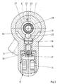
- Figure 1 shows an unlockable from two sides Lock cylinder with a housing 1 and rotatable therein arranged core 2.
- the core 2 has in its middle Area a lock bit 3 and in each end a closing channel 4, 5 for introducing a in figure 2b shown key 6.
- the locking channels 4, 5 have a round cross-section.
- To transfer a Rotary movement of the key 6 on the core 2 are on the end faces of the core 2 each driver 7, 8 arranged.
- the drivers 7, 8 are used to generate a Form fit with a not shown Reide of Key 6.
- the lock cylinder has an electronic activatable locking mechanism, each close to End faces of the housing 1 arranged code receivers 9, 10 and with a locking device 13.
- the code receiver 9, 10 detect signals from transponders 11 of the key 6 and route this to control electronics 12.
- Die Control electronics 12 determined from the signals of the transponder 11 whether the key 6 is authorized to Unlock the lock cylinder. If you have authorization the control electronics 12 controls the locking device 13 on.
- the locking device 13 has an electromagnet 14 and one of a locking spring 15 in the direction of core 2 prestressed locking bolt 16.
- the locking bolt 16 is opposite to the electromagnet 14 Anchor 17 manufactured as a structural unit.
- a battery 18 is arranged in the housing 1.
- the locking device 13 is constructed symmetrically and has a slide 19 for transmitting an axial Movement of an inserted in the right closing channel 5 Key.
- FIG. 2a shows the locking device 13 in a greatly enlarged manner from FIG. 1 with a displacement element holding the locking bolt 16 20.
- the displacement element 20 is there formed as a ball and holds the locking bolt 16 in one Position in which the armature 17 a distance from the electromagnet 14 has.
- the locking device 13 has two actuating elements 21 arranged opposite one another, 22 each with a sliding pot guided on a sleeve 23 24, 25.
- the sliding pots 24, 25 are the displacement element 20 with a chamfer 26, 27 opposite.
- Within the sleeve 23 is a spring 28 for biasing of the sliding pots 24, 25 from the displacement element 20 arranged against circumferential stops 29, 30 of the core 2.
- the sliding pots 24, 25 and the core 2 are in the Area of the locking device 13 by means of O-rings 31, 32 sealed.
- the electromagnet 14 is shown in FIG. 2a Position of the locking device 13 de-energized and the control electronics 12 deactivated.
- the corresponding Actuator 21, 22 from the front end of the shaft of the key 6 or from the slider 19 on each other actuator 21, 22 moves and the displacement element 20 pressed down. This will lock the latch 16 with the armature 17 against the electromagnet 14 emotional.
- Figure 3 shows the lock cylinder with the locking mechanism from Figure 1 in a cross section along the line III - III. It can be seen here that the locking troughs 33, 34 arranged on both sides of the displacement element 20 are. Furthermore, the locking bolt is in the drawing 16 shown in section.
- the locking bolt 16 is hollow inside and slightly pivotable and axially displaceably connected to the armature 17.
- the locking bolt 16 and the armature 17 are also provided with a spring 35 stretched away from each other. This design serves to compensate for tolerances and ensures an even installation of the anchor 17 on the electromagnet 14 safe and prevented a clamping of the locking bolt 16 in the case of the electromagnet 14 tightened anchor 17.
- FIG 4 shows a further embodiment of the invention Locking mechanism in cross section.
- the core 36 rotatable in the housing 1 between two locking troughs 37, 38 a groove 39 for receiving a provided Section of the free end of the locking bolt 16.
- the Armature 17 comes against the electromagnet 14.
- the electromagnet 14 generates a pulse Activation of the control electronics shown in Figure 1 12.
- the function and operation of the electromagnet 14 is like in the embodiment of Figure 1 to 3 described.
- To reinforce the electromagnet 14 generated pulse is also at the bottom Permanent magnet 40 arranged, through which the remanence generated magnetic field to a certain minimum field strength is increased.
Abstract
Description
Die Erfindung betrifft einen elektromagnetisch aktivierbaren Sperrmechanismus, insbesondere für einen Schließzylinder eines Einsteckschlosses zum wahlweisen Blockieren oder Freigeben eines in einem Gehäuse angeordneten beweglichen Kerns, mit einem eine bauliche Einheit mit einem Anker bildenden, in die Bewegungsbahn des Kerns führbaren Sperriegel, mit einem in Offenstellung zur Halterung des Ankers in einer eine Bewegung des Kerns durch den Sperriegel freigebenden Stellung gestalteten Elektromagneten, mit einer in Sperrstellung zur Vorspannung des Sperriegels in eine die Bewegung des Kerns blockierende Stellung gestalteten Sperrfeder und mit einer Steuerelektronik zur Ansteuerung des Elektromagneten.The invention relates to an electromagnetically activatable Locking mechanism, especially for a lock cylinder a mortise lock for optional blocking or release one arranged in a housing movable core, with a structural unit with an anchor, in the path of movement of the core feasible locking bolt, with an open position to the bracket of the anchor in one movement of the core the electromagnet designed to release the locking bolt, with a in the locked position for biasing the Locking bolt in a block the movement of the core Position designed locking spring and with control electronics to control the electromagnet.
Solche Sperrmechanismen werden insbesondere in modernen Zutrittskontrollanlagen von Gebäuden häufig eingesetzt und sind beispielsweise aus der EP 0 600 194 B1 bekannt. Diese Schrift beschreibt einen Schließzylinder mit neben dem elektromagnetisch aktivierbaren Sperrmechanismus angeordneten, mechanischen Stiftzuhaltungen. Ein Schlüssel zum Drehen des Kerns hat einen Datenspeicher, der beim Einführen des Schlüssels in den Schließzylinder von der Steuerelektronik ausgelesen wird. Eine Zentrale steuert den Elektromagneten in Abhängigkeit von den ausgelesenen Daten an. Bei einer Ansteuerung durch die Zentrale bewegt der Elektromagnet den stiftförmig gestalteten Sperriegel von einer den Kern mit dem Gehäuse verriegelnden Stellung gegen die Kraft der Sperrfeder in eine die Drehung des Kerns ermöglichende Stellung. Dieser Sperrmechanismus erfordert einen hohen Verkabelungsaufwand jedes einzelnen Schließzylinders und einen hohen Stromverbrauch bei der Bewegung des Sperriegels. Weiterhin ist hierbei die Steuerelektronik ständig in Bereitschaft, was zu einer weiteren Erhöhung des Stromverbrauchs beiträgt.Such locking mechanisms are particularly common in modern Access control systems for buildings are often used and are known for example from EP 0 600 194 B1. This document describes a locking cylinder with next to arranged the electromagnetically activatable locking mechanism, mechanical pin tumblers. A key for turning the core has a data memory, which at Insert the key into the lock cylinder from the Control electronics is read out. A control center controls the electromagnet depending on the read out Data. Moved when activated by the control center the electromagnet the pin-shaped locking bolt from a position locking the core to the housing against the force of the locking spring in a rotation of the Kern's enabling position. This locking mechanism requires a high level of cabling for each individual Lock cylinder and high power consumption at the Movement of the locking bolt. Furthermore, the control electronics constantly on standby, leading to another Contributes to increasing electricity consumption.
Man hat bereits daran gedacht, in dem Schließzylinder zur Verringerung des Stromverbrauchs einen beim Einführen des Schlüssels in den Schließkanal betätigbaren Schalter vorzusehen. Beim Einführen eines Schlüssels wird mittels des Schalters die Steuerelektronik aktiviert. Eine ständige Strom verbrauchende Bereitschaft der Steuerelektronik wird hierdurch vermieden. Nachteilig ist hierbei jedoch der hohe bauliche Aufwand des Schalters und die kostenintensive Fertigung des Schließzylinders durch die Anordnung und Verdrahtung des Schalters.It has already been thought of in the lock cylinder Reducing power consumption when introducing the Provide key operated switch in the locking channel. When inserting a key, the Switch activates the control electronics. A constant Electricity-consuming readiness of the control electronics is avoided. However, this is disadvantageous the high structural complexity of the switch and the cost-intensive Manufacture of the locking cylinder through the arrangement and wiring the switch.
Der Erfindung liegt das Problem zugrunde, einen elektromagnetisch aktivierbaren Sperrmechanismus der eingangs genannten Art so weiterzubilden, dass er eine besonders einfache Aktivierung der Steuerelektronik ermöglicht und möglichst einfach aufgebaut ist.The invention is based on the problem of an electromagnetic activatable locking mechanism of the input mentioned kind so that he is a special enables simple activation of the control electronics and is as simple as possible.
Dieses Problem wird erfindungsgemäß gelöst durch die Erfassung eines elektromagnetischen Impulses des Elektromagneten bei einer beim Einstecken eines Schlüssels oder beim anfänglichen Drehen des Kerns hervorgerufenen Bewegung des Sperriegels und durch eine Aktivierung der Steuerelektronik mittels des Impulses. Dieser Impuls kommt dadurch zustande, dass Anordnungen von solchen Elektromagneten stets eine gewisse Remanenz haben, wenn dies nicht durch besondere Vorkehrungen absichtlich unterdrückt wird. Infolge dieser Remanenz kommt es bei äußeren Einwirkungen zu einer Induktion, die erfindungsgemäß als Weckimpuls genutzt wird.According to the invention, this problem is solved by the detection an electromagnetic pulse of the electromagnet when inserting a key or movement caused by the initial rotation of the core the locking bolt and by activating the control electronics by means of the impulse. This impulse comes by arranging such electromagnets always have a certain remanence, if this not deliberately suppressed by special precautions becomes. As a result of this remanence, it occurs in external Actions to an induction, which according to the invention as Wake-up pulse is used.
Durch diese Gestaltung kann die Steuerelektronik abgeschaltet und damit ohne Stromverbrauch sein, wenn kein Schlüssel in den Schließkanal eingeführt oder der Kern nicht gedreht wird. Hierdurch wird die Steuerelektronik bei der Benutzung des Sperrmechanismus automatisch aktiviert. Ein ständiger Stromverbrauch bei der Bereitschaft der Steuerelektronik wird jedoch vermieden. Der erfindungsgemäße Sperrmechanismus hat damit einen besonders geringen Stromverbrauch. Die Steuerelektronik benötigt keinen Schalter zu ihrer Aktivierung. Da der Elektromagnet und der Sperriegel ohnehin vorhanden sind, erfordert der erfindungsgemäße Sperrmechanismus keine zusätzlich zu montierenden Bauteile und ist daher besonders einfach aufgebaut. Bei einem Knaufzylinder kann zur Aktivierung der Steuerelektronik anstelle des Einsteckens des Schlüssels auch der Knauf geringfügig axial bewegt werden.With this design, the control electronics can be switched off and thus be without power consumption if none Key inserted into the locking channel or the core is not rotated. This will make the control electronics automatically activated when using the locking mechanism. Constant electricity consumption when ready the control electronics is avoided. The invention Locking mechanism has a special low power consumption. The control electronics needed no switch to activate them. Because the electromagnet and the locking bolt are present anyway the locking mechanism according to the invention no additional components to be assembled and is therefore special simply set up. With a knob cylinder can be activated the control electronics instead of inserting the The knob can also be moved slightly axially.
Zur Verstärkung des Impulses ist bei einer Weiterbildung der Erfindung vorgesehen, dass das durch die Remanenz des Elektromagneten gebildete Magnetfeld durch einen zusätzlich angeordneten Dauermagneten verstärkt wird. Damit wird die Zuverlässigkeit erhöht, weil der Impuls einen für die Steuerelektronik messbaren Schwellwert deutlicher übersteigt.To strengthen the momentum is in a training the invention provided that by the remanence of Electromagnet formed by an additional magnetic field arranged permanent magnet is reinforced. In order to reliability is increased because the impulse measurable threshold value for the control electronics more clearly exceeds.
Der Impuls des Elektromagneten ist gemäß einer vorteilhaften Weiterbildung der Erfindung deutlich erfassbar, wenn der Anker beim Einstecken des Schlüssels oder beim anfänglichen Drehen des Kerns von einer von dem Elektromagneten beabstandeten Stellung in eine an dem Elektromagneten anliegende Stellung bewegbar ist. Durch die deutliche Erfassbarkeit des Impulses werden Fehlaktivierungen der Steuereinheit, die beispielsweise durch äußere Magnetfelder erzeugt werden, weitgehend vermieden. Weiterhin kann durch diese Gestaltung der Elektromagnet bei Ansteuerung durch die Steuerelektronik den Anker in seiner anliegenden Lage und damit den Sperriegel in einer die Drehung des Kerns ermöglichenden Stellung halten. Damit muß der Anker im Gegensatz zu dem bekannten Sperrmechanismus von dem Elektromagneten nicht gegen die Kraft der Sperrfeder bewegt werden. Dies trägt im Vergleich zu dem bekannten Sperrmechanismus zu einer deutlichen Verringerung des Stromverbrauchs bei. Ohne Ansteuerung wird der Sperriegel von der Sperrfeder in die den Kern blokkierende Stellung bewegt und damit der Anker von dem Elektromagneten entfernt. Der Hub des Sperriegels beim Einführen des Schlüssels oder beim anfänglichen Drehen kann zudem sehr groß bemessen werden, so dass der Sperrriegel bei jeder Drehung des Kerns auch bei angesteuertem Elektromagneten bewegt wird. Hierdurch wird ein durch Einrosten oder Festkleben hervorgerufenes Klemmen des Sperriegels weitgehend vermieden. Durch den großen Hub des Sperriegels wird zudem die sichere Erzeugung des Impulses gewährleistet.The pulse of the electromagnet is according to an advantageous one Further development of the invention can be clearly grasped, if the anchor when inserting the key or when initially rotating the core of one of the electromagnets spaced position in a on the electromagnet adjacent position is movable. Through the The impulses become clearly detectable the control unit, for example, by external Magnetic fields are largely avoided. Farther can with this design the electromagnet Control by the control electronics the anchor in its adjacent position and thus the locking bolt in one hold the position allowing the core to rotate. In order to the anchor must be in contrast to the known locking mechanism from the electromagnet not against the force the locking spring are moved. This contributes in comparison the known locking mechanism to a significant reduction of electricity consumption. Without control the locking bolt from the locking spring into the one blocking the core Position moves and thus the anchor of that Electromagnet removed. The stroke of the locking bolt at Insert the key or when initially turning can also be very large, so that the locking bolt with every rotation of the core, even when the Electromagnet is moved. This is a through Rusting or sticking caused jamming of the Barrier bar largely avoided. Due to the large stroke the locking bolt is also the safe generation of the pulse guaranteed.
Der erfindungsgemäße Sperrmechanismus gestaltet sich konstruktiv besonders einfach, wenn der Kern ein in eine Ausnehmung hineinragendes Verdrängungselement aufweist, wenn der Sperriegel an dem Verdrängungselement anliegt oder mit diesem einteilig gefertigt ist und wenn das Verdrängungselement beim Einführen eines Schlüssels in einen Schließkanal des Kerns bewegbar gestaltet ist. Bei der Ausnehmung kann es sich beispielsweise um den Schließkanal handeln. Die beim Einführen des Schlüssels erzeugte Bewegung des Sperriegels läßt sich hierbei sehr groß bemessen.The locking mechanism according to the invention is constructive particularly easy when the core is in one Has recess protruding recess, when the locking bar rests on the displacement element or is made in one piece with this and if the displacement element when inserting a key into one Locking channel of the core is designed to be movable. In the The recess can be, for example, the closing channel act. The one generated when the key was inserted Movement of the locking bolt can be very large.
Das Verdrängungselement ist gemäß einer anderen vorteilhaften Weiterbildung der Erfindung vor Verschmutzung und Beschädigung durch den in den Schließzylinder einzuführenden Schlüssel besonders zuverlässig geschützt, wenn das Verdrängungselement in eine sich an den Schließkanal anschließende Ausnehmung des Kerns eindringt und wenn ein von einem in den Schließkanal einführbaren Schlüssel bewegbares Stellelement zur Bewegung des Verdrängungselementes gestaltet ist.The displacement element is advantageous according to another Development of the invention against pollution and Damage caused by the one to be inserted into the locking cylinder Keys protected particularly reliably when the displacement element in a itself to the locking channel subsequent recess of the core penetrates and when a movable by a key that can be inserted into the locking channel Actuator for moving the displacement element is designed.
Der erfindungsgemäße Sperrmechanismus erfordert eine besonders geringe Anzahl von zu montierenden Bauteilen, wenn der Kern eine Hohlkehle zur Aufnahme eines vorgesehenen Abschnittes des freien Endes des Sperriegels hat.The locking mechanism according to the invention requires a special one small number of components to be assembled, if the core is provided with a fillet for receiving a Has section of the free end of the locking bolt.
Das Verdrängungselement gestaltet sich gemäß einer anderen vorteilhaften Weiterbildung der Erfindung besonders kostengünstig, wenn es als Kugel ausgebildet ist.The displacement element is designed according to another advantageous development of the invention particularly inexpensive if it is designed as a ball.
Der erfindungsgemäße Sperrmechanismus erfordert eine besonders geringe Anzahl von zu montierenden Bauteilen, wenn das Stellelement einen Schiebetopf mit einer dem Verdrängungselement gegenüberstehenden Fase aufweist.The locking mechanism according to the invention requires a special one small number of components to be assembled, if the actuator has a sliding pot with a Displacement element has opposite chamfer.
Der erfindungsgemäße Sperrmechanismus eignet sich durch zwei einander gegenüberstehende Stellelemente zur Anordnung in einem von beiden Seiten entriegelbaren Schließzylinder.The locking mechanism according to the invention is suitable for two opposing control elements for arrangement in a locking cylinder that can be unlocked from both sides.
Das Stellelement oder die Stellelemente werden gemäß einer anderen vorteilhaften Weiterbildung der Erfindung zuverlässig in ihrer vorgesehenen Lage gehalten und gegen das Verdrängungselement geführt, wenn das Stellelement oder die Stellelemente auf einer Hülse axial verschiebbar geführt sind.The control element or the control elements are according to one other advantageous development of the invention reliably held in their intended position and against guided the displacement element when the actuator or the adjusting elements are axially displaceable on a sleeve are led.
Bei von beiden Seiten entriegelbaren Schließzylindern gestaltet sich der erfindungsgemäße Sperrmechanismus konstruktiv besonders einfach, wenn die einander gegenüberstehenden, jeweils als Schiebetöpfe ausgebildeten Stellelemente mittels einer innerhalb der Hülse angeordneten Feder auf jeweils gegen Anschläge im Kern vorgespannt sind.Designed with locking cylinders that can be unlocked from both sides the locking mechanism according to the invention constructively particularly easy if the opposing, each formed as sliding pots by means of an arranged inside the sleeve Spring biased against stops in the core are.
Eine Verschmutzung und damit ein mögliches Klemmen des Sperriegels läßt sich gemäß einer anderen vorteilhaften Weiterbildung der Erfindung einfach vermeiden, wenn die Anschläge im Kern für die Stellelemente umlaufend gestaltet sind und einen O-Ring zur Abdichtung der Stellelemente gegenüber dem Kern aufweisen. Weiterhin sind das Stellelement und die entsprechenden Anschläge im Kern hierdurch rotationssymetrisch aufgebaut und lassen sich daher besonders kostengünstig fertigen.Contamination and thus possible jamming of the Locking bar can be advantageous according to another Simply avoid further development of the invention if the Stops in the core for the control elements all around and an O-ring to seal the control elements towards the core. Furthermore, these are Control element and the corresponding stops in the core hereby constructed rotationally symmetrically and can be therefore manufacture particularly inexpensively.
Zur weiteren Verringerung der Gefahr der Verschmutzung des Sperriegels trägt es gemäß einer anderen vorteilhaften Weiterbildung der Erfindung bei, wenn der Kern gegenüber dem Gehäuse im Bereich des Sperriegels abgedichtet ist. Zur Abdichtung eignen sich insbesondere O-Ringe. To further reduce the risk of pollution of the locking bolt it carries according to another advantageous Further development of the invention when the core is opposite sealed the housing in the area of the locking bolt is. O-rings are particularly suitable for sealing.
Die Erfindung läßt zahlreiche Ausführungsformen zu. Zur weiteren Verdeutlichung ihres Grundprinzips sind zwei davon in der Zeichnung dargestellt und werden nachfolgend beschrieben. Diese zeigt in
- Fig.1
- einen Längsschnitt durch einen Schließ- zylinder mit einem erfindungsgemäßen Sperrmechanismus,
- Fig.2a
- eine stark vergrößerte Darstellung einer
Sperreinrichtung des Sperrmechanismus aus
Figur 1 - Fig.2b
- die Sperreinrichtung aus Figur 2a mit in einen Schließkanal eingeführtem Schlüssel,
- Fig.3
- einen Querschnitt durch den Schließzylinder
aus
Figur 1 entlang der Linie III - III, - Fig.4
- einen Schließzylinder im Querschnitt mit einer weiteren Ausführungsform des erfindungsgemäßen Sperrmechanismus.
- Fig. 1
- 2 shows a longitudinal section through a locking cylinder with a locking mechanism according to the invention,
- Fig.2a
- a greatly enlarged illustration of a locking device of the locking mechanism of Figure 1
- Fig.2b
- 2 the locking device from FIG. 2a with the key inserted into a locking channel,
- Fig. 3
- 2 shows a cross section through the locking cylinder from FIG. 1 along the line III-III,
- Fig. 4
- a locking cylinder in cross section with a further embodiment of the locking mechanism according to the invention.
Figur 1 zeigt einen von zwei Seiten entriegelbaren
Schließzylinder mit einem Gehäuse 1 und einem darin drehbar
angeordneten Kern 2. Der Kern 2 hat in seinem mittleren
Bereich einen Schließbart 3 und in seinen Enden jeweils
einen Schließkanal 4, 5 zum Einführen eines in Figur
2b dargestellten Schlüssels 6. Die Schließkanäle 4, 5
weisen einen runden Querschnitt auf. Zur Übertragung einer
Drehbewegung des Schlüssels 6 auf den Kern 2 sind an
den Stirnseiten des Kerns 2 jeweils Mitnehmer 7, 8 angeordnet.
Die Mitnehmer 7, 8 dienen zur Erzeugung eines
Formschlusses mit einer nicht dargestellten Reide des
Schlüssels 6. Der Schließzylinder hat einen elektronisch
aktivierbaren Sperrmechanismus mit jeweils nahe der
Stirnseiten des Gehäuses 1 angeordneten Codeempfängern 9,
10 und mit einer Sperreinrichtung 13. Die Codeempfänger
9, 10 erfassen Signale von Transpondern 11 des Schlüssels
6 und leiten diese zu einer Steuerelektronik 12. Die
Steuerelektronik 12 ermittelt aus den Signalen des Transponders
11, ob der Schlüssel 6 berechtigt ist, den
Schließzylinder zu entriegeln. Bei Vorliegen einer Berechtigung
steuert die Steuerelektronik 12 die Sperreinrichtung
13 an. Die Sperreinrichtung 13 hat einen Elektromagneten
14 und einen von einer Sperrfeder 15 in Richtung
des Kerns 2 vorgespannten Sperriegel 16. Der Sperrriegel
16 ist mit einem dem Elektromagneten 14 gegenüberstehenden
Anker 17 als bauliche Einheit gefertigt. Zur
Stromversorgung der Steuerelektronik 12 und der Sperreinrichtung
13 ist in dem Gehäuse 1 eine Batterie 18 angeordnet.
Die Sperreinrichtung 13 ist symmetrisch aufgebaut
und hat einen Schieber 19 zur Übertragung einer axialen
Bewegung eines in den rechten Schließkanal 5 eingeführten
Schlüssels.Figure 1 shows an unlockable from two sides
Lock cylinder with a
Figur 2a zeigt stark vergrößert die Sperreinrichtung 13
aus Figur 1 mit einem den Sperriegel 16 halternden Verdrängungselement
20. Das Verdrängungselement 20 ist dabei
als Kugel ausgebildet und hält den Sperriegel 16 in einer
Lage, in der der Anker 17 einen Abstand von dem Elektromagneten
14 aufweist. Die Sperreinrichtung 13 hat zwei
einander gegenüberstehend angeordnete Stellelemente 21,
22 mit jeweils einem auf einer Hülse 23 geführten Schiebetopf
24, 25. Die Schiebetöpfe 24, 25 stehen dem Verdrängungselement
20 mit einer Fase 26, 27 gegenüber. Innerhalb
der Hülse 23 ist eine Feder 28 zur Vorspannung
der Schiebetöpfe 24, 25 von dem Verdrängungselement 20
weg gegen umlaufende Anschläge 29, 30 des Kerns 2 angeordnet.
Die Schiebetöpfe 24, 25 und der Kern 2 sind im
Bereich der Sperreinrichtung 13 mittels O-Ringen 31, 32
abgedichtet.FIG. 2a shows the
Der Elektromagnet 14 ist in der in Figur 2a dargestellten
Stellung der Sperreinrichtung 13 stromlos und die Steuerelektronik
12 deaktiviert. Beim Einführen eines Schlüssels
6 in den Schließkanal 4, 5 wird das entsprechende
Stellelement 21, 22 von dem vorderen Ende des Schaftes
des Schlüssels 6 oder von dem Schieber 19 auf das jeweils
andere Stellelement 21, 22 bewegt und das Verdrängungselement
20 nach unten gedrückt. Hierdurch wird der Sperrriegel
16 mit dem Anker 17 gegen den Elektromagneten 14
bewegt.The
Diese Stellung ist in Figur 2b dargestellt. Bei der Bewegung
des Ankers 17 gegen den Elektromagneten 14 erzeugt
dieser einen Impuls, der die Steuerelektronik 12 aktiviert.
Diese empfängt nun die Signale des Transponders 11
des Schlüssels 6 und wertet sie aus. Bei einer Berechtigung
des Schlüssels 6 zum Entriegeln der Sperreinrichtung
13 wird an dem Elektromagneten 14 für eine vorgesehene
Zeitdauer eine Spannung angelegt. Hierdurch verbleibt der
Anker 17 in der eingezeichneten, an dem Elektromagneten
14 anliegenden Lage. Der Elektromagnet 14 muß daher den
Anker 17 beim Entriegeln des Sperrmechanismus nur in der
anliegenden Lage halten. Eine energieaufwendige Bewegung
des Ankers 17 durch den Elektromagneten 14 ist deshalb
nicht erforderlich. Bei fehlender Berechtigung des
Schlüssels 6 zum Entriegeln des Sperrmechanismus unterbleibt
die Ansteuerung des Elektromagneten 14, so dass
die Sperrfeder 15 den Sperriegel 16 in Richtung Kern 2
vorspannt. Bei einer Drehung des Kerns 2 ohne schließberechtigten
Schlüssel 6 gelangt der Sperriegel 16 in Figur
3 dargestellte Sperrmulden 33, 34 des Kerns 2 und blokkiert
damit dessen weitere Drehung.This position is shown in Figure 2b. When moving
the
Figur 3 zeigt den Schließzylinder mit dem Sperrmechanismus
aus Figur 1 in einem Querschnitt entlang der Linie
III - III. Hierbei ist zu erkennen, dass die Sperrmulden
33, 34 auf beiden Seiten des Verdrängungselementes 20 angeordnet
sind. Weiterhin ist in der Zeichnung der Sperrriegel
16 geschnitten dargestellt. Der Sperriegel 16 ist
innen hohl gestaltet und geringfügig verschwenkbar und
axial verschiebbar mit dem Anker 17 verbunden. Der Sperrriegel
16 und der Anker 17 sind zudem mit einer Feder 35
voneinander weggespannt. Diese Gestaltung dient dem Toleranzausgleich
und stellt eine gleichmäßige Anlage des Ankers
17 an dem Elektromagneten 14 sicher und verhindert
ein Klemmen des Sperriegels 16 bei von dem Elektromagneten
14 angezogenem Anker 17.Figure 3 shows the lock cylinder with the locking mechanism
from Figure 1 in a cross section along the line
III - III. It can be seen here that the locking
Figur 4 zeigt eine weitere Ausführungsform des erfindungsgemäßen
Sperrmechanismus im Querschnitt. Hierbei hat
der im Gehäuse 1 drehbare Kern 36 zwischen zwei Sperrmulden
37, 38 eine Hohlkehle 39 zur Aufnahme eines vorgesehenen
Abschnittes des freien Endes des Sperriegels 16.
Bei einer anfänglichen Drehung des Kerns 36 wird der
Sperriegel 16 aus der Hohlkehle 39 herausgedrückt. Der
Anker 17 gelangt anschließend gegen den Elektromagneten
14. Der Elektromagnet 14 erzeugt dabei einen Impuls zur
Aktivierung der in Figur 1 dargestellten Steuerelektronik
12. Die Funktion und die Arbeitsweise des Elektromagneten
14 ist dabei wie bei der Ausführungsform nach Figur 1 bis
3 beschrieben. Zur Verstärkung des vom Elektromagneten 14
erzeugbaren Impulses ist zusätzlich am unteren Ende ein
Dauermagnet 40 angeordnet, durch den das von der Remanenz
hervor gerufene Magnetfeld auf eine bestimmte Mindestfeldstärke
erhöht wird.Figure 4 shows a further embodiment of the invention
Locking mechanism in cross section. Here has
the core 36 rotatable in the
Claims (13)
Applications Claiming Priority (2)
| Application Number | Priority Date | Filing Date | Title |
|---|---|---|---|
| DE10020038 | 2000-04-22 | ||
| DE10020038A DE10020038A1 (en) | 2000-04-22 | 2000-04-22 | Electromagnetically activatable locking mechanism |
Publications (2)
| Publication Number | Publication Date |
|---|---|
| EP1148189A1 true EP1148189A1 (en) | 2001-10-24 |
| EP1148189B1 EP1148189B1 (en) | 2004-06-23 |
Family
ID=7639751
Family Applications (1)
| Application Number | Title | Priority Date | Filing Date |
|---|---|---|---|
| EP01105194A Expired - Lifetime EP1148189B1 (en) | 2000-04-22 | 2001-03-03 | Electromagnetic actuated locking mechanism |
Country Status (4)
| Country | Link |
|---|---|
| EP (1) | EP1148189B1 (en) |
| AT (1) | ATE269929T1 (en) |
| DE (2) | DE10020038A1 (en) |
| ES (1) | ES2222282T3 (en) |
Cited By (12)
| Publication number | Priority date | Publication date | Assignee | Title |
|---|---|---|---|---|
| EP1380714A2 (en) * | 2002-07-10 | 2004-01-14 | Aug. Winkhaus GmbH & Co. KG | Blocking device, in particular for a cylinder lock |
| EP1442949A1 (en) * | 2003-02-03 | 2004-08-04 | Ford Global Technologies, Inc. | Key block circuit |
| EP1516983A1 (en) * | 2003-09-18 | 2005-03-23 | Aug. Winkhaus GmbH & Co. KG | Lock cylinder |
| EP1323880A3 (en) * | 2001-12-21 | 2006-07-05 | Schliessanlagen GmbH Pfaffenhain | Lock cylinder, in particular for mortise lock |
| EP2287424A2 (en) | 2009-08-17 | 2011-02-23 | Aug. Winkhaus GmbH & Co. KG | Locking cylinder |
| EP2441906A2 (en) | 2010-10-15 | 2012-04-18 | Aug. Winkhaus GmbH & Co. KG | Lock cylinder |
| EP2453083A3 (en) * | 2010-11-16 | 2015-05-27 | Aug. Winkhaus GmbH & Co. KG | Electronic blocking mechanism |
| CN106939736A (en) * | 2017-04-14 | 2017-07-11 | 珠海优特物联科技有限公司 | The control method of electronic lock and electronic lock |
| EP3506216A1 (en) * | 2017-12-28 | 2019-07-03 | Netatmo | Smart lock with power saving having an electromechanical key |
| GB2575164A (en) * | 2017-05-03 | 2020-01-01 | Squire Henry & Sons | An electronic locking device |
| SE1951131A1 (en) * | 2019-10-03 | 2021-04-04 | Swedlock Ab | Electromechanical lock assembly with annular element and blocking arrangement comprising a retaining device |
| WO2022211689A1 (en) * | 2021-04-01 | 2022-10-06 | Swedlock Ab | Electromechanical lock assembly |
Families Citing this family (9)
| Publication number | Priority date | Publication date | Assignee | Title |
|---|---|---|---|---|
| DE10214465A1 (en) * | 2002-03-30 | 2003-10-09 | Winkhaus Fa August | An electromagnetically operated cylinder lock has a blocking mechanism preventing the complete rotation of the cylinder unless energised. |
| DE10334494A1 (en) * | 2003-07-29 | 2005-02-24 | Aug. Winkhaus Gmbh & Co. Kg | lock cylinder |
| DE102004034109A1 (en) * | 2004-07-15 | 2006-02-02 | Aug. Winkhaus Gmbh & Co. Kg | Electronic control device and use of a passive transponder having a key |
| DE102004039531A1 (en) | 2004-08-14 | 2006-02-23 | Aug. Winkhaus Gmbh & Co. Kg | locking mechanism |
| DE102004047980B3 (en) * | 2004-10-01 | 2006-03-16 | Schliessanlagen Gmbh Pfaffenhain | Locking mechanism operated electromagnetically e.g. for key cylinder of mortise dead lock, has housing with cylinder core for key with electromagnets loaded in housing and tappet loaded and cooperates with linked spring |
| DE102007000381A1 (en) | 2007-07-17 | 2009-01-22 | Aug. Winkhaus Gmbh & Co. Kg | Electronic locking mechanism |
| CN110593656A (en) * | 2019-09-03 | 2019-12-20 | 广东亚太天能科技股份有限公司 | Lock core separation and reunion pick-proof mechanism |
| EP4092228B1 (en) * | 2021-05-18 | 2023-08-30 | SimonsVoss Technologies GmbH | Electronic lock cylinder with sealed actuator |
| DE102022100283B3 (en) | 2022-01-07 | 2023-04-27 | DResearch Fahrzeugelektronik GmbH | Locking system for detachably connecting two components of a system |
Citations (4)
| Publication number | Priority date | Publication date | Assignee | Title |
|---|---|---|---|---|
| US4761976A (en) * | 1982-11-26 | 1988-08-09 | Bauer Kaba Ag | Lock cylinder with integrated electromagnetic locking mechanism |
| US4912460A (en) * | 1987-07-16 | 1990-03-27 | John Chu | Electrostatically activated gating mechanism |
| DE4234321A1 (en) * | 1992-10-12 | 1994-04-14 | Schreiber Hans | Electronically controlled door lock operating system - has active key transmitting pre-programmed code and fibre-optic conductors for electromagnetic latch release and manual unlocking |
| EP0600194A2 (en) * | 1992-12-02 | 1994-06-08 | Aug. Winkhaus GmbH & Co. KG | Access control system |
Family Cites Families (8)
| Publication number | Priority date | Publication date | Assignee | Title |
|---|---|---|---|---|
| DE3800414A1 (en) * | 1988-01-09 | 1989-07-20 | Bks Gmbh | LOCKING CYLINDERS, PARTICULAR PROFILE CYLINDERS, IN PARTICULAR FOR POCKET LOCKS |
| NO893527L (en) * | 1989-09-01 | 1991-03-04 | Trioving As | ELECTRONIC CONTROLLED LOADING SYSTEM. |
| DE4404914A1 (en) * | 1994-02-16 | 1995-08-17 | Winkhaus Fa August | Lock mechanism for a lock |
| DE29519546U1 (en) * | 1995-12-09 | 1996-02-01 | Ikon Praezisionstechnik | Double lock cylinder |
| EP0846820A1 (en) * | 1996-12-06 | 1998-06-10 | Siemens Aktiengesellschaft | Locking system, in particular for a motor vehicle |
| DE19706822A1 (en) * | 1997-02-21 | 1998-08-27 | Schulte Zylinderschl Gmbh | Locking device with a locking cylinder |
| DE29715137U1 (en) * | 1997-08-25 | 1997-10-09 | Kuhnke Gmbh Kg H | Locking device |
| DE19835508A1 (en) * | 1998-08-06 | 2000-02-10 | Tst Tresor Und Schlostechnik G | Locking point unit for electronic locks has guide body with locking contour with working part held in locking position by spring incorporating two locking elements, has compact design |
-
2000
- 2000-04-22 DE DE10020038A patent/DE10020038A1/en not_active Withdrawn
-
2001
- 2001-03-03 DE DE50102651T patent/DE50102651D1/en not_active Expired - Lifetime
- 2001-03-03 EP EP01105194A patent/EP1148189B1/en not_active Expired - Lifetime
- 2001-03-03 ES ES01105194T patent/ES2222282T3/en not_active Expired - Lifetime
- 2001-03-03 AT AT01105194T patent/ATE269929T1/en active
Patent Citations (4)
| Publication number | Priority date | Publication date | Assignee | Title |
|---|---|---|---|---|
| US4761976A (en) * | 1982-11-26 | 1988-08-09 | Bauer Kaba Ag | Lock cylinder with integrated electromagnetic locking mechanism |
| US4912460A (en) * | 1987-07-16 | 1990-03-27 | John Chu | Electrostatically activated gating mechanism |
| DE4234321A1 (en) * | 1992-10-12 | 1994-04-14 | Schreiber Hans | Electronically controlled door lock operating system - has active key transmitting pre-programmed code and fibre-optic conductors for electromagnetic latch release and manual unlocking |
| EP0600194A2 (en) * | 1992-12-02 | 1994-06-08 | Aug. Winkhaus GmbH & Co. KG | Access control system |
Cited By (19)
| Publication number | Priority date | Publication date | Assignee | Title |
|---|---|---|---|---|
| EP1323880A3 (en) * | 2001-12-21 | 2006-07-05 | Schliessanlagen GmbH Pfaffenhain | Lock cylinder, in particular for mortise lock |
| EP1380714A2 (en) * | 2002-07-10 | 2004-01-14 | Aug. Winkhaus GmbH & Co. KG | Blocking device, in particular for a cylinder lock |
| EP1380714A3 (en) * | 2002-07-10 | 2006-09-06 | Aug. Winkhaus GmbH & Co. KG | Blocking device, in particular for a cylinder lock |
| EP1442949A1 (en) * | 2003-02-03 | 2004-08-04 | Ford Global Technologies, Inc. | Key block circuit |
| EP1516983A1 (en) * | 2003-09-18 | 2005-03-23 | Aug. Winkhaus GmbH & Co. KG | Lock cylinder |
| EP2287424A2 (en) | 2009-08-17 | 2011-02-23 | Aug. Winkhaus GmbH & Co. KG | Locking cylinder |
| DE102009028599A1 (en) | 2009-08-17 | 2011-02-24 | Aug. Winkhaus Gmbh & Co. Kg | lock cylinder |
| DE102010042486A1 (en) | 2010-10-15 | 2012-04-19 | Aug. Winkhaus Gmbh & Co. Kg | lock cylinder |
| EP2441906A2 (en) | 2010-10-15 | 2012-04-18 | Aug. Winkhaus GmbH & Co. KG | Lock cylinder |
| EP2453083A3 (en) * | 2010-11-16 | 2015-05-27 | Aug. Winkhaus GmbH & Co. KG | Electronic blocking mechanism |
| CN106939736A (en) * | 2017-04-14 | 2017-07-11 | 珠海优特物联科技有限公司 | The control method of electronic lock and electronic lock |
| GB2575164A (en) * | 2017-05-03 | 2020-01-01 | Squire Henry & Sons | An electronic locking device |
| GB2575164B (en) * | 2017-05-03 | 2021-08-04 | Squire Henry & Sons | An electronic locking device |
| EP3506216A1 (en) * | 2017-12-28 | 2019-07-03 | Netatmo | Smart lock with power saving having an electromechanical key |
| CN110029881A (en) * | 2017-12-28 | 2019-07-19 | 尼特莫公司 | Smart lock with the motor machine key with power saving |
| SE1951131A1 (en) * | 2019-10-03 | 2021-04-04 | Swedlock Ab | Electromechanical lock assembly with annular element and blocking arrangement comprising a retaining device |
| WO2021066718A1 (en) * | 2019-10-03 | 2021-04-08 | Swedlock Ab | Electromechanical lock assembly with annular element, blocking and retaining devices |
| SE543627C2 (en) * | 2019-10-03 | 2021-04-27 | Swedlock Ab | Electromechanical lock assembly with annular element and blocking arrangement comprising a retaining device |
| WO2022211689A1 (en) * | 2021-04-01 | 2022-10-06 | Swedlock Ab | Electromechanical lock assembly |
Also Published As
| Publication number | Publication date |
|---|---|
| DE50102651D1 (en) | 2004-07-29 |
| ATE269929T1 (en) | 2004-07-15 |
| EP1148189B1 (en) | 2004-06-23 |
| DE10020038A1 (en) | 2001-10-25 |
| ES2222282T3 (en) | 2005-02-01 |
Similar Documents
| Publication | Publication Date | Title |
|---|---|---|
| EP1148189B1 (en) | Electromagnetic actuated locking mechanism | |
| DE10230344B3 (en) | Tamper-proof electromagnet assembly, electronic lock cylinder and method for preventing manipulation of a solenoid assembly | |
| EP1626142B1 (en) | Blocking mechanism | |
| EP0526904A1 (en) | Locking cylinder, especially for a mortise lock | |
| EP1443162B1 (en) | Lock cylinder | |
| CH671800A5 (en) | ||
| EP0668422B1 (en) | Locking mechanism for a lock | |
| EP0999328B1 (en) | Cylinder lock | |
| EP0368018B1 (en) | Furniture, especially for doors or the like | |
| EP1380714B1 (en) | Cylinder lock with a blocking device | |
| EP0303849B1 (en) | Locking cylinder with an electromagnetically actuated blocking element | |
| EP1022415B1 (en) | Electromagnetic actuated locking mechanism | |
| EP1022416B1 (en) | Electromagnetic actuated locking mechanism | |
| EP1505229B1 (en) | Lock cylinder | |
| EP1705321B1 (en) | Lock cylinder | |
| DE3432981A1 (en) | SIDE LOCK OF A LOCKING DEVICE FOR BURGLAR-RESISTANT DOORS | |
| EP1323880A2 (en) | Lock cylinder, in particular for mortise lock | |
| EP0644974B1 (en) | Locking system composed of a lock and several keys | |
| EP2017410B1 (en) | Electronic blocking mechanism | |
| DE19753434A1 (en) | Cylinder lock with remote locking | |
| EP3734001B1 (en) | Locking device | |
| AT312456B (en) | Locking device with key | |
| EP1170443A1 (en) | Electromotive drive for a lock | |
| EP1710376B1 (en) | Lock cylinder | |
| AT400061B (en) | Electric or electronic lock |
Legal Events
| Date | Code | Title | Description |
|---|---|---|---|
| PUAI | Public reference made under article 153(3) epc to a published international application that has entered the european phase |
Free format text: ORIGINAL CODE: 0009012 |
|
| AK | Designated contracting states |
Kind code of ref document: A1 Designated state(s): AT BE CH CY DE DK ES FI FR GB GR IE IT LI LU MC NL PT SE TR |
|
| AX | Request for extension of the european patent |
Free format text: AL;LT;LV;MK;RO;SI |
|
| 17P | Request for examination filed |
Effective date: 20020309 |
|
| AKX | Designation fees paid |
Free format text: AT BE CH CY DE DK ES FI FR GB GR IE IT LI LU MC NL PT SE TR |
|
| GRAP | Despatch of communication of intention to grant a patent |
Free format text: ORIGINAL CODE: EPIDOSNIGR1 |
|
| GRAS | Grant fee paid |
Free format text: ORIGINAL CODE: EPIDOSNIGR3 |
|
| GRAA | (expected) grant |
Free format text: ORIGINAL CODE: 0009210 |
|
| AK | Designated contracting states |
Kind code of ref document: B1 Designated state(s): AT BE CH CY DE DK ES FI FR GB GR IE IT LI LU MC NL PT SE TR |
|
| PG25 | Lapsed in a contracting state [announced via postgrant information from national office to epo] |
Ref country code: FI Free format text: LAPSE BECAUSE OF FAILURE TO SUBMIT A TRANSLATION OF THE DESCRIPTION OR TO PAY THE FEE WITHIN THE PRESCRIBED TIME-LIMIT Effective date: 20040623 Ref country code: IE Free format text: LAPSE BECAUSE OF FAILURE TO SUBMIT A TRANSLATION OF THE DESCRIPTION OR TO PAY THE FEE WITHIN THE PRESCRIBED TIME-LIMIT Effective date: 20040623 Ref country code: TR Free format text: LAPSE BECAUSE OF FAILURE TO SUBMIT A TRANSLATION OF THE DESCRIPTION OR TO PAY THE FEE WITHIN THE PRESCRIBED TIME-LIMIT Effective date: 20040623 |
|
| REG | Reference to a national code |
Ref country code: GB Ref legal event code: FG4D Free format text: NOT ENGLISH |
|
| REG | Reference to a national code |
Ref country code: CH Ref legal event code: EP |
|
| GBT | Gb: translation of ep patent filed (gb section 77(6)(a)/1977) |
Effective date: 20040623 |
|
| REG | Reference to a national code |
Ref country code: IE Ref legal event code: FG4D Free format text: GERMAN |
|
| REF | Corresponds to: |
Ref document number: 50102651 Country of ref document: DE Date of ref document: 20040729 Kind code of ref document: P |
|
| PG25 | Lapsed in a contracting state [announced via postgrant information from national office to epo] |
Ref country code: SE Free format text: LAPSE BECAUSE OF FAILURE TO SUBMIT A TRANSLATION OF THE DESCRIPTION OR TO PAY THE FEE WITHIN THE PRESCRIBED TIME-LIMIT Effective date: 20040923 Ref country code: DK Free format text: LAPSE BECAUSE OF FAILURE TO SUBMIT A TRANSLATION OF THE DESCRIPTION OR TO PAY THE FEE WITHIN THE PRESCRIBED TIME-LIMIT Effective date: 20040923 Ref country code: GR Free format text: LAPSE BECAUSE OF FAILURE TO SUBMIT A TRANSLATION OF THE DESCRIPTION OR TO PAY THE FEE WITHIN THE PRESCRIBED TIME-LIMIT Effective date: 20040923 |
|
| ET | Fr: translation filed | ||
| REG | Reference to a national code |
Ref country code: ES Ref legal event code: FG2A Ref document number: 2222282 Country of ref document: ES Kind code of ref document: T3 |
|
| PG25 | Lapsed in a contracting state [announced via postgrant information from national office to epo] |
Ref country code: LU Free format text: LAPSE BECAUSE OF NON-PAYMENT OF DUE FEES Effective date: 20050303 Ref country code: CY Free format text: LAPSE BECAUSE OF FAILURE TO SUBMIT A TRANSLATION OF THE DESCRIPTION OR TO PAY THE FEE WITHIN THE PRESCRIBED TIME-LIMIT Effective date: 20050303 |
|
| REG | Reference to a national code |
Ref country code: IE Ref legal event code: FD4D |
|
| PG25 | Lapsed in a contracting state [announced via postgrant information from national office to epo] |
Ref country code: MC Free format text: LAPSE BECAUSE OF NON-PAYMENT OF DUE FEES Effective date: 20050331 Ref country code: LI Free format text: LAPSE BECAUSE OF NON-PAYMENT OF DUE FEES Effective date: 20050331 Ref country code: CH Free format text: LAPSE BECAUSE OF NON-PAYMENT OF DUE FEES Effective date: 20050331 |
|
| PLBE | No opposition filed within time limit |
Free format text: ORIGINAL CODE: 0009261 |
|
| STAA | Information on the status of an ep patent application or granted ep patent |
Free format text: STATUS: NO OPPOSITION FILED WITHIN TIME LIMIT |
|
| 26N | No opposition filed |
Effective date: 20050324 |
|
| REG | Reference to a national code |
Ref country code: CH Ref legal event code: PL |
|
| PGFP | Annual fee paid to national office [announced via postgrant information from national office to epo] |
Ref country code: ES Payment date: 20060306 Year of fee payment: 6 |
|
| PGFP | Annual fee paid to national office [announced via postgrant information from national office to epo] |
Ref country code: FR Payment date: 20060317 Year of fee payment: 6 |
|
| PGFP | Annual fee paid to national office [announced via postgrant information from national office to epo] |
Ref country code: BE Payment date: 20060320 Year of fee payment: 6 |
|
| GBPC | Gb: european patent ceased through non-payment of renewal fee |
Effective date: 20070303 |
|
| BERE | Be: lapsed |
Owner name: AUG. *WINKHAUS G.M.B.H. & CO. K.G. Effective date: 20070331 |
|
| PG25 | Lapsed in a contracting state [announced via postgrant information from national office to epo] |
Ref country code: PT Free format text: LAPSE BECAUSE OF NON-PAYMENT OF DUE FEES Effective date: 20041123 Ref country code: BE Free format text: LAPSE BECAUSE OF NON-PAYMENT OF DUE FEES Effective date: 20070331 |
|
| REG | Reference to a national code |
Ref country code: FR Ref legal event code: ST Effective date: 20071130 |
|
| PG25 | Lapsed in a contracting state [announced via postgrant information from national office to epo] |
Ref country code: GB Free format text: LAPSE BECAUSE OF NON-PAYMENT OF DUE FEES Effective date: 20070303 |
|
| REG | Reference to a national code |
Ref country code: ES Ref legal event code: FD2A Effective date: 20070305 |
|
| PG25 | Lapsed in a contracting state [announced via postgrant information from national office to epo] |
Ref country code: ES Free format text: LAPSE BECAUSE OF NON-PAYMENT OF DUE FEES Effective date: 20070305 Ref country code: FR Free format text: LAPSE BECAUSE OF NON-PAYMENT OF DUE FEES Effective date: 20070402 |
|
| PGFP | Annual fee paid to national office [announced via postgrant information from national office to epo] |
Ref country code: GB Payment date: 20060322 Year of fee payment: 6 |
|
| PGFP | Annual fee paid to national office [announced via postgrant information from national office to epo] |
Ref country code: IT Payment date: 20100323 Year of fee payment: 10 |
|
| PG25 | Lapsed in a contracting state [announced via postgrant information from national office to epo] |
Ref country code: IT Free format text: LAPSE BECAUSE OF NON-PAYMENT OF DUE FEES Effective date: 20110303 |
|
| PGFP | Annual fee paid to national office [announced via postgrant information from national office to epo] |
Ref country code: NL Payment date: 20140324 Year of fee payment: 14 |
|
| PGFP | Annual fee paid to national office [announced via postgrant information from national office to epo] |
Ref country code: AT Payment date: 20150326 Year of fee payment: 15 |
|
| REG | Reference to a national code |
Ref country code: NL Ref legal event code: MM Effective date: 20150401 |
|
| REG | Reference to a national code |
Ref country code: AT Ref legal event code: MM01 Ref document number: 269929 Country of ref document: AT Kind code of ref document: T Effective date: 20160303 |
|
| PG25 | Lapsed in a contracting state [announced via postgrant information from national office to epo] |
Ref country code: AT Free format text: LAPSE BECAUSE OF NON-PAYMENT OF DUE FEES Effective date: 20160303 |
|
| PG25 | Lapsed in a contracting state [announced via postgrant information from national office to epo] |
Ref country code: NL Free format text: LAPSE BECAUSE OF NON-PAYMENT OF DUE FEES Effective date: 20150401 |
|
| PGFP | Annual fee paid to national office [announced via postgrant information from national office to epo] |
Ref country code: DE Payment date: 20170531 Year of fee payment: 17 |
|
| REG | Reference to a national code |
Ref country code: DE Ref legal event code: R119 Ref document number: 50102651 Country of ref document: DE |
|
| PG25 | Lapsed in a contracting state [announced via postgrant information from national office to epo] |
Ref country code: DE Free format text: LAPSE BECAUSE OF NON-PAYMENT OF DUE FEES Effective date: 20181002 |