EP1147730A1 - Cafetière expresso à deux thermostats - Google Patents
Cafetière expresso à deux thermostats Download PDFInfo
- Publication number
- EP1147730A1 EP1147730A1 EP01420088A EP01420088A EP1147730A1 EP 1147730 A1 EP1147730 A1 EP 1147730A1 EP 01420088 A EP01420088 A EP 01420088A EP 01420088 A EP01420088 A EP 01420088A EP 1147730 A1 EP1147730 A1 EP 1147730A1
- Authority
- EP
- European Patent Office
- Prior art keywords
- coffee
- thermostat
- temperature
- coffee maker
- water
- Prior art date
- Legal status (The legal status is an assumption and is not a legal conclusion. Google has not performed a legal analysis and makes no representation as to the accuracy of the status listed.)
- Granted
Links
- 235000016213 coffee Nutrition 0.000 title claims abstract description 56
- 235000013353 coffee beverage Nutrition 0.000 title claims abstract description 56
- 235000015114 espresso Nutrition 0.000 title description 2
- 238000010438 heat treatment Methods 0.000 claims abstract description 44
- XLYOFNOQVPJJNP-UHFFFAOYSA-N water Substances O XLYOFNOQVPJJNP-UHFFFAOYSA-N 0.000 claims abstract description 37
- 238000000605 extraction Methods 0.000 claims description 11
- 238000004519 manufacturing process Methods 0.000 claims description 8
- 240000007154 Coffea arabica Species 0.000 description 46
- 238000009834 vaporization Methods 0.000 description 6
- 230000008016 vaporization Effects 0.000 description 6
- 238000010586 diagram Methods 0.000 description 4
- 238000005325 percolation Methods 0.000 description 4
- 230000007423 decrease Effects 0.000 description 2
- 238000000034 method Methods 0.000 description 2
- 230000001105 regulatory effect Effects 0.000 description 2
- 239000000243 solution Substances 0.000 description 2
- 230000006978 adaptation Effects 0.000 description 1
- XAGFODPZIPBFFR-UHFFFAOYSA-N aluminium Chemical compound [Al] XAGFODPZIPBFFR-UHFFFAOYSA-N 0.000 description 1
- 229910052782 aluminium Inorganic materials 0.000 description 1
- 230000033228 biological regulation Effects 0.000 description 1
- 238000009835 boiling Methods 0.000 description 1
- 230000015556 catabolic process Effects 0.000 description 1
- 238000010276 construction Methods 0.000 description 1
- 238000005485 electric heating Methods 0.000 description 1
- 230000005611 electricity Effects 0.000 description 1
- 230000005021 gait Effects 0.000 description 1
- 238000009499 grossing Methods 0.000 description 1
- 239000008236 heating water Substances 0.000 description 1
- 235000012171 hot beverage Nutrition 0.000 description 1
- 239000003978 infusion fluid Substances 0.000 description 1
- 230000001788 irregular Effects 0.000 description 1
- 238000013021 overheating Methods 0.000 description 1
- 239000007921 spray Substances 0.000 description 1
- 238000011144 upstream manufacturing Methods 0.000 description 1
Images

Classifications
-
- A—HUMAN NECESSITIES
- A47—FURNITURE; DOMESTIC ARTICLES OR APPLIANCES; COFFEE MILLS; SPICE MILLS; SUCTION CLEANERS IN GENERAL
- A47J—KITCHEN EQUIPMENT; COFFEE MILLS; SPICE MILLS; APPARATUS FOR MAKING BEVERAGES
- A47J31/00—Apparatus for making beverages
- A47J31/44—Parts or details or accessories of beverage-making apparatus
- A47J31/54—Water boiling vessels in beverage making machines
- A47J31/56—Water boiling vessels in beverage making machines having water-level controls; having temperature controls
Definitions
- the present invention relates to pressure coffee makers of the espresso type.
- This type of coffee maker most often has a production function of steam, which is used to heat a drink.
- This hot water generator can be set to a temperature higher than that of boiling water.
- the water enters the heating body of the coffee maker and heats up in the process.
- the temperature of the heating body is adjusted to obtain good coffee temperature in the receiving cup.
- the first introduction of water in the heater actually lowers the temperature significantly before the thermostat could not respond, so successive cup coffees have insufficient or irregular temperatures.
- the object of the invention below is an economical coffee maker not having the disadvantages mentioned above.
- the object of the invention is achieved by a coffee maker having a reservoir of cold water, a pump, a heating block equipped with a first and a second thermostat, a filter, remarkable in that the second thermostat including the setpoint is higher is put into service at the same time as the pump for produce the hot water necessary for coffee.
- the invention is fully satisfied with set electromechanical thermostats inexpensive fixed.
- two thermostats simple electronic for special reasons, of size or implementation for example, without departing from the scope of the invention.
- the coffee maker is equipped with two thermostats.
- the heating block is adjusted by a first thermostat to a first temperature for example 95 ° C sufficient to bring the water to the temperature required for coffee extraction.
- a second thermostat with a higher set temperature for example 115 ° C is put into service. The difference between this temperature of setpoint and the block temperature at start-up is added to the drop in temperature of the heating block due to the passage of water. This gives a signal strong thermostat which quickly supplies electrical power of heating.
- the installed power of the coffee maker is suitable for heating the nominal flow of water for coffee at extraction temperature.
- the thermal inertia of the heating block contributes to smoothing differences in water temperature that could occur due to difference in adaptation between the heating power and the water flow. If the installed power is properly adjusted, we can even consider reduce the mass of the heating block, the thermal inertia no longer being essential. The water is thus at the right temperature for the entire duration of percolation.
- the first thermostat resumes control of the temperature of the heating block, so that when the water flow stops it does not no overheating occurs, and the coffee maker is immediately available for a new percolation.
- the coffee maker has a steam production function during which, when used, the second thermostat controls the temperature of the heating block.
- the same second thermostat is used to control the heating block during percolation and to obtain steam.
- the heating power and heat exchange conditions are insufficient opposite the water flow so that the water temperature rises to the temperature setpoint, while during steam production, the water flow from the pump is reduced so that the heating block remains at a temperature sufficient to obtain good vaporization.
- This reduction in water flow can conventionally be obtained by throttling of the steam outlet, or by a throttling of the circuit water, or by reducing the pump flow by electrical means, or by any other combination of known means.
- Reducing water flow is a simple and satisfactory solution, but any solution to obtain a sufficient ratio between electrical power and the power required to evaporate the water flow allows the application of the invention.
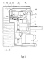
- Figure 1 is a side view of a coffee maker according to the invention, in section partial of the envelope, the tank and the heating body.
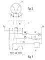
- Figure 2 is a front view of the control button.
- FIG. 3 is a block electrical diagram of the invention.
- FIG. 4 is a temperature diagram of the heating block as a function of the time before and during the extraction of a coffee.
- FIG. 5 is a temperature diagram of the heating block as a function of the time before and during steam production.
- the coffee maker has a water circuit consisting from upstream to downstream by a water tank 1, an electromagnetic pump 2, a heating body 3, a distributor 4, a support 5 and a filter holder 6 containing the ground coffee.
- the coffee is received in a receptacle 7 which can be a cup.
- the coffee maker further comprises a steam duct 9 supplied by the distributor 4 and terminated by a nozzle 10 comprising a calibrated nozzle, this under together being accessible by the user,
- the user has a command 11 acting simultaneously on the distributor 4 and on an electrical switch 12.
- the heating block 3 is an aluminum block comprising channels 31 in which the water from pump 2 heats up and eventually turns into steam.
- the electric heating element 32 supplies the energy necessary for this block, which is equipped with a first thermostat electromechanical 33 set in the vicinity of 105 ° C (t1 ° in Figures 4 and 5) and a second electromechanical thermostat 34 set to around 125 ° C (t2 ° on the Figures 4 and 5).
- the distributor 4 is capable of establishing the hydraulic connection between the block heater 3 and filter 6 to make coffee or between heater 3 and outlet of steam 9-10 when you want to heat a drink.
- This distributor is controlled by the user at the same time as the switch 12 by the button 11 which can take five positions marked P0 to P4 on the figures 3-5 and by pictograms visible in figure 2 under the button control 11.
- the control button 11 simultaneously drives sliding contacts 41 and 42 of the switch 12 so that in FIG. 3 the contacts 41, 42 align with one of the positions P0 to P4, the center lines of which are mixed line correspond to the pictograms in figure 2.
- Position 0 of the control button and P0 of the switch is the position the coffee maker.
- the electric current of the sector arrives by the identified wires L1 and L2 but no element is supplied.
- a heating indicator 35 in parallel with the heating element 32 lights up until the set temperature is reached, then turns off when the first thermostat 33 opens.
- the coffee maker thus being ready, the user orders at a time t2 the extraction of the coffee by moving the switch to position P2.
- Distributor 4 then connects the heating block 3 to the filter holder 6.
- the electric current flows from L1 to the pump 2 and via the thermostat 34 to the heating element 32 and its indicator light heats 35.
- the temperature of the heating block 3 being lower than the temperature setpoint t2 ° of thermostat 34, the heating is switched on.
- the power of the heating element 32 is substantially adjusted by construction to the power consumed by heating water.
- the water circulating by heating in the heating block 3 keeps the temperature substantially constant as is see it in solid line on the diagram of figure 4.
- the user can put the coffee maker back in position P1 waiting to extract a new coffee.
- the pump stops and the coffee maker is again regulated by thermostat 33 to the coffee extraction temperature. he therefore cannot overheat and the coffee maker is ready for new extraction.
- the user can also decide to prepare a hot drink. It positions at a time t10 the button 11 so that the switch 12 is in position P3.
- the heating element 32 is supplied with electrical energy via the thermostat 34 and the heating block 3 heats up to a water vaporization temperature.
- the setpoint temperature t2 ° of thermostat 34 reached, light 35 goes out.
- the user initiates steam production at a time t20 by supplying button 11 the switch in position P4.
- Pump 2 is supplied with electricity, the heating element 32 continues to be regulated by the thermostat 34.
- the distributor 4 connects the heating block 3 to the tube 9 which the user immerses the orifice 10 calibrated in the drink to be heated. Water vaporizes on contact with heating block 3 producing a large volume flow of steam. By the way in the calibrated orifice of nozzle 10 the vapor produces an increase of pressure, which decreases the water flow. Hence the power of the element is sufficient to maintain the vaporization temperature, ensuring a jet of continuous steam.
- the available power is therefore high compared to that which is consumed.
- the temperature of the heating block does not drop much when the vaporization and quickly returns to the set temperature t2 ° as is can see it in figure 5.
- the pump 2 includes, or is associated with, a device sequencer causing a decrease in its gait factor, which makes the easier calibration of nozzle opening 10.
- the heating element has several resistances and the power is increased during vaporization.
- the electrical circuit is modified accordingly.
- positions P3 and P4 of the switch are deleted.
- the coffee maker described has the same number of components as a coffee maker classic with a steam production function, but the arrangement of these components allows good regulation of the coffee temperature drink obtained. In a version that does not have a spray function, improvement requires only an additional inexpensive thermostat.
Landscapes
- Engineering & Computer Science (AREA)
- Food Science & Technology (AREA)
- Apparatus For Making Beverages (AREA)
Abstract
Description
Claims (3)
- Cafetière ayant un réservoir d'eau froide (1), une pompe (2), un bloc de chauffe (3) équipé d'un premier et d'un deuxième thermostat (33,34), un filtre (6), caractérisée en ce que le deuxième thermostat (34) dont la consigne est plus élevée est mis en service en même temps que la pompe (2) pour produire l'eau chaude nécessaire au café.
- Cafetière selon la revendication 1 caractérisée en ce que la puissance installée de la cafetière est adaptée à échauffer le débit nominal de l'eau destinée au café à la température d'extraction.
- Cafetière selon l'une des revendications précédentes caractérisée en ce que la cafetière comporte une fonction de production de vapeur pendant laquelle, lorsqu'elle est utilisée, le deuxième thermostat (34) contrôle la température du bloc de chauffe (3).
Applications Claiming Priority (2)
| Application Number | Priority Date | Filing Date | Title |
|---|---|---|---|
| FR0005189 | 2000-04-21 | ||
| FR0005189A FR2807930B1 (fr) | 2000-04-21 | 2000-04-21 | Cafetiere expresso a deux thermostats |
Publications (2)
| Publication Number | Publication Date |
|---|---|
| EP1147730A1 true EP1147730A1 (fr) | 2001-10-24 |
| EP1147730B1 EP1147730B1 (fr) | 2004-02-25 |
Family
ID=8849518
Family Applications (1)
| Application Number | Title | Priority Date | Filing Date |
|---|---|---|---|
| EP20010420088 Expired - Lifetime EP1147730B1 (fr) | 2000-04-21 | 2001-04-10 | Cafetière expresso à deux thermostats |
Country Status (4)
| Country | Link |
|---|---|
| EP (1) | EP1147730B1 (fr) |
| DE (1) | DE60102090T2 (fr) |
| ES (1) | ES2214389T3 (fr) |
| FR (1) | FR2807930B1 (fr) |
Cited By (4)
| Publication number | Priority date | Publication date | Assignee | Title |
|---|---|---|---|---|
| EP1369070A2 (fr) | 2002-06-05 | 2003-12-10 | Bruno Atzori | Machine à café et valve correspondante |
| US7347137B2 (en) * | 2002-06-19 | 2008-03-25 | Seb S.A. | Espresso coffeemaker with removable water reservoir |
| ITBO20100513A1 (it) * | 2010-08-06 | 2012-02-07 | Gianfranco Gozzi | Dispositivo di riscaldamento per liquidi e metodo di controllo della temperatura |
| FR3076987A1 (fr) * | 2018-01-25 | 2019-07-26 | Seb S.A. | Machine de preparation de boissons munie d'une seule pompe |
Families Citing this family (1)
| Publication number | Priority date | Publication date | Assignee | Title |
|---|---|---|---|---|
| DE102005030822A1 (de) | 2005-07-01 | 2007-01-11 | Krones Ag | Verfahren und Vorrichtung zum Überwachen eines Verdampfers |
Citations (6)
| Publication number | Priority date | Publication date | Assignee | Title |
|---|---|---|---|---|
| US4109565A (en) | 1977-04-29 | 1978-08-29 | Tucker Robert R | Coffee percolator |
| US4242568A (en) * | 1978-04-10 | 1980-12-30 | Turmix Ag | Apparatus for the selective production of hot water and steam |
| FR2465451A1 (fr) | 1979-09-25 | 1981-03-27 | Nascardi Piero | Percolateur a usage menager |
| US5337652A (en) * | 1991-07-19 | 1994-08-16 | Arthur Eugster Ag | Espresso machine |
| EP0631752A1 (fr) * | 1993-06-30 | 1995-01-04 | Eugster/Frismag AG | Machine à café express |
| FR2774882A1 (fr) | 1998-02-13 | 1999-08-20 | Seb Sa | Cafetiere electrique du type expresso a regulation thermique |
-
2000
- 2000-04-21 FR FR0005189A patent/FR2807930B1/fr not_active Expired - Fee Related
-
2001
- 2001-04-10 DE DE2001602090 patent/DE60102090T2/de not_active Expired - Lifetime
- 2001-04-10 EP EP20010420088 patent/EP1147730B1/fr not_active Expired - Lifetime
- 2001-04-10 ES ES01420088T patent/ES2214389T3/es not_active Expired - Lifetime
Patent Citations (6)
| Publication number | Priority date | Publication date | Assignee | Title |
|---|---|---|---|---|
| US4109565A (en) | 1977-04-29 | 1978-08-29 | Tucker Robert R | Coffee percolator |
| US4242568A (en) * | 1978-04-10 | 1980-12-30 | Turmix Ag | Apparatus for the selective production of hot water and steam |
| FR2465451A1 (fr) | 1979-09-25 | 1981-03-27 | Nascardi Piero | Percolateur a usage menager |
| US5337652A (en) * | 1991-07-19 | 1994-08-16 | Arthur Eugster Ag | Espresso machine |
| EP0631752A1 (fr) * | 1993-06-30 | 1995-01-04 | Eugster/Frismag AG | Machine à café express |
| FR2774882A1 (fr) | 1998-02-13 | 1999-08-20 | Seb Sa | Cafetiere electrique du type expresso a regulation thermique |
Cited By (6)
| Publication number | Priority date | Publication date | Assignee | Title |
|---|---|---|---|---|
| EP1369070A2 (fr) | 2002-06-05 | 2003-12-10 | Bruno Atzori | Machine à café et valve correspondante |
| US7347137B2 (en) * | 2002-06-19 | 2008-03-25 | Seb S.A. | Espresso coffeemaker with removable water reservoir |
| ITBO20100513A1 (it) * | 2010-08-06 | 2012-02-07 | Gianfranco Gozzi | Dispositivo di riscaldamento per liquidi e metodo di controllo della temperatura |
| FR3076987A1 (fr) * | 2018-01-25 | 2019-07-26 | Seb S.A. | Machine de preparation de boissons munie d'une seule pompe |
| EP3516999A1 (fr) * | 2018-01-25 | 2019-07-31 | Seb S.A. | Machine de préparation de boissons munie d'une seule pompe |
| CN110074669A (zh) * | 2018-01-25 | 2019-08-02 | Seb公司 | 配备有单一泵的饮料制备机 |
Also Published As
| Publication number | Publication date |
|---|---|
| DE60102090T2 (de) | 2004-12-30 |
| FR2807930B1 (fr) | 2002-06-14 |
| FR2807930A1 (fr) | 2001-10-26 |
| EP1147730B1 (fr) | 2004-02-25 |
| DE60102090D1 (de) | 2004-04-01 |
| ES2214389T3 (es) | 2004-09-16 |
Similar Documents
| Publication | Publication Date | Title |
|---|---|---|
| EP1812758B1 (fr) | Procédé et dispositif de fourniture d'eau chaude | |
| US6098525A (en) | Apparatus for brewing beverages | |
| EP0610795B1 (fr) | Appareil ménager électrique destiné à la préparation de boissons infusées comportant un dispositif de commande | |
| CN105078239B (zh) | 浓缩咖啡机 | |
| EP1220631B1 (fr) | Regulation en temperature d'une cafetiere expresso | |
| EP0935938B1 (fr) | Cafetière électrique du type expresso a régulation thermique | |
| US4208957A (en) | Automatic filter-type coffee maker | |
| EP1186268A1 (fr) | Machine à café | |
| EP1147730B1 (fr) | Cafetière expresso à deux thermostats | |
| EP0451672B1 (fr) | Cafetière ménagère | |
| CN100522023C (zh) | 制做预定份量的饮料的方法和设备 | |
| EP0540440A1 (fr) | Poste d'injection perfectionné pour machine à café comprenant une régulation de la température de l'eau chaude près du point d'injection | |
| EP1076503B1 (fr) | Chaudiere pour appareil electromenager et appareil electromenager comportant une telle chaudiere | |
| FR2483762A1 (fr) | Machine a cafe avec regulation thermique perfectionnee | |
| FR2774186A1 (fr) | Thermostat a thermistance et interrupteur-relais pour resistances chauffantes d'appareil electromenager | |
| EP1857026B1 (fr) | Appareil électroménager de cuisson à la vapeur à cycle de chauffage régulé | |
| US20250031900A1 (en) | Machine for dispensing an infusion beverage and related method | |
| FR2858745A1 (fr) | Appareil de preparation de boisson chaude avec chauffage rapide | |
| JPH0763427B2 (ja) | カプチーノ対応コーヒーメーカー | |
| JP3052672B2 (ja) | コーヒー抽出器 | |
| FR2519537A1 (fr) | Machine a cafe menagere du type " expresso " a faible resistance de chauffage et a pompe electromagnetique | |
| JPH01285221A (ja) | 電気コーヒー沸かし器の制御方法 | |
| JPS6279026A (ja) | コ−ヒ−沸かし器 | |
| MC1085A1 (fr) | Machine a faire et a debiter du cafe | |
| FR3025412A1 (fr) | Cafetiere a filtre a interrupteur bilame |
Legal Events
| Date | Code | Title | Description |
|---|---|---|---|
| PUAI | Public reference made under article 153(3) epc to a published international application that has entered the european phase |
Free format text: ORIGINAL CODE: 0009012 |
|
| AK | Designated contracting states |
Kind code of ref document: A1 Designated state(s): AT BE CH CY DE DK ES FI FR GB GR IE IT LI LU MC NL PT SE TR Kind code of ref document: A1 Designated state(s): DE ES |
|
| AX | Request for extension of the european patent |
Free format text: AL;LT;LV;MK;RO;SI |
|
| 17P | Request for examination filed |
Effective date: 20020305 |
|
| AKX | Designation fees paid |
Free format text: DE ES |
|
| GRAP | Despatch of communication of intention to grant a patent |
Free format text: ORIGINAL CODE: EPIDOSNIGR1 |
|
| GRAS | Grant fee paid |
Free format text: ORIGINAL CODE: EPIDOSNIGR3 |
|
| GRAA | (expected) grant |
Free format text: ORIGINAL CODE: 0009210 |
|
| AK | Designated contracting states |
Kind code of ref document: B1 Designated state(s): DE ES |
|
| REF | Corresponds to: |
Ref document number: 60102090 Country of ref document: DE Date of ref document: 20040401 Kind code of ref document: P |
|
| REG | Reference to a national code |
Ref country code: ES Ref legal event code: FG2A Ref document number: 2214389 Country of ref document: ES Kind code of ref document: T3 |
|
| PLBE | No opposition filed within time limit |
Free format text: ORIGINAL CODE: 0009261 |
|
| STAA | Information on the status of an ep patent application or granted ep patent |
Free format text: STATUS: NO OPPOSITION FILED WITHIN TIME LIMIT |
|
| 26N | No opposition filed |
Effective date: 20041126 |
|
| PGFP | Annual fee paid to national office [announced via postgrant information from national office to epo] |
Ref country code: ES Payment date: 20140422 Year of fee payment: 14 Ref country code: DE Payment date: 20140411 Year of fee payment: 14 |
|
| REG | Reference to a national code |
Ref country code: DE Ref legal event code: R119 Ref document number: 60102090 Country of ref document: DE |
|
| PG25 | Lapsed in a contracting state [announced via postgrant information from national office to epo] |
Ref country code: DE Free format text: LAPSE BECAUSE OF NON-PAYMENT OF DUE FEES Effective date: 20151103 |
|
| REG | Reference to a national code |
Ref country code: ES Ref legal event code: FD2A Effective date: 20160526 |
|
| PG25 | Lapsed in a contracting state [announced via postgrant information from national office to epo] |
Ref country code: ES Free format text: LAPSE BECAUSE OF NON-PAYMENT OF DUE FEES Effective date: 20150411 |