EP1147298B1 - Four-stroke internal combustion engine - Google Patents
Four-stroke internal combustion engine Download PDFInfo
- Publication number
- EP1147298B1 EP1147298B1 EP00904332A EP00904332A EP1147298B1 EP 1147298 B1 EP1147298 B1 EP 1147298B1 EP 00904332 A EP00904332 A EP 00904332A EP 00904332 A EP00904332 A EP 00904332A EP 1147298 B1 EP1147298 B1 EP 1147298B1
- Authority
- EP
- European Patent Office
- Prior art keywords
- engine
- crankshaft
- cylinder
- crank chamber
- lubricant
- Prior art date
- Legal status (The legal status is an assumption and is not a legal conclusion. Google has not performed a legal analysis and makes no representation as to the accuracy of the status listed.)
- Expired - Lifetime
Links
Images


Classifications
-
- F—MECHANICAL ENGINEERING; LIGHTING; HEATING; WEAPONS; BLASTING
- F02—COMBUSTION ENGINES; HOT-GAS OR COMBUSTION-PRODUCT ENGINE PLANTS
- F02B—INTERNAL-COMBUSTION PISTON ENGINES; COMBUSTION ENGINES IN GENERAL
- F02B69/00—Internal-combustion engines convertible into other combustion-engine type, not provided for in F02B11/00; Internal-combustion engines of different types characterised by constructions facilitating use of same main engine-parts in different types
-
- F—MECHANICAL ENGINEERING; LIGHTING; HEATING; WEAPONS; BLASTING
- F01—MACHINES OR ENGINES IN GENERAL; ENGINE PLANTS IN GENERAL; STEAM ENGINES
- F01L—CYCLICALLY OPERATING VALVES FOR MACHINES OR ENGINES
- F01L1/00—Valve-gear or valve arrangements, e.g. lift-valve gear
- F01L1/02—Valve drive
- F01L1/024—Belt drive
-
- F—MECHANICAL ENGINEERING; LIGHTING; HEATING; WEAPONS; BLASTING
- F01—MACHINES OR ENGINES IN GENERAL; ENGINE PLANTS IN GENERAL; STEAM ENGINES
- F01M—LUBRICATING OF MACHINES OR ENGINES IN GENERAL; LUBRICATING INTERNAL COMBUSTION ENGINES; CRANKCASE VENTILATING
- F01M1/00—Pressure lubrication
- F01M1/04—Pressure lubrication using pressure in working cylinder or crankcase to operate lubricant feeding devices
-
- F—MECHANICAL ENGINEERING; LIGHTING; HEATING; WEAPONS; BLASTING
- F01—MACHINES OR ENGINES IN GENERAL; ENGINE PLANTS IN GENERAL; STEAM ENGINES
- F01M—LUBRICATING OF MACHINES OR ENGINES IN GENERAL; LUBRICATING INTERNAL COMBUSTION ENGINES; CRANKCASE VENTILATING
- F01M11/00—Component parts, details or accessories, not provided for in, or of interest apart from, groups F01M1/00 - F01M9/00
- F01M11/0004—Oilsumps
-
- F—MECHANICAL ENGINEERING; LIGHTING; HEATING; WEAPONS; BLASTING
- F01—MACHINES OR ENGINES IN GENERAL; ENGINE PLANTS IN GENERAL; STEAM ENGINES
- F01M—LUBRICATING OF MACHINES OR ENGINES IN GENERAL; LUBRICATING INTERNAL COMBUSTION ENGINES; CRANKCASE VENTILATING
- F01M11/00—Component parts, details or accessories, not provided for in, or of interest apart from, groups F01M1/00 - F01M9/00
- F01M11/06—Means for keeping lubricant level constant or for accommodating movement or position of machines or engines
- F01M11/062—Accommodating movement or position of machines or engines, e.g. dry sumps
- F01M11/064—Movement
-
- F—MECHANICAL ENGINEERING; LIGHTING; HEATING; WEAPONS; BLASTING
- F01—MACHINES OR ENGINES IN GENERAL; ENGINE PLANTS IN GENERAL; STEAM ENGINES
- F01M—LUBRICATING OF MACHINES OR ENGINES IN GENERAL; LUBRICATING INTERNAL COMBUSTION ENGINES; CRANKCASE VENTILATING
- F01M11/00—Component parts, details or accessories, not provided for in, or of interest apart from, groups F01M1/00 - F01M9/00
- F01M11/06—Means for keeping lubricant level constant or for accommodating movement or position of machines or engines
- F01M11/062—Accommodating movement or position of machines or engines, e.g. dry sumps
- F01M11/065—Position
- F01M11/067—Position inverted, e.g. for inverted flight
-
- F—MECHANICAL ENGINEERING; LIGHTING; HEATING; WEAPONS; BLASTING
- F01—MACHINES OR ENGINES IN GENERAL; ENGINE PLANTS IN GENERAL; STEAM ENGINES
- F01M—LUBRICATING OF MACHINES OR ENGINES IN GENERAL; LUBRICATING INTERNAL COMBUSTION ENGINES; CRANKCASE VENTILATING
- F01M13/00—Crankcase ventilating or breathing
- F01M13/02—Crankcase ventilating or breathing by means of additional source of positive or negative pressure
- F01M13/021—Crankcase ventilating or breathing by means of additional source of positive or negative pressure of negative pressure
- F01M13/022—Crankcase ventilating or breathing by means of additional source of positive or negative pressure of negative pressure using engine inlet suction
-
- F—MECHANICAL ENGINEERING; LIGHTING; HEATING; WEAPONS; BLASTING
- F01—MACHINES OR ENGINES IN GENERAL; ENGINE PLANTS IN GENERAL; STEAM ENGINES
- F01M—LUBRICATING OF MACHINES OR ENGINES IN GENERAL; LUBRICATING INTERNAL COMBUSTION ENGINES; CRANKCASE VENTILATING
- F01M3/00—Lubrication specially adapted for engines with crankcase compression of fuel-air mixture or for other engines in which lubricant is contained in fuel, combustion air, or fuel-air mixture
-
- F—MECHANICAL ENGINEERING; LIGHTING; HEATING; WEAPONS; BLASTING
- F02—COMBUSTION ENGINES; HOT-GAS OR COMBUSTION-PRODUCT ENGINE PLANTS
- F02B—INTERNAL-COMBUSTION PISTON ENGINES; COMBUSTION ENGINES IN GENERAL
- F02B63/00—Adaptations of engines for driving pumps, hand-held tools or electric generators; Portable combinations of engines with engine-driven devices
- F02B63/02—Adaptations of engines for driving pumps, hand-held tools or electric generators; Portable combinations of engines with engine-driven devices for hand-held tools
-
- F—MECHANICAL ENGINEERING; LIGHTING; HEATING; WEAPONS; BLASTING
- F02—COMBUSTION ENGINES; HOT-GAS OR COMBUSTION-PRODUCT ENGINE PLANTS
- F02B—INTERNAL-COMBUSTION PISTON ENGINES; COMBUSTION ENGINES IN GENERAL
- F02B75/00—Other engines
- F02B75/16—Engines characterised by number of cylinders, e.g. single-cylinder engines
-
- F—MECHANICAL ENGINEERING; LIGHTING; HEATING; WEAPONS; BLASTING
- F02—COMBUSTION ENGINES; HOT-GAS OR COMBUSTION-PRODUCT ENGINE PLANTS
- F02F—CYLINDERS, PISTONS OR CASINGS, FOR COMBUSTION ENGINES; ARRANGEMENTS OF SEALINGS IN COMBUSTION ENGINES
- F02F1/00—Cylinders; Cylinder heads
- F02F1/24—Cylinder heads
- F02F1/26—Cylinder heads having cooling means
- F02F1/28—Cylinder heads having cooling means for air cooling
- F02F1/30—Finned cylinder heads
- F02F1/305—Finned cylinder heads the cylinder heads being of side valve type
-
- F—MECHANICAL ENGINEERING; LIGHTING; HEATING; WEAPONS; BLASTING
- F01—MACHINES OR ENGINES IN GENERAL; ENGINE PLANTS IN GENERAL; STEAM ENGINES
- F01M—LUBRICATING OF MACHINES OR ENGINES IN GENERAL; LUBRICATING INTERNAL COMBUSTION ENGINES; CRANKCASE VENTILATING
- F01M11/00—Component parts, details or accessories, not provided for in, or of interest apart from, groups F01M1/00 - F01M9/00
- F01M11/06—Means for keeping lubricant level constant or for accommodating movement or position of machines or engines
-
- F—MECHANICAL ENGINEERING; LIGHTING; HEATING; WEAPONS; BLASTING
- F01—MACHINES OR ENGINES IN GENERAL; ENGINE PLANTS IN GENERAL; STEAM ENGINES
- F01M—LUBRICATING OF MACHINES OR ENGINES IN GENERAL; LUBRICATING INTERNAL COMBUSTION ENGINES; CRANKCASE VENTILATING
- F01M11/00—Component parts, details or accessories, not provided for in, or of interest apart from, groups F01M1/00 - F01M9/00
- F01M11/0004—Oilsumps
- F01M2011/0037—Oilsumps with different oil compartments
- F01M2011/0041—Oilsumps with different oil compartments for accommodating movement or position of engines
-
- F—MECHANICAL ENGINEERING; LIGHTING; HEATING; WEAPONS; BLASTING
- F01—MACHINES OR ENGINES IN GENERAL; ENGINE PLANTS IN GENERAL; STEAM ENGINES
- F01M—LUBRICATING OF MACHINES OR ENGINES IN GENERAL; LUBRICATING INTERNAL COMBUSTION ENGINES; CRANKCASE VENTILATING
- F01M13/00—Crankcase ventilating or breathing
- F01M13/04—Crankcase ventilating or breathing having means for purifying air before leaving crankcase, e.g. removing oil
- F01M2013/0422—Separating oil and gas with a centrifuge device
-
- F—MECHANICAL ENGINEERING; LIGHTING; HEATING; WEAPONS; BLASTING
- F02—COMBUSTION ENGINES; HOT-GAS OR COMBUSTION-PRODUCT ENGINE PLANTS
- F02B—INTERNAL-COMBUSTION PISTON ENGINES; COMBUSTION ENGINES IN GENERAL
- F02B1/00—Engines characterised by fuel-air mixture compression
- F02B1/02—Engines characterised by fuel-air mixture compression with positive ignition
- F02B1/04—Engines characterised by fuel-air mixture compression with positive ignition with fuel-air mixture admission into cylinder
-
- F—MECHANICAL ENGINEERING; LIGHTING; HEATING; WEAPONS; BLASTING
- F02—COMBUSTION ENGINES; HOT-GAS OR COMBUSTION-PRODUCT ENGINE PLANTS
- F02B—INTERNAL-COMBUSTION PISTON ENGINES; COMBUSTION ENGINES IN GENERAL
- F02B75/00—Other engines
- F02B75/02—Engines characterised by their cycles, e.g. six-stroke
- F02B2075/022—Engines characterised by their cycles, e.g. six-stroke having less than six strokes per cycle
- F02B2075/027—Engines characterised by their cycles, e.g. six-stroke having less than six strokes per cycle four
-
- F—MECHANICAL ENGINEERING; LIGHTING; HEATING; WEAPONS; BLASTING
- F02—COMBUSTION ENGINES; HOT-GAS OR COMBUSTION-PRODUCT ENGINE PLANTS
- F02B—INTERNAL-COMBUSTION PISTON ENGINES; COMBUSTION ENGINES IN GENERAL
- F02B2275/00—Other engines, components or details, not provided for in other groups of this subclass
- F02B2275/22—Side valves
-
- F—MECHANICAL ENGINEERING; LIGHTING; HEATING; WEAPONS; BLASTING
- F02—COMBUSTION ENGINES; HOT-GAS OR COMBUSTION-PRODUCT ENGINE PLANTS
- F02B—INTERNAL-COMBUSTION PISTON ENGINES; COMBUSTION ENGINES IN GENERAL
- F02B2275/00—Other engines, components or details, not provided for in other groups of this subclass
- F02B2275/30—Inverted positioning of engines
-
- F—MECHANICAL ENGINEERING; LIGHTING; HEATING; WEAPONS; BLASTING
- F05—INDEXING SCHEMES RELATING TO ENGINES OR PUMPS IN VARIOUS SUBCLASSES OF CLASSES F01-F04
- F05C—INDEXING SCHEME RELATING TO MATERIALS, MATERIAL PROPERTIES OR MATERIAL CHARACTERISTICS FOR MACHINES, ENGINES OR PUMPS OTHER THAN NON-POSITIVE-DISPLACEMENT MACHINES OR ENGINES
- F05C2201/00—Metals
- F05C2201/02—Light metals
- F05C2201/021—Aluminium
Definitions
- the present invention relates, generally, to four-stroke internal combustion engines and, more particularly, to four-stroke internal combustion engines used in trimmers, blowers, vacuums, chain saws, other hand-held power tools, snowblowers, generators, vegetation cutting devices such as lawn mowers, or other outdoor power equipment.
- four-stroke engines do not require the mixing of lubricant and fuel, it is desirable to use four-stroke engines in place of conventional two-stroke engines, since four-stroke engines normally release fewer undesirable emissions as compared to the amount of undesirable emissions released by conventional two-stroke engines.
- a four-stroke internal combustion engine preferably a side valve or "L" head engine, having an engine housing which includes a crankcase and a cylinder.
- a cylinder head which at least partially defines a combustion chamber is positioned adjacent to the cylinder.
- An intake valve and an exhaust valve are disposed within the engine housing.
- a crank chamber and an oil reservoir are disposed within the crankcase in such a way that the oil reservoir is in fluid flow communication with the crank chamber.
- a strategically placed agitator located at least partially within the crank chamber, moves lubricant within the engine housing during operation of the engine to lubricate the necessary components of the engine.
- a divider is disposed within the crankcase to at least partially divide the crank chamber and the oil reservoir.
- the divider assists in directing the lubricant during operation and storage of the engine in order to prevent a substantial amount of lubricant from undesirably migrating into the combustion chamber when the engine is operated or stored in an upright or tilted position.
- the divider defines a path which extends about the divider. The path allows lubricant in the oil reservoir to flow around a substantial portion of the divider to further enhance the lubricating and storage features of the engine according to the principles of the present invention.
- the divider includes at least one opening such that the crank chamber and the oil reservoir are in fluid flow communication through the opening.
- the opening helps ensure that the crank chamber is substantially continuously lubricated during operation of the engine, even if the engine is operated under a tilted condition.
- the opening in the divider is positioned such that at least some of the lubricant found in the crank chamber after operation of the engine may flow back into the oil reservoir even if the engine is stored in a tilted state.
- the divider may include a plurality of openings.
- the engine housing further includes a cylinder side wall which at least partially extends into the crank chamber to define a lubricant receiving space between the divider and the cylinder side wall.
- the cylinder side wall at least partially defines a piston bore.
- the open area or lubricant receiving space provides additional space for the lubricant to be held if the engine is stored in a sideways or upside down position to also prevent a substantial amount of the lubricant from flowing into the piston bore.
- a function of the lubricant receiving space is to inhibit lubricant from reaching the piston bore, thereby preventing a substantial amount of lubricant from reaching the combustion chamber.
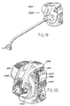
- FIG. 1A of the drawings Illustrated in FIG. 1A of the drawings is a four-stroke internal combustion engine 20.
- the engine 20 drives a conventional shaft typically housed in a shaft tube 22 which in turn drives an implement having a rotary head, cutting filament or blade, rotary impeller, or the like, depending on the type of power tool in use (see, e.g., FIG. 19).
- the shaft arrangement shown in FIG. 1A (and FIG. 19), typically used in conjunction with a hand-held power trimmer, is used for illustrative purposes only and it should be understood that other power tools such as those mentioned previously herein are capable of utilizing the four-stroke engine.
- the engine is preferably used in an orientation where the implement or working tool has an axis which is substantially parallel with a crankshaft axis.
- the engine may also be orientated with the crankshaft being horizontal or vertical.
- the engine is particularly well suited for those applications in which high RPMs, e.g., 3,000 RPMs up to 7,000-8,000 RPMs or more, may be required and in which an output of less than 1 to over 6 horsepower may be supplied.
- the engine is capable of working, at least temporarily, in substantially any operational position of the power tool.
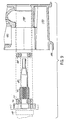
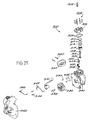
- FIG. 1 of the drawings Illustrated in FIG. 1 of the drawings is an exploded perspective view showing various components of the four-stroke internal combustion engine 20 .
- Shown in FIG. 1 is a side valve or "L" head engine in which the various features are employed.
- Side valve engines are sometimes referred to as “L” head engines because of the positional relationship of an intake valve and an exhaust valve with respect to a combustion chamber.
- the “L” is in reference to the path taken by an air/fuel mixture and the exhaust through respective valves and ports found in the engine body.
- the intake valve port and the exhaust valve port are located in the engine housing, not in the cylinder head which is generally common to overhead valve or overhead cam engines.
- FIG. 1 The components shown in FIG. 1 are identified for the sake of clarity. Shown are an ignition coil screw 24 used to attach an ignition coil (not shown) to the engine 20; shroud screws 27 attach shroud 26 to an engine housing 28; cover screws 30 attach sump cover 32 and sump cover gasket 34 to the engine housing 28 in order to seal one end of the engine housing 28; cylinder head screws 36 attach cylinder head 38 and cylinder head gasket 40 to the engine housing 28 thereby at least partially defining a combustion chamber 39 (FIG. 2); carburetor 42 and muffler 44 are appropriately connected to the engine 20; carburetor 42 cooperates with intake port 41 and air cleaner or filter 43 (FIG.
- an ignition coil screw 24 used to attach an ignition coil (not shown) to the engine 20
- shroud screws 27 attach shroud 26 to an engine housing 28
- cover screws 30 attach sump cover 32 and sump cover gasket 34 to the engine housing 28 in order to seal one end of the engine housing 28
- cylinder head screws 36 attach cylinder head 38 and
- muffler 44 cooperates with exhaust port 45; flywheel 46 which includes an integral fan (not shown) is positioned between the shroud 26 and engine housing 28 with the help of a flywheel key (not shown) in order to cool the engine 20 during operation; piston 48 is received by piston bore 50 within engine housing 28; intake valve 52 and exhaust valve 54 are positioned adjacent piston bore 50 within engine housing 28; intake valve seat 56 and exhaust valve seat 58 are placed within engine housing 28 to cooperate with the respective heads of valves 52 and 54; valve springs 60 are placed in a valve spring chamber and held within the valve spring chamber by valve spring keepers 62; the valve spring chamber is sealed by valve cover 64 and valve cover gasket 66; crankshaft bearing 68, crankshaft bearing 70, worm-helical or spiral gear 74, counterweight 76, crank pin 78 and crankshaft 80 are part of crankshaft assembly 82; counterweight 76 includes an aperture 77; connecting rod 84 includes connecting rod bearings 86 and 88; one end of connecting rod 84 fits over crank pin 78 and
- cam shaft assembly 106 2), and worm-helical or spiral gear 104 are part of cam shaft assembly 106; cam cap 108 and cam cap gasket 110 are attached to engine housing 28 by cam cap screws 111 in order to seal cam shaft assembly 106; tappets 112 are properly positioned within the engine 20 to cooperate with valves 52 and 54; spark plug 114 is positioned in a spark plug hole within cylinder head 38; divider 116 having slots 118, 120 and 122 is disposed within engine housing 28 and at least partially defines a crank chamber 124 and a lubricant or oil reservoir 126; and the piston bore 50 includes an extension 128 which at least partially extends into crank chamber 124.
- FIG. 1 Other components and features not clearly shown in FIG. 1 will be described below.
- FIG. 1 shows the carburetor 42 and the exhaust muffler 44 mounted on opposite sides of the engine housing 28.
- the carburetor 42 may be of any type of carburetor that is tippable such as a standard variable venturi diaphragm carburetor found in small gas engines, but a rotary valve carburetor available from, e.g., Walbro, is particularly well suited.
- the air cleaner or filter 43 (schematically shown in FIG. 2) is mounted in or near an inlet of an intake passage in the carburetor 42.
- a fuel tank (not shown in FIG. 1) is mounted typically to a lower surface of the engine housing 28 and cooperates with the carburetor 42 so that fuel and air can be supplied to the intake port 41 (FIG. 2) in the engine housing.
- the engine housing 28 is typically made of a lightweight aluminum alloy casting having a cylindrical bore or piston bore 50 formed therein.
- the piston bore 50 is configured to partially extend into the crank chamber 124 disposed within the engine housing 28.
- the area or space 136 (FIG. 13) between the extended piston bore 50 and divider 116 accepts volumes of the lubricant or oil during operation and storage to prevent too much lubricant or oil from entering the piston bore 50 or valve chamber 156 (FIG. 2).
- the piston 48 is preferably coated, such as with an iron coating, or chrome plated so as to eliminate the need for a sleeve such as an iron sleeve within the piston bore 50.
- piston bore 50 may include an iron cylinder sleeve.
- the divider preferably includes bottom slot 118 which is located directly below the piston bore 50.
- Optional side slots 120 and 122 of the divider 116 may be located substantially directly across from one another at a predetermined distance from the bottom of the piston bore 50.
- the slots 118, 120 and 122 may be replaced with one or more holes or other apertures. The design considerations to determine the size and location of the slots or holes will be apparent below.
- the slots or holes should be configured for different sized engines.
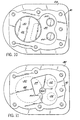
- FIGS. 8 and 8A show another aspect of the divider 116.
- the counterweight 76 is caused to rotate in one direction, usually, a clockwise direction.
- the bottom slot 118 includes opposing sides 130 and 132.
- the second side 132 with respect to the direction of travel of the counterweight 76, has a scraper 134 adjacent thereto.
- the scraper 134 is positioned within .020 to .060 inches of the counterweight 76 when the counterweight 76 is located closest to the scraper 134.
- the scraper 134 limits or meters the amount of lubricant or oil (shown in broken dotted lines) which comes into direct contact with the counterweight 76.
- the scraper 134 helps to limit the amount of lubricant or oil which may be slung into the piston bore 50 during operation and reduces the wind resistance caused by excessive lubricant on counterweight 76. It should be noted that the scraper 134 could be configured in other ways. For example, bottom slot 118 in the divider 116 could be a diagonal slot such that the second side of the diagonal slot acts as the scraper 134 but the scraper is not a raised scraper as shown in FIGS. 8 and 8A. Alternatively, the bottom slot 118 in the divider 116 could be a straight slot without the use of a scraper.
- FIG. 1 shows the oil reservoir 126 disposed within the engine housing 28 defined by the divider 116 and the engine housing 28.
- the oil reservoir 126 is in fluid flow communication with the crank chamber 124, preferably through slots 118, 120 and 122.
- the oil reservoir 126 and the divider 116 are substantially curved or U-shaped.
- the divider 116 is preferably curved to direct lubricant away from the piston bore 50 when the engine is tipped or inverted.
- the communication between the two chambers 124 and 126 allows for the crank chamber 124 to be properly lubricated during use as the lubricant is allowed to flow between the two chambers 124 and 126 during use, and for the lubricant to flow back into the oil reservoir 126 during storage so that an excessive amount of lubricant does not adversely flow into the piston bore 50.
- crankshaft 80 is mounted within the crank chamber 124.
- the crankshaft worm-helical or spiral gear 74 drives the cam shaft assembly 106.
- Worm-helical or spiral gears are commonly known in the art and readily available from any number of gear manufacturers and suppliers.
- the crankshaft 80 and gear 74 may be manufactured in any number of known ways. However, injection molding the gear around a trim metal piece representing the crankshaft would work well.
- the injection mold material may be a thermoplastic material or nylon material known to those skilled in the art.
- Another alternative is to provide a metal crankshaft with an enlarged cylindrical piece of metal on the crank where a worm-helical or spiral gear is intended to be located. The crankshaft then is subjected to a hobbing procedure in which the gear is machined on the crankshaft.
- bearings 68 and 70 are positioned around the crankshaft 80 in order to support the cantilevered crankshaft 80 when it is placed within the crank chamber 124.
- the bearings 68 and 70 are placed on opposite sides of the worm-helical or spiral gear 74 and on the same side of the piston bore 50.
- the inner bearing 68 is smaller in diameter than the outer bearing 70.
- the bearings 68 and 70 are dimensioned in this manner such that the bearing pockets found in the crank chamber 124 are machined from one side of the engine housing 28 using only one tool. As can be appreciated by those skilled in the art, machining bearing pockets from one direction reduces equipment, time and expense usually associated with having to machine bearing pockets from different directions.
- counterweight 76 is mounted on one.end of the crankshaft 80.
- FIGS. 7, 7A and 7B show in greater detail the shape and contours of the counterweight 76.
- the counterweight 76 includes wing-tipped aerodynamic sides 138 and 140. Each wing-tipped side includes a back 142 that is positioned adjacent the main bearing 70 and a front 144 opposite the back 142.
- the wing-tipped sides 138 and 140 have contoured surfaces that extend from the back 140 to the front 142 of the counterweight 76.
- the aerodynamic shape of the counterweight 76 assists in reducing air resistance on the counterweight 76, generating the proper turbulence of air and lubricant within the internal cavity of the engine 20 and directing the lubricant within the internal cavity of the engine 20.
- FIGS. 7 and 9 schematically show a tool 146 which is used to position the outer bearing 70, counterweight 76 and the crankshaft 80 within the crank chamber 124.
- Bearing 68 is press fitted into the crank chamber 124 and is adapted to receive one end of the crankshaft 80.
- the bearing 70 is press fitted onto the crankshaft 80.
- the counterweight 76 is then fixed to the crankshaft 80.
- FIG. 7A illustrates a step 141 which provides a clearance of approximately .050 of an inch between the counterweight 76 and bearing 70. As shown in FIG.
- FIG. 6 schematically illustrates how the connecting rod 84 is attached to the crankshaft 80 and piston 48.
- a custom shoulder bolt (not shown) may be utilized to affix the connecting rod 84 to the crank pin 78.
- the entire crankshaft assembly 82 (FIG. 1) is mounted within the crank chamber 124 (FIG. 3).
- the piston 48 is slid into the piston bore 50 from the top of the engine housing 28.
- the aperture 92 in the piston 48 is lined up with the access aperture 93 in the engine housing 28.
- the connecting rod 84 is attached to the crankshaft assembly 82 by virtue of crank pin 78 and positioned within a cut out portion 148 of the piston 48.
- the wrist pin 90 is inserted through the access hole 93 of the engine housing 28 into the access hole 92 of the piston 48 and through the bearing 86 of the connecting rod 84. Since the aperture 92 of the piston 48 is not drilled all the way through the piston 48, one end of the wrist pin 90 abuts an inner portion 150 of the piston 48.
- the wrist pin 90 can be held in place within the piston 48 by a star washer 151 inserted in the open end of the aperture 92 (see also FIG. 5).
- the wrist pin 90 and the crank pin 78 are hollow so as to reduce the overall weight of the reciprocating mass which in turn means a smaller counterweight with less weight is needed to balance the forces generated by the reciprocating mass. Reducing the overall weight of the reciprocating components improves vibration and makes the engine lighter for ease of operation.
- the cam shaft 98, the eccentric style cam lobes 100 and 102 and the cam gear 104 are shown as separate parts in FIG. 2. It should be noted that these parts can be injected molded as a single component using, for example, a thermoplastic or nylon material. Alternatively, certain components may be injected molded around a piece of trim metal to create the final assembly in similar manner to that contemplated for the crankshaft 80 and worm-helical or spiral gear 74.
- FIG. 2 illustrates that the cam shaft 98 includes a passageway 152.
- FIGS. 2, 3 and 4 show that a portion of the cam shaft assembly 106 (FIG. 1) adjacent the worm-helical or spiral gear 104 includes at least one radial aperture 154 exposed to the passageway 152 and crank chamber 124.
- the passageway 152 and aperture 154 may be drilled into the proper portions of the cam shaft assembly 106 or molded therein.
- the passageway 152 and the aperture 154 and cam shaft assembly 106 cooperate to provide a breather arrangement for the internal combustion engine which will be fully outlined below.
- the radial aperture 154 may be found in a radial disc (not shown) attached to the cam shaft assembly 106 in close proximity to the gear 104 so as to be in communication with the passageway 152 and crank chamber 124.
- the cam shaft 98 is located normal to the crankshaft 80.
- the cam shaft and the crankshaft are parallel to one another, not normal as shown.
- a parallel arrangement leads to a wider engine whereas the normal arrangement leads to a longer engine design with the crankshaft axis being substantially parallel to the longitudinal axis of the tool.
- a longer unit is particularly desirable for those hand-held applications such as power trimmers which require better balance for ease of operation.
- a wider engine may tend to cause the unit to want to rotate in the operator's hands during use.
- FIG. 2 shows that cam shaft 98 sits in bushings 94 and 96 which rest in respective pockets within the crank chamber 124 in engine housing 28.
- the worm-helical or spiral gears 74 and 104 are preferably designed such that when cam shaft 98 is placed generally normal to crankshaft 80, the gears 74 and 104 mesh so that the rotational relationship between the crankshaft 80 to cam shaft 98 is 2 to 1.
- the tappets 112 and the intake valve 52 and the exhaust valve 54 cooperate with cam shaft 98 (FIG. 2).
- Intake valve 52 and exhaust valve 54 are positioned within engine housing 28 adjacent to piston 48 and piston bore 50.
- the valves 52 and 54 are positioned such that the valve heads are closer to the centerline of the bore 50 as compared to the lower portions of the valves (FIG. 3).
- the valves 52 and 54 are set at an angle of approximately between zero and eight degrees from a line parallel with the centerline of the bore.
- the intake valve seat 56 and the exhaust valve seat 58 are placed within engine housing 28 and cooperate with the heads of the respective valves 52 and 54 to alternately create a seal or an opening into the combustion chamber 39 with respect to the ports 41 and 45.
- valve spring keepers 62 and valve compression springs 60 are positioned within the valve chamber 156 (FIG. 2).
- Each tappet 112 includes a respective head 158 which is in operational contact with respective cam lobes 100 and 102.
- cam shaft 98 rotates by virtue of drive gear 74, cam lobes 100 and 102 properly engage tappets 112 such that valves 52 and 54 move up and down as is commonly understood by those skilled in the art.
- the crank chamber 124 is in communication with the valve chamber 156 via access passageway or aperture 160. Additionally, the valve chamber 156 is in communication with the piston bore 50 via access passageway or aperture 162.
- the passageways 160 and 162 allow valve chamber 156 and the components therein to receive lubricant during operation of the engine 20 in substantially any attitude. Additionally, during storage, with the aid of divider 116, the extended piston bore 50, and the slots 118, 120 and 122, a significant amount of lubricant will not remain or flow into the valve chamber 156.
- cylinder head gasket 40 is positioned between the cylinder head 38 and the engine housing 28 so as to provide a proper seal between the two.
- Spark plug 114 projects into the enclosed combustion chamber 39. Spark plug 114 fires in combination with the ignition coil and magneto (not shown) to provide the necessary charge or high voltage signal to ignite the air/fuel mixture in the combustion chamber 39 when the engine 20 is in operational mode.
- FIGS. 10 and 11 schematically show, at least in part, the combustion chamber 39 with respect to the intake valve 52, exhaust valve 54 and piston bore 50.
- the combustion chamber 39 only partially extends over the piston bore 50.
- the orientation of the combustion chamber 39 and shape of the combustion chamber 39 enhances swirl in the mixing chamber 39 so as to provide a better air/fuel mixture to enhance ignition of the mixture.
- the spark plug 114 is positioned closer to the exhaust valve 54 than it is to the intake valve 52.
- the electrode 164 is properly oriented to provide a firing spark. Placing the spark plug 114 nearer the exhaust valve 54 allows the hotter air/fuel mixture to be burned sooner by the spark ignited flame front. This will reduce the self-ignition tendency of the hotter air/fuel mixture at the exhaust side of the combustion chamber 39. If the spark plug 114 is positioned closer to the intake valve 52, there is a risk of having two combustions, resulting in a loss of power.
- the intake port 41 and the exhaust port 45 are located 180 degrees apart from each other.
- the position of the valves 52 and 54 is a result of the substantially normal arrangement of the cam shaft 98 and crankshaft 80 and allows the ports 41 and 45 to be positioned on opposite sides of the engine housing 28.
- This provides an additional feature of operator safety.
- the exhaust port 45 and muffler 44 (FIG. 1) are positioned farther away from the operator during use.
- Another advantage of placing the ports 41 and 45 as far apart as possible is to reduce heat migration from the exhaust port 45 to the intake port 41 which, if did occur, could result in hot restart vapor lock issues, or difficulty in calibrating the air/fuel ratio.
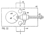
- FIG. 12 shows a schematic representation of the path traveled by the air/fuel mixture and exhaust through the engine 20.
- the air/fuel mixture enters the intake port 41, travels past the intake valve 52, and into the combustion chamber 39.
- the engine 20 combusts the air/fuel mixture in order to generate power, and the remaining exhaust travels past the exhaust valve 54 and out the exhaust port 45.
- the arrangement of the cam shaft 98 and the crankshaft 80 is also shown to illustrate how such an arrangement contributes to the overall scheme associated with the air/fuel and exhaust paths through the engine 20.
- the four-stroke engine is capable of use in substantially any position.
- a problem with prior conventional four-stroke engines is that if the engine is substantially tilted, the lubricant will run into undesirable locations, such as the carburetor, thereby causing the engine to malfunction or cease working altogether.
- the four-stroke engine is designed to solve this problem and other problems typically associated with conventional four-stroke engines.
- the oil or lubricant reservoir 126, the crank chamber 124, the piston bore 50, and the valve chamber 156 include strategically placed slots, passageways, or apertures so as to enable various working components within the engine to be lubricated at virtually all times during operation.
- the counterweight 76 has been designed such that only a proper amount of lubricant comes into contact with the counterweight 76.
- the design of the counterweight 76 also allows the counterweight to meter the amount of lubricant that finds its way to the main bearing 70 so as not to flood that part of the crank chamber 124 encapsulating the gears 74 and 104. This also will help prevent too much lubricant from entering the valve chamber 156 through passageway 160 and 162.
- the piston bore 50 and divider 116 have been designed to ensure that the lubricant has a place to go regardless of whether the engine is operating or being stored, so as not to foul the internal components of the engine.
- lubricant or oil is stored within the oil or lubricant reservoir 126.
- the level of the lubricant is preferably below the bottom slot 118 in the divider 116.
- the reciprocating movement of the piston 48 creates pressure pulses within the internal cavity of the engine 20.
- the lubricant moves in response to the movement of the piston 48.
- the counterweight 76 agitates the lubricant or oil and blow-by gas within the inside cavity of the engine 20.
- the lubricant is forced through the main bearing 70 to lubricate the bearings 70 and 68, the worm-helical or spiral gears 74 and 104, the crankshaft 80, the cam shaft 98 and the bushings 94 and 96 due to increased pressure in the engine cavity.
- the action of the cam gear 104 will cause some lubricant to enter aperture 160 and migrate to the valve chamber 156.
- any oil found in piston bore 50 could be pushed into aperture 162 to also lubricate the valve chamber 156.
- the lubricant On the upward strokes, i.e., the compression and exhaust strokes, the lubricant will be drawn back over the just mentioned areas to further lubricate the components due to a partial vacuum in the engine cavity.
- the reciprocating movement of the piston 48 moves the lubricant back and forth within the internal cavity of the engine 20.
- the invention does not require a control valve to control movement of the lubricant.
- the counterweight 76 preferably does not dip directly into the lubricant, although direct dipping could be used. The more direct contact made with the lubrication, the more energy that is lost from the engine 20. The least amount of lubricant resistance is desired. As mentioned, the counterweight 76 is designed to throw the lubricant away from the main bearing 70 and towards the sump cover 32. The design of the counterweight 76 also limits the amount of lubricant slung into the piston bore 50. In this way, only a limited amount of oil will find its way to the valve chamber 156.
- the counterweight 76 is designed to reduce the amount of drag that the counterweight 76 has when it is rotating through and churning up the lubricant. In addition, the counterweight 76 design reduces windage which creates a more efficient engine. It should be noted that although the counterweight 76 is shown and described as the device which agitates the lubricant and blow-by gas within the intemal cavity, a separate agitator may be provided to accomplish the same results. Such an agitator may be a splasher or mixer attached to the rotating crankshaft or connecting rod, or caused to rotate in any number of other ways.
- the extended piston bore 50, the divider 116, the slots 118, 120 and 122, and the passageways 160 and 162 ensure that the engine will continue to function properly, for at least a limited amount of time, or be capable of storage in this position without fouling the engine.
- the changing pressure pulses, the blow-by gas and the agitator 76 will cause the lubricant to be mixed and moved inside the cavity of the engine 20. Although some oil will be flung into the piston bore 50, not a significant amount will go there.
- the access passageway 162 is located such that the oil ring 166 in the piston 48 does not travel over or past the passageway 162 as the piston 48 reciprocates within the piston bore 50 (FIG.5). Otherwise, it would be possible for lubricant found within the valve chamber 156 to find its way into the combustion chamber 39, thereby burning off the lubricant and creating excess emissions.
- the crank chamber 124 includes the area or space 136 between the extended piston bore 50 and divider 116 for receiving oil or lubricant when the engine is tilted or inverted as representatively shown in FIG. 13.
- the slots 118, 120 and 122 will allow most of the oil to remain in the oil reservoir 126, and the area 136 between the divider 116 and the piston bore 50 will hold most of the remaining lubricant. Any oil left in the valve spring chamber 156 during use is thought to be negligible and will not significantly affect the operation of the motor. Importantly, because of the positioning of the slots 120 and 122 above the oil in the inverted position, the valve chamber 156 will not be able to receive any significant amount of oil.
- the oil reservoir 126 should be in communication with the crank chamber 124 so as to allow for proper lubrication of the engine 20 in substantially any operational position.
- the various described slots, passageways, holes and apertures perform at least two functions. First, if the engine 20 is operating in a sideways condition, the slot 120 or 122 in the divider wall 116 facing down towards the ground allows oil to travel into the crank chamber 124 with the pressure pulsations in a manner similar to when the engine is in an upright state during which lubricant moves through the bottom slot 118.
- the side slots 120 and 122 allow oil to migrate from the crank chamber 124 to the oil reservoir 126 so as to prevent the piston bore 50 and valve chamber 126 from undesirably receiving a significant amount of lubricant.
- the cam shaft 98 is provided with a hollow passageway 152 and properly positioned radial passages 154.
- one end of the cam shaft cover 108 includes a nipple 168 which is attached to a flexible hose 170 (schematically shown).
- a flexible hose 170 (schematically shown).
- the blow-by gas As the pressure pulse forces the lubricant/blow-by gas mixture through the main bearing 70, the blow-by gas is driven into the radial holes 154 and passageway 152 while the oil is prevented from passing through the holes 154 as a result of the centrifugal action of the operating cam shaft 98.
- the blow-by gas travels through the cam cover 108 and nipple 168 affixed to cam cover 108, through the flexible hose 170 and back into the intake of the carburetor 42.
- a check valve may be positioned between the end of the cam shaft 98 and the air intake system to maintain the negative pressure created within the engine.
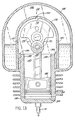
- FIG. 14 shows a cross-sectional view of the four-stroke engine with a starter mechanism 172 attached to the sump cover plate 32 with screws 30.
- a crankshaft adapter 174 is connected to crank pin 78.
- a clutch bearing 176 is press fitted around the crankshaft adapter 174.
- a starter shaft 178 is positioned around the clutch bearing 176 and is keyed or molded to the starter 180.
- An oil seal or O-ring 181 is placed around the starter shaft 178 to provide a seal between the starter mechanism 172 and the sump cover 32.
- a thrust washer or bearing 182 is placed on each side of the starter 180.
- Starter 180 is preferably a rewind starter having a pull cord 184.
- Locating the starter mechanism 172 or the sump cover 32 on the back of the engine 20 enables the operator to have easy access to the pull cord. Further, integrally connecting the starter to the piston 48 through connecting rod 84 and the crankshaft 80 through the crank pin 78 reduces the rope pull force needed to start the engine 20. Alternatively, other starter assemblies may be utilized.
- FIGS. 15-18 depict a layout for the dies used to manufacture an engine housing .
- the engine housing is designed to permit two engine housings to be produced using one die tool and one die casting machine.
- the engine housing is designed to include walls which allow for the needed draft angles given different orientations for each engine housing within the die tool. The draft angles enable the engine housing to readily separate from the die.
- the engine housing is designed to permit slide tooling access (i.e., the piston and cam shaft bores) when two engine housings are fabricated from one tool.
- the dies 188 and 190 are formed so that the centerlines of the engine cylinder bores (which are parallel to direction C) are parallel to each other. Boxes 194 and 196 represent the edges of the tool.
- the inserts used to form the dies are inserted only along a few directions, i.e., in directions A, B and C.
- This die configuration reduces the overall space required to make the engine housings, while still enabling two engine housings to be made at the same time.
- the two die halves 188 and 190 are parted along parting line 192.
- the back wall of the engine housing is not shown and is separately formed and then fastened to the engine housing with bolts or other suitable fasteners. It is, however, possible that the back wall could be formed integral with the engine housing according to the principles set forth above.
- the parting line 192 could be moved to another location. The draft angles of the engine housing outer walls would change accordingly so as to accommodate the new location of the parting line.
- FIGS. 39-40 depict another layout for the die 529 used to manufacture an engine housing.
- the die 529 is laid out in such a manner that the centerlines of the piston bores are parallel but in opposite directions. Further, both cavities are oriented such that the stationary bodies of material compose the internal features of the oil reservoir, the barrier wall and the inner crank chamber.
- the engine housing is designed to include walls of which are needed for draft angles parting line jumps, and slide shut-offs for the given orientation within the die layout. By orienting the die in such a prescribed manner, the inserts for the die pieces are inserted only along a few directions, i.e., in directions D, E, F and G. This embodiment of the die layout also serves to minimize the overall space necessary to manufacture the two-engine housings out of a single die.
- the datum targets or reference features for both cavities are created by the same piece of stationary material.
- these references By having these references on the same piece of stationary material, there is less variance to accommodate between the casting in the machining of the finished engine housing. This further translates into less variance in the finished-machined engine housing even though the casting is being derived from two separate cavities.
- this embodiment also integrally creates the flywheel back-plate into the engine housing casting. It is further desirable to gate 531 the casting into the deck of the cylinder and route the gates parallel to directions F and G into the cavities.
- FIGS. 19-40 illustrate another four-stroke internal combustion engine in which the features previously described may be employed and which incorporates additional inventive features not yet previously described. It should be noted that the features specifically described in relation to FIGS. 19-40 may be incorporated into the engine described in FIGS. 1-18, or other engines.
- FIG. 19 illustrates a four-stroke internal combustion engine 300.
- the engine 300 is shown as used in a power trimmer but may be used in other devices as described for the engine of FIG. 1.
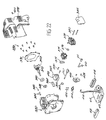
- FIGS. 21 and 22 are identified for the sake of clarity. Many of the components are assembled in the same or similar manner as described in reference to FIG. 1 or as generally understood by those skilled in the art Accordingly, the manner of assembly is not described in great detail below. Shown in FIG.
- spark plug 302 are spark plug 302; cylinder head screws 304; cylinder 306; cylinder head gasket 308; compression rings 310 and 312 and oil ring 313 which are appropriately positioned in annular slots located in piston 314; connecting rod 316 and connecting rod bearings, preferably needle roller bearings, 318 and 320; exhaust valve 322, intake valve 324, valve springs 326 and valve spring keepers 328; engine housing 330; valve cover 332 and associated screws 334; flywheel 336, crankshaft adapter 338, ignition coil 340, wiring assemblies 342 and 346, and screws 344 all of which are part of a starter assembly; muffler mounting bolts 350; muffler 352; and blower housing 348 which is part of an overall shroud further described below.
- sealing O-ring 366 and oil gauge 367 Shown in FIG. 22 are sealing O-ring 366 and oil gauge 367; intake gasket 368, intake isolator 369 and screws 370; carburetor gasket 372, carburetor 374 and O-ring 376; air filter assembly 378, screws 380 and air filter cover 382; wrist pin 384 and star washer wrist pin retainer 386; oil sealing ring 388, roller bearing 390, crankshaft 392 and counterweight 393; sump cover 394 and screws 396; muffler housing 398 which is part of an overall shroud further described below and mounting screws 400; tappets 402, cam shaft 404, cam shaft cover 406; screws 408 and breather tube 410; check valve 411; fuel tank 412. having fuel line 414, opposing shoulders 416; and filter material 418 which is placed around shoulders 416 as further described below.
- FIGS. 21 and 22 Other components and features not clearly shown in FIGS. 21 and 22 will be described below. Moreover, the significance of any of the components shown in FIGS. 21 and 22 or their interaction, will be described below.
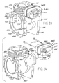
- FIG. 23 more clearly shows the engine housing 330 with the muffler 352 attached thereto by mounting bolts 350.
- the engine housing 330 includes a crankcase 420 and a cylinder 422.
- the cylinder head 306 (FIG. 21), which at least partially defines a combustion chamber, is disposed adjacent to the cylinder 422.
- a crank chamber 426 is disposed within the crankcase 420.
- An oil reservoir 428 is also disposed within the crankcase 420 and is in fluid flow communication with the crank chamber 426, preferably, through slot 430 and opposing holes 432 (only one being shown) disposed in a divider 433.
- the divider 433 is disposed within the crankcase 420 and at least partially divides the crank chamber 426 and the oil reservoir 428.
- a plurality of holes 434 are provided in the engine housing 330 so that the sump cover 394 and sump cover gasket can be attached thereto.
- the engine housing 330 also includes an oversized wrist pin boss 436.
- the wrist pin boss 436 may be integrally formed with the divider 433. The function of the wrist pin boss 436 will be further described below.
- the engine housing 330 also includes a flywheel back plate 438 with at least one mounting boss 440, the function of which will be described below.
- FIG. 24 is an exploded perspective view of FIG. 23 showing how the muffler 352 is connected to the engine housing 330.
- the cylinder 422 includes an exhaust port 442 and an intake port 444 (FIG. 25).
- the intake port 444 and exhaust port 442 are elliptical in shape thereby enabling the overall height of the engine housing 330 to be reduced. This will naturally reduce the overall weight of the engine housing, which is an especially important factor for hand-held power tools.
- the walls of the ports 442 and 444 are provided with sufficient material so as to be able to support the weight of the engine housing 330 and cylinder head 306 disposed thereabove.
- the muffler 352 includes a boss 446 which is preferably elliptical.
- the boss 446 extends into the exhaust port 442.
- Mounting bolts 350 extend through holes 448 in the muffler 352 and into holes 450 formed in the cylinder 422.
- the holes 448 are spaced apart and positioned on opposite sides of the exhaust port 442 to maximize the stability of the muffler 352 with respect to its connection to the cylinder 422.
- FIGS. 26 and 27 are enlarged partial cross-sectional views taken along line 26-26 of FIG. 23 showing preferred alternative mounting connections between the muffler 352 and cylinder 422.
- FIG. 26 shows the engine housing 330 having an angled, step sealing surface 452 located in the exhaust port 442 of cylinder 422.
- the end 454 of boss 446 can mate against the exhaust port scaling surface 452 to substantially prevent exhaust from undesirably escaping into the environment.
- a sealing gasket 456 is positioned between the end 454 of the boss 446 and the sealing surface 452 to even better prevent the exhaust from escaping.
- FIG. 27 shows the outside liner of the boss 446 of the muffler 352 surrounded by the surface 458 of the exhaust port 442, thereby defining a clearance space 460 therebetween.
- surface 458 is shown as an angled surface, it may take on other configurations so long as clearance space is provided between the muffler 352 and the exhaust port 442.
- a gasket 462 is positioned between the muffler 352 and cylinder 422 or engine housing 330 to seal the clearance space 460, thereby preventing exhaust from escaping into the atmosphere.
- the gasket 462 is an enlarged gasket which also serves as a heat shield between the engine housing 330 and the muffler 352.
- the muffler 352 (FIG. 24) preferably includes a pair of outer shells 464 and 466 having respective mounting bolt holes 448 for the mounting bolts 350.
- An inner shell or baffle plate (not shown) is preferably located between the outer shells 464 and 466.
- the inner shell also is adapted to allow the mounting bolts 350 to pass therethrough.
- the baffle plate is designed to reduce noise.
- Outer shell 464 includes a shoulder 470 which extends around an edge of the outer shell 464.
- Outer shell 466 includes a flange (not shown) which extends around an edge of the outer shell 466. Upon assembly, the shoulder 470 receives the flange such that if exhaust does leak out of muffler 352, the exhaust will leak away from the engine.
- a deflector may be placed over the exhaust holes 372 (FIG. 23) of the muffler 352 to protect the operator from receiving a direct blast of exhaust.
- the oversized wrist pin boss 436 (FIG. 23) is provided.
- the wrist pin boss 436 can be machined at its upper end 474 to provide an access hole (not shown) in the crankcase 420 for a first piston throw, and the wrist pin boss 436 can be machined at its lower end 476 to provide an access hole (not shown) in the crankcase 420 for a second piston throw.
- the wrist pin 384 (FIG.
- FIG. 22 is inserted through the crankcase access hole and into the piston access hole to connect the piston 314 (FIG. 21) to the connecting rod 316 (FIG. 21).
- FIG. 31 shows a completed assembly on such engine.
- FIG. 32 shows the piston 314 in its bottom most dead center position so that the wrist pin 384 can be appropriately positioned within the engine.
- FIG. 28 is an enlarged view of the engine housing 330 of FIG. 24 without the muffler 352.
- the divider 433 defines a path 478 which extends substantially about the divider 433 and over the wrist pin boss 436.
- the path 478 allows lubricant found in the oil reservoir 428 to flow around a substantial portion of the divider 433 to further enhance the lubricating and storage features .
- the path 478 allows the amount of lubricant found on both sides of the divider 433 to equalize when the engine 300 is turned upside down. This further inhibits a substantial amount of the lubricant from migrating into the crank chamber 426.
- FIG. 25 is a perspective view of the engine housing 330 of FIG. 23 only from a different perspective.
- the opposite side of the flywheel back plate 438 also includes at least one mounting boss 480.
- an assembly fixture (not shown) is adapted to hold the engine 300.
- Each mounting boss 440 and 480 receives a separate pin (not shown) of the assembly fixture to secure the engine housing 330 to the assembly fixture.
- a shroud 482 (FIG.
- the shroud comprises the blower housing 348 (see also FIG. 21) and muffler housing 398 (see also FIG. 22).
- Shroud 482 includes at least one slot 484. Each slot 484 is designed to surround a respective pin of the assembly fixture extending out of the mounting bosses 440 and 480 when the shroud 482 is positioned around the engine housing 330.
- the shroud 482 can be attached to the engine housing 330 by threading screws 486 (FIG. 20) into respective holes such as hole 488 (FIG. 25) of the engine housing 330.
- the entire engine 300 can be substantially assembled while remaining attached to a single assembly fixture.
- the muffler housing 398 preferably includes a plurality of raised portions 490 (FIG. 31).
- the engine 300 may be placed on the ground to rest on the raised portions 490.
- the blower housing 492' of FIG. 31 is slightly different from the blower housing shown in FIG. 20. The purpose of this is to show that various suitable configurations of the shroud 482 are possible.
- the shroud 482 is provided with an opening 494 which surrounds the intake port 444 (FIG. 25).
- An intake isolator 369 (FIG. 22) having an air/fuel passageway 496 (FIGS. 29 and 30) extending therethrough is provided.
- the intake isolator 369 is mounted to the engine housing 330 so that the air/fuel passageway 496 is aligned with the intake port 444.
- the intake isolator 496 is positioned within the opening 494 of the shroud 482 to substantially ensure that cooling air passing between the engine housing 330 and the shroud 482 cannot escape through the opening 494 in the shroud 482.
- the intake isolator 369 includes an integrally formed back wall 498 and a side wall 500 (FIG. 22) to accomplish this feature.
- crankcase 420, the cylinder 422 and the back plate 438 are cast as a single component.
- the engine. housing 330 further includes at least one fin 502 integrally formed thereto (FIG. 28). The fin 502 extends from the back plate 438 and beneath the crankcase 420 for stability and cooling purposes.
- the shroud 482 may be of many different designs consistent with the principles of the present invention, the shroud 482 is designed to hold the fuel tank 412. As best shown in FIG. 31, the shroud 482 is provided with a pair of opposed channels 504 (only one is shown). The outwardly extending shoulders 416 (see also FIG. 22) are received by the respective channels 504 so that the fuel tank 412 is held by the shroud 482.
- the filler material 418 (see also FIG. 22), preferably a polyethylene, high-density, closed cell, high-temperature and gasoline-resistant foam material, is positioned between each channel 504 and the respective shoulder 416 to provide a tight fit between the shroud 482 and the fuel tank 412.
- the fuel line 414 (FIG.
- the 22 includes a fuel Biter 506 attached to the end of the fuel line 414 disposed within the fuel tank 412. It should be noted that the extra line shown in FIG. 22 is a purge line.
- the fuel filter 506 acts as a weight such that during operation of the engine, if the engine is tipped, the weighted fuel line 414 swings to the bottom of the fuel tank 412 to ensure that fuel is picked up by the fuel line 414.
- the blower housing 348 is provided with a hub 508 having an inwardly facing extension 510.
- the hub 508 is adapted to fit over the crankshaft 392 (FIG. 22) or crankshaft adapter 338 (FIG. 21).
- the starter assembly 507 which includes the pulley 516, rope 518 and spring 520 is positioned onto the hub 508.
- a star washer 514 is placed over the hub extension 510 so as to dig into the extension material. The star washer 514 holds the starter assembly 507 in place with respect to the blower housing 348. This arrangement eliminates the need for separate mounting bosses and fasteners typically needed to hold the starter assembly in place. Such mounting bosses and fasteners generally block the cooling air flow by a fan.
- FIGS. 34-38 show various views of the pulley 516.
- the spring 520 (FIG. 33) is positioned on one side 522 of the pulley 516 having an appropriately shaped annular recess 524.
- the opposite side 526 of the pulley 516 includes a plurality of spokes 528 for engagement with a flywheel such as flywheel 336 shown in FIG. 21.
- the rope 518 includes a knot 530 on one end thereof which is held in a chamber 532 formed in a hub 534 of the pulley 516 beneath the pulley rope portion 536.
- the rope 518 extends through a hole 538 in the pulley rope portion 536 and is wrapped around the pulley 516.
- the other end of the rope 518 is attached to a starter handle 540 (FIG. 20).
Description
Claims (13)
- A four-stroke internal combustion engine (20), comprising:an engine housing (28,330) including a crankcase and a cylinder (50,422);a cylinder head (38, 306) which at least partially defines a combustion-chamber, said cylinder head (38, 306) disposed adjacent to said cylinder (50, 422);an intake valve (52, 324) and an exhaust valve (54,322) disposed within the engine housing (28, 330);a crank chamber (124, 426) disposed within said crankcase;a crankshaft (80, 392) supported for rotation within said crank chamber (124, 426);a piston (48, 314) operably interconnected with said crankshaft (80,392) for reciprocation within said cylinder (50, 422) in response to rotation of said crankshaft (80, 392);an oil reservoir (126, 428) disposed within said crankcase and in fluid flow communication with said crank chamber (124, 392);a divider (116, 433) disposed within said crankcase in order to separate said crank chamber (124, 392) from said oil reservoir (126, 428) and defining a first aperture (118) at a location opposite the cylinder (50, 422) to permit fluid flow between the oil reservoir (126, 428) and the crank chamber (124, 426), the divider (116, 433) being curved to direct lubricant in the reservoir away from the cylinder (50, 422) when the engine is tipped or inverted and defining second and third apertures (120, 122) on opposite sides of the crankshaft (80, 392) to permit drainage of lubricant out of the crank chamber (124, 426) into the oil reservoir (126, 428) when the engine is tipped or inverted;a cylinder side wall (128) extending into the crank chamber (124, 426) to define a lubricant receiving space (136) between the divider (116, 433) and the cylinder side wall (128) in order to keep excessive lubricant out of the cylinder (50, 422) when the engine is tipped or inverted; andan agitator (76) located at least partially within said crank chamber (124, 426), said agitator (76) moving lubricant within said engine housing (28, 330) during operation of said engine.
- An engine according to claim 1, wherein said engine housing (28, 330) further includes a valve chamber (156) in which said intake valve (52, 324) and said exhaust valve (54, 322) are disposed, said valve chamber (156) being in fluid flow communication with said crank chamber (124, 426).
- An engine according to claim 1, further comprising a cam shaft (98, 404) rotatably driven by said crankshaft (80, 392) and oriented substantially normal to said crankshaft (80, 392).
- An engine according to daim 3, further comprising first and second valve tappets associated with a respective valve (52, 54; 322, 324) and operatively engaging said cam shaft (98, 404), the valves (52, 54; 322, 324) being disposed substantial normal to said crankshaft (80, 392).
- An engine according to claim 3, wherein said cam shaft (98, 404) has an axial passageway (152) and a radial aperture (154) communicating between said crank chamber (124, 426) and said passageway (152), the engine further comprising a breather tube (410) having one end communicating with said passageway (152) of said cam shaft (98, 404) and another end communicating with an air intake system (378) of said engine.
- An engine according to claim 1, wherein said crankshaft (80, 392) is cantilevered, said crankcase includes an access hole (93), and said piston (48, 314) includes an aperture (92), said access hole and aperture being alignable during assembly of said engine; and wherein said engine further comprises:a connecting rod (84, 316) having one end pivotally attached to said crankshaft (80, 392) and the other end pivotally connected to said piston (48, 314); anda wrist pin (90, 384) inserted through said access hole (93) into said aperture in said piston to pivotally connect said connecting rod to said piston (48, 314).
- An engine according to daim 1, wherein said crank chamber includes at least two bearing pockets, one pocket having a larger diameter than the other and both pockets being disposed on the same side of said cylinder side wall (128).
- An engine according to claim 1, further comprising a shroud (26, 482) partially surrounding said engine housing (28, 330) and including a pair of opposed channels (504), and a fuel tank (412) having opposed outwardly-extending shoulders such that said shoulders of said fuel tank (412) are received by said respective channels (504) of said shroud.
- An engine according to claim 1, wherein said engine housing further includes a back plate (438) which is adjacent to a flywheel (336), and wherein said crank case (420), cylinder (422), and back plate (438) are cast as a single component,
- An engine according to claim 1, wherein said cylinder (422) includes elliptical intake and exhaust ports (444, 442) on opposite sides of said engine housing, and intake and exhaust valves in communication with said intake and exhaust ports (444, 442), respectively.
- An engine according to claim 1, wherein the divider (116, 433) is substantially U-shaped.
- An engine according to claim 1, wherein one side of the divider (116, 433) is exposed to the oil reservoir (126, 428) and an opposite side of the divider (116,433) is exposed to the crank chamber (124, 426).
- An engine according to claim 1, wherein said cylinder side wall (128) extends into said crank chamber (124, 426) generally parallel to the longitudinal axis of the cylinder (50, 422).
Priority Applications (8)
| Application Number | Priority Date | Filing Date | Title |
|---|---|---|---|
| EP02020880A EP1267053A1 (en) | 1999-01-25 | 2000-01-13 | Four-stroke internal combustion engine |
| EP04022245A EP1486652B1 (en) | 1999-01-25 | 2000-01-13 | Four-stroke internal combustion engine |
| EP02020879A EP1267052B1 (en) | 1999-01-25 | 2000-01-13 | Four-stroke internal combustion engine |
| EP02020881A EP1267054B1 (en) | 1999-01-25 | 2000-01-13 | Four-stroke internal combustion engine |
| DK00904332T DK1147298T3 (en) | 1999-01-25 | 2000-01-13 | Four-stroke internal combustion engine |
| DK02021231T DK1267056T3 (en) | 1999-01-25 | 2000-01-13 | Four-stroke internal combustion engine |
| EP02021230A EP1267055A1 (en) | 1999-01-25 | 2000-01-13 | Four-stroke internal combustion engine |
| EP02021231A EP1267056B1 (en) | 1999-01-25 | 2000-01-13 | Four-stroke internal combustion engine |
Applications Claiming Priority (3)
| Application Number | Priority Date | Filing Date | Title |
|---|---|---|---|
| US11721599P | 1999-01-25 | 1999-01-25 | |
| US117215P | 1999-01-25 | ||
| PCT/US2000/000841 WO2000043655A1 (en) | 1999-01-25 | 2000-01-13 | Four-stroke internal combustion engine |
Related Child Applications (6)
| Application Number | Title | Priority Date | Filing Date |
|---|---|---|---|
| EP02020881A Division EP1267054B1 (en) | 1999-01-25 | 2000-01-13 | Four-stroke internal combustion engine |
| EP02020879A Division EP1267052B1 (en) | 1999-01-25 | 2000-01-13 | Four-stroke internal combustion engine |
| EP04022245A Division EP1486652B1 (en) | 1999-01-25 | 2000-01-13 | Four-stroke internal combustion engine |
| EP02020880A Division EP1267053A1 (en) | 1999-01-25 | 2000-01-13 | Four-stroke internal combustion engine |
| EP02021231A Division EP1267056B1 (en) | 1999-01-25 | 2000-01-13 | Four-stroke internal combustion engine |
| EP02021230A Division EP1267055A1 (en) | 1999-01-25 | 2000-01-13 | Four-stroke internal combustion engine |
Publications (2)
| Publication Number | Publication Date |
|---|---|
| EP1147298A1 EP1147298A1 (en) | 2001-10-24 |
| EP1147298B1 true EP1147298B1 (en) | 2005-03-23 |
Family
ID=22371571
Family Applications (1)
| Application Number | Title | Priority Date | Filing Date |
|---|---|---|---|
| EP00904332A Expired - Lifetime EP1147298B1 (en) | 1999-01-25 | 2000-01-13 | Four-stroke internal combustion engine |
Country Status (8)
| Country | Link |
|---|---|
| EP (1) | EP1147298B1 (en) |
| JP (5) | JP2002535547A (en) |
| CN (7) | CN100357577C (en) |
| AU (1) | AU760498B2 (en) |
| CA (1) | CA2368207C (en) |
| DE (5) | DE60017200T2 (en) |
| DK (2) | DK1267054T3 (en) |
| WO (1) | WO2000043655A1 (en) |
Families Citing this family (16)
| Publication number | Priority date | Publication date | Assignee | Title |
|---|---|---|---|---|
| US6499453B1 (en) * | 2000-10-30 | 2002-12-31 | Tecumseh Products Company | Mid cam engine |
| US6739304B2 (en) | 2002-06-28 | 2004-05-25 | Kohler Co. | Cross-flow cylinder head |
| US6732701B2 (en) | 2002-07-01 | 2004-05-11 | Kohler Co. | Oil circuit for twin cam internal combustion engine |
| US6742488B2 (en) | 2002-07-18 | 2004-06-01 | Kohler Co. | Component for governing air flow in and around cylinder head port |
| US6752846B2 (en) | 2002-07-18 | 2004-06-22 | Kohler Co. | Panel type air filter element with integral baffle |
| US7134418B2 (en) | 2004-06-21 | 2006-11-14 | Briggs & Stratton Corporation | Four-stroke internal combustion engine |
| JP4908521B2 (en) * | 2006-01-17 | 2012-04-04 | ステード,クリスチアーン,フィリップス フォン | Vibrating piston and its conversion mechanism |
| JP5261460B2 (en) * | 2010-10-22 | 2013-08-14 | 株式会社神戸製鋼所 | Reciprocating compressor crankcase |
| CN103511017B (en) * | 2012-06-15 | 2016-12-21 | 苏州科瓴精密机械科技有限公司 | Oil pump feed system |
| CN103603743B (en) * | 2013-10-21 | 2016-01-27 | 浙江亚特电器有限公司 | A kind of crankcase structure of engine |
| CN103993927B (en) * | 2014-04-28 | 2017-04-26 | 浙江亚特电器有限公司 | Engine pulse air-oil lubrication system and method |
| DE102015101459A1 (en) * | 2015-02-02 | 2016-08-04 | Knorr-Bremse Systeme für Nutzfahrzeuge GmbH | Housing for a motor or compressor |
| CN105863831A (en) * | 2016-05-05 | 2016-08-17 | 陈焕祥 | Integrated simple engine |
| JP6452742B2 (en) * | 2017-03-07 | 2019-01-16 | 本田技研工業株式会社 | Oil filter structure of internal combustion engine |
| JP6813698B2 (en) | 2017-12-11 | 2021-01-13 | 本田技研工業株式会社 | Internal combustion engine |
| CN110925054A (en) * | 2019-12-13 | 2020-03-27 | 重庆隆鑫机车有限公司 | Clutch cover with ventilation function and engine |
Family Cites Families (13)
| Publication number | Priority date | Publication date | Assignee | Title |
|---|---|---|---|---|
| US1878224A (en) * | 1925-09-26 | 1932-09-20 | Packard Motor Car Co | Internal combustion engine |
| US3967595A (en) * | 1974-04-15 | 1976-07-06 | Honda Giken Kogyo Kabushiki Kaisha | Side valve internal combustion engine |
| US4513702A (en) * | 1981-10-13 | 1985-04-30 | Honda Giken Kogyo Kabushiki Kaisha | Internal combustion engine |
| US4519348A (en) * | 1983-04-21 | 1985-05-28 | Edward Hamilton | Oil pan and windage tray for high performance engines |
| FR2662745B1 (en) * | 1990-05-31 | 1992-09-11 | Melchior Technologie Snc | IMPROVEMENTS ON TWO-STROKE TYPE INTERNAL COMBUSTION ENGINES. |
| JP2517630Y2 (en) * | 1990-12-29 | 1996-11-20 | リョービ株式会社 | Crank chamber in engines for portable work machines |
| US5241932A (en) * | 1991-12-02 | 1993-09-07 | Ryobi Outdoor Products | Operator carried power tool having a four-cycle engine |
| TW487770B (en) * | 1995-12-15 | 2002-05-21 | Honda Motor Co Ltd | Lubricating system in a 4-stroke engine |
| JP3143777B2 (en) * | 1996-03-19 | 2001-03-07 | 本田技研工業株式会社 | Work four-stroke engine |
| CN1093220C (en) * | 1996-12-10 | 2002-10-23 | 本田技研工业株式会社 | Safequard fram type internal combustion engine operated machine |
| JPH10288019A (en) * | 1997-04-18 | 1998-10-27 | Fuji Robin Ind Ltd | Lubricating device for four-cycle engine |
| US5857439A (en) * | 1997-05-22 | 1999-01-12 | Kioritz Corporation | Controlled noise portable power unit for operating a tool |
| EP0995016B1 (en) * | 1997-07-07 | 2005-02-23 | Mtd Products, Inc. | Multi-position operable four-cycle engine |
-
2000
- 2000-01-13 EP EP00904332A patent/EP1147298B1/en not_active Expired - Lifetime
- 2000-01-13 CN CNB2004100590946A patent/CN100357577C/en not_active Expired - Fee Related
- 2000-01-13 DE DE2000617200 patent/DE60017200T2/en not_active Expired - Lifetime
- 2000-01-13 CA CA002368207A patent/CA2368207C/en not_active Expired - Fee Related
- 2000-01-13 DE DE2000631463 patent/DE60031463T2/en not_active Expired - Lifetime
- 2000-01-13 DK DK02020881T patent/DK1267054T3/en active
- 2000-01-13 CN CNB2004100590927A patent/CN1298972C/en not_active Expired - Fee Related
- 2000-01-13 CN CNB2004100590950A patent/CN100351505C/en not_active Expired - Fee Related
- 2000-01-13 AU AU26107/00A patent/AU760498B2/en not_active Ceased
- 2000-01-13 CN CNB2004100590965A patent/CN1298974C/en not_active Expired - Fee Related
- 2000-01-13 DE DE60018905T patent/DE60018905T2/en not_active Expired - Lifetime
- 2000-01-13 JP JP2000595043A patent/JP2002535547A/en active Pending
- 2000-01-13 DE DE2000617198 patent/DE60017198T2/en not_active Expired - Lifetime
- 2000-01-13 CN CNB2004100590931A patent/CN1298973C/en not_active Expired - Fee Related
- 2000-01-13 WO PCT/US2000/000841 patent/WO2000043655A1/en active IP Right Grant
- 2000-01-13 CN CNB2005100550267A patent/CN100368661C/en not_active Expired - Fee Related
- 2000-01-13 DE DE2000618986 patent/DE60018986T2/en not_active Expired - Lifetime
- 2000-01-13 DK DK02020879T patent/DK1267052T3/en active
- 2000-01-13 CN CN 00803081 patent/CN1218118C/en not_active Expired - Fee Related
-
2005
- 2005-06-30 JP JP2005190890A patent/JP2005282582A/en not_active Withdrawn
- 2005-06-30 JP JP2005190882A patent/JP2005344727A/en not_active Withdrawn
- 2005-06-30 JP JP2005190885A patent/JP2005320975A/en not_active Withdrawn
-
2006
- 2006-01-24 JP JP2006014979A patent/JP2006138326A/en not_active Withdrawn
Also Published As
Similar Documents
| Publication | Publication Date | Title |
|---|---|---|
| US6810849B1 (en) | Four-stroke internal combustion engine | |
| EP1147298B1 (en) | Four-stroke internal combustion engine | |
| US7134418B2 (en) | Four-stroke internal combustion engine | |
| CA2288681C (en) | Multiple-position, operator-carried, four-stroke engine | |
| KR100383531B1 (en) | Breather structure in four-cycle engine for work machines | |
| US5947068A (en) | Four-stroke cycle internal combustion engine | |
| EP1267054B1 (en) | Four-stroke internal combustion engine | |
| US20140076268A1 (en) | Engine | |
| AU2004212603B2 (en) | Four-stroke internal combustion engine | |
| AU2003200807B2 (en) | Four-stroke internal combustion engine | |
| CA2458868A1 (en) | Four-stroke internal combustion engine | |
| JP2001182534A (en) | Two-cycle diesel engine |
Legal Events
| Date | Code | Title | Description |
|---|---|---|---|
| PUAI | Public reference made under article 153(3) epc to a published international application that has entered the european phase |
Free format text: ORIGINAL CODE: 0009012 |
|
| 17P | Request for examination filed |
Effective date: 20010725 |
|
| AK | Designated contracting states |
Kind code of ref document: A1 Designated state(s): AT BE CH CY DE DK ES FI FR GB GR IE IT LI LU MC NL PT SE |
|
| AX | Request for extension of the european patent |
Free format text: AL;LT;LV;MK;RO;SI |
|
| 17Q | First examination report despatched |
Effective date: 20020214 |
|
| RBV | Designated contracting states (corrected) |
Designated state(s): DE DK FR GB IT SE |
|
| GRAP | Despatch of communication of intention to grant a patent |
Free format text: ORIGINAL CODE: EPIDOSNIGR1 |
|
| GRAS | Grant fee paid |
Free format text: ORIGINAL CODE: EPIDOSNIGR3 |
|
| GRAA | (expected) grant |
Free format text: ORIGINAL CODE: 0009210 |
|
| AK | Designated contracting states |
Kind code of ref document: B1 Designated state(s): DE DK FR GB IT SE |
|
| REG | Reference to a national code |
Ref country code: GB Ref legal event code: FG4D |
|
| REG | Reference to a national code |
Ref country code: IE Ref legal event code: FG4D |
|
| REF | Corresponds to: |
Ref document number: 60018905 Country of ref document: DE Date of ref document: 20050428 Kind code of ref document: P |
|
| REG | Reference to a national code |
Ref country code: DK Ref legal event code: T3 |
|
| REG | Reference to a national code |
Ref country code: SE Ref legal event code: TRGR |
|
| PLBE | No opposition filed within time limit |
Free format text: ORIGINAL CODE: 0009261 |
|
| STAA | Information on the status of an ep patent application or granted ep patent |
Free format text: STATUS: NO OPPOSITION FILED WITHIN TIME LIMIT |
|
| 26N | No opposition filed |
Effective date: 20051227 |
|
| ET | Fr: translation filed | ||
| PGFP | Annual fee paid to national office [announced via postgrant information from national office to epo] |
Ref country code: SE Payment date: 20070104 Year of fee payment: 8 |
|
| PGFP | Annual fee paid to national office [announced via postgrant information from national office to epo] |
Ref country code: DK Payment date: 20070115 Year of fee payment: 8 |
|
| REG | Reference to a national code |
Ref country code: DK Ref legal event code: EBP |
|
| EUG | Se: european patent has lapsed | ||
| PG25 | Lapsed in a contracting state [announced via postgrant information from national office to epo] |
Ref country code: DK Free format text: LAPSE BECAUSE OF NON-PAYMENT OF DUE FEES Effective date: 20080131 Ref country code: SE Free format text: LAPSE BECAUSE OF NON-PAYMENT OF DUE FEES Effective date: 20080114 |
|
| PGFP | Annual fee paid to national office [announced via postgrant information from national office to epo] |
Ref country code: FR Payment date: 20110128 Year of fee payment: 12 Ref country code: IT Payment date: 20110118 Year of fee payment: 12 Ref country code: DE Payment date: 20110105 Year of fee payment: 12 |
|
| PGFP | Annual fee paid to national office [announced via postgrant information from national office to epo] |
Ref country code: GB Payment date: 20110112 Year of fee payment: 12 |
|
| GBPC | Gb: european patent ceased through non-payment of renewal fee |
Effective date: 20120113 |
|
| REG | Reference to a national code |
Ref country code: FR Ref legal event code: ST Effective date: 20120928 |
|
| PG25 | Lapsed in a contracting state [announced via postgrant information from national office to epo] |
Ref country code: DE Free format text: LAPSE BECAUSE OF NON-PAYMENT OF DUE FEES Effective date: 20120801 Ref country code: GB Free format text: LAPSE BECAUSE OF NON-PAYMENT OF DUE FEES Effective date: 20120113 |
|
| REG | Reference to a national code |
Ref country code: DE Ref legal event code: R119 Ref document number: 60018905 Country of ref document: DE Effective date: 20120801 |
|
| PG25 | Lapsed in a contracting state [announced via postgrant information from national office to epo] |
Ref country code: IT Free format text: LAPSE BECAUSE OF NON-PAYMENT OF DUE FEES Effective date: 20120113 |
|
| PG25 | Lapsed in a contracting state [announced via postgrant information from national office to epo] |
Ref country code: FR Free format text: LAPSE BECAUSE OF NON-PAYMENT OF DUE FEES Effective date: 20120131 |